Machinability of γ-TiAl: A review
2023-09-05ZiwenXIAChenweiSHANMenghuaZHANGMinchaoCUIMingLUO
Ziwen XIA, Chenwei SHAN,*, Menghua ZHANG, Minchao CUI,Ming LUO
a, Key Laboratory of High Performance Manufacturing for Aero Engine, Ministry of Industry and Information Technology, Northwestern Polytechnical University, Xi’an 710072, China
b, Engineering Research Center of Advanced Manufacturing Technology for Aero Engine, Ministry of Education, Northwestern Polytechnical University, Xi’an 710072, China
c, State Key Laboratory of Cemented Carbide, Zhuzhou 412000, China
KEYWORDS Cutting mechanism;Deformation;Machinability;Surface integrity;γ-TiAl
Abstract Owing to its outstanding mechanical properties, γ-TiAl is desirable materials for crossgeneration aero-engines.Nearly 70 years of exploration have made it into the initial application.However, the intrinsic brittleness of γ-TiAl is still a critical obstacle to its large-scale applications.In this context,researchers have made many attempts to study the machinability of γ-TiAl.At present,existing relevant reviews have mostly discussed the processing methods of γ-TiAl.Hence,there is still a lack of a perspective on material properties to analyze the cutting mechanism.Herein,this paper provides the systematic review of such perspectives.Above all, the developmental process,phase transformation,and microstructural evolution of γ-TiAl are discussed,as well as its deformation mechanism at quasi-static.These topics can provide a materials science foundation for the machining of γ-TiAl.And then, the review focuses on the cutting mechanism and surface integrity of γ-TiAl.Moreover, special attention is paid to the microscope deformation mechanism and surface defects evolution of γ-TiAl during cutting.Finally, the review indicates that the highperformance machining technology of γ-TiAl faces challenges and proposes potential future research directions.Solving the difficulties during machining γ-TiAl aero-engine components will accelerate the development of new aero-engines.
1.Introduction
Advanced materials,such as high-performance titanium alloys and Ni-based superalloys, have promoted the development of the aerospace industry.1,2The application level of Ti-alloys is directly linked to the advanced level of aero-engines.For example, F100 uses 27wt% titanium alloy and F119 uses over 40wt%.Even when using the best titanium alloy parts,it is difficult for aero-engines to serve when working temperatures are above 600 °C.Therefore, some high-temperature components such as compressor blades and turbines often use superalloys.3However, high-density superalloys significantly increase the aero-engine mass,thereby reducing the thrust-to-weight ratios.Mass must be reduced while maintaining strength to build the next-generation aero-engines.4There is an urgent need to develop lightweight, high-strength, and high-temperatureresistant materials.
γ-TiAl has been deemed an optimal substitute for superalloy Low-Pressure Turbines (LPT) since their development.5The material possesses high specific strength and high oxidation and creep resistance and is expected to reduce the aeroengine mass by 20%–30%.6Unlike Ti-alloys, γ-TiAl consists of Ti and Al bonded at a particular atomic ratio and has a long-range ordered superlattice structure.Strong bonds,including metallic,ionic,and covalent bonds,lead to attractive characteristics.However, such features induce fewer slip systems and a higher Burgers vector.Consequently, the stress concentration at the grain boundary is not easily released,which can easily cause dissociative fractures.7,8Although,γ-TiAl has nearly half the density of superalloys and better overall performance at 650–750°C,9at Room Temperature(RT),it exhibits extremely poor plasticity(its elongation is only 2%–4%at RT).This may create a series of issues,such as high costs,low productivity,and poor processing quality,to manufacturers.10,11Thus,the intrinsic brittleness of γ-TiAl has become a bottleneck that restricts its engineering applications.
Although γ-TiAl attracted multiple researchers as early as the 1950s, the preliminary research stage was reached until the 1970s.12This is mainly because it was challenging to overcome the brittleness of γ-TiAl.So far, the processing of γ-TiAl has focused on casting, deformation, powder metallurgy, and additive manufacturing.Despite cutting technology has been rarely attempted, it is the preferred method for machining blisks.
Fig.1 presents the research network on machining γ-TiAl by collecting relevant literature from the past two decades.Cutting parameters and surface quality are of more concern to researchers.In fact,the conventional cutting method makes it difficult to manufacture the parts of high-performance γ-TiAl.13Therefore, some special machining methods have been developed.For example, High-Speed Machining(HSM), Minimal Quantity Lubrication (MQL), Cryogenic Cutting (CC), and Ultrasonic-Assisted Machining (UAM).Cutting force, tool wear, deformation, and surface integrity are critical subjects.14–16However,existing machining methods have certain limitations.HSM uses the thermal softening effect to achieve ductile-domain cutting at the cost of tool life.17MQL limitedly alleviates cutting force and temperature.18Although CC can significantly reduce the cutting temperature,improper usage may create cracks in tools.For UAM, its stability may cause problems for product consistency.19In general, the machining process of the intrinsically brittle γ-TiAl is characterized by a high cutting force and temperature,severe tool wear, and poor surface quality.Consequently, investigating the high-performance machining technologies for γ-TiAl aerospace components is a key research direction.
At present, most studies have investigated the influence of the process parameters on the results rather than linking the properties of the material itself.Consequently, this paper deeply overviews the progress of γ-TiAl machinability and future developmental trends.Combined with Fig.2,18,20–22where TNM represents for Ti-43.5Al-4Nb-1Mo-0.1B (at%, similarly herein after), the framework and research objectives of this study can be briefly described as follows.Section 2 describes the development and applications of γ-TiAl and introduces the properties of γ-TiAl, including the phase transformations,microstructural evolution, and deformation mechanisms.Section 3 provides a comprehensive overview of the cutting mechanisms of γ-TiAl.Apart from the effects of the process parameters on the experimental phenomena, more attention was paid to the Brittle-Ductile Transition (BDT) mechanism,the competition between thermal softening and strain hardening affects chip formation, and micro-deformation behavior.Section 4 details the surface integrity of γ-TiAl and presents the surface roughness, defects, residual stress, and metallographic alternations as critical topics of interest.Finally, Section 5 presents the challenges and future research directions of γ-TiAl.

Fig.1 Studying network around subject of machining γ-TiAl.

Fig.2 Summarizing frame and research objectives.
2.Properties of γ-TiAl
2.1.Retrospection of development of typical γ-TiAl alloys
Fig.37,23,24shows the development of Ti-Al alloys.Their research and development can be traced to the 1950s.25The initial Ti-Al alloys were almost impossible to apply because of their severely poor ductile (near 0 at RT).In the 1970s,Shechtman26and Lipsitt27et al.found that the α2-phase was present in Ti-50,except for the principal phase γ.At that time,the γ-phase position boundaries were debated,as a recognized binary phase diagram of Ti-Al did not exist.This stimulated material scientists to pursue superior alloy properties.At present, Ti-Al alloys have developed a research system around γ-TiAl alloy, α2-Ti3Al alloy, and O-Ti2AlNb alloy.

Fig.3 Development of Ti-Al alloys.
Pratt & Whiney Group (PW) determined the firstgeneration γ-TiAl composition, Ti-48Al-1V-0.1C (at%) with a practical value.Subsequently, it was cast partial parts blank of F100 engine.12The second-generation γ-TiAl,Ti-48Al-2Cr-2Nb(4822 alloy),was developed by the General Electric Company(GE)in the 1980s.In 2006,GE announced that it would be used for LPT of the GEnxTMengine.28Compared to the first-generation γ-TiAl, the second-generation γ-TiAl tends to alleviate brittleness and improve high-temperature properties.Ti-45Al-2Mn-2Nb-0.8 vol%TiB2(45XD) developed from Howmet and Rolls-Royce (RR) possesses ascendant mechanical properties, Ti-47Al-2W-0.5Si (47WSi) from Asea Brown Boveri Ltd.(ABB)as well.However,creep resistance confined their working temperatures to a maximum of 700°C.It is not only related to thermally activated dislocations but the instability of the microstructures.Thus, the third-generation γ-TiAl, such as high-Nb29and β-solidifying γ-TiAl30gave importance to their high-temperature performance.Unfortunately, few materials with comprehensive properties achieved the application standards.
Polysynthetically Twinned (PST) TiAl is worth mentioning for its superior properties.31It is an anisotropy material where 0° lamellar single-crystal PST TiAl with the highest fracture toughness and a low creep rate compares with other lamellar angles.32,33Such an alloy technical barrier is that 0° lamellar orientation is hard to obtain.34Fortunately,Chen et al.35eliminated this problem by using directional solidification solidphase transformations.Its ductility was nearly three times higher than that of the 4822 alloy, and its creep resistance was prior to 1–2 orders of magnitude at 900 °C.Such alloys are expected to be used in high-pressure compressor blades,thereby opening more possibilities for aero-engines.
As the major α2-phase is brittle, overcoming the brittleness of single-phase Ti3Al is strenuous.After realizing that adding the β-stabilizing element Nb could improve its ductility, the α2-alloy (Ti-24Al-11Nb) was developed by the USA in the 1970s.Subsequently, the next-generation alloy super α2(Ti-24Al-10Nb-3V-1Mo) was developed.36Additionally,TAC-1B (Ti-23Al-17Nb) developed by the China Iron and Steel Research Institute (CISRI) has improved toughness and high-temperature properties and has been used in several aerospace applications.37Banerjee et al.38first found an ultrafine lamellar O-phase during the quenching of Ti-25Al-12.5Nb.This was deemed as the result of the α2-phase distortion and was determined using the chemical formula Ti2AlNb.Henceforth, studies gradually focused on Ti2AlNb instead of Ti3Al because of its poor oxidation resistance.
Fig.412,28,37,39–41shows a few Ti-Al alloy aerospace components.GE was the first company to commercialize γ-TiAl successfully.In 2011, 4822 alloy LPT was assembled in the GEnxTMengine of Boing 787 and 747(See Fig.4(c)28).Bewlay et al.42reported about 190 thousand γ-TiAl blades flying daily worldwide.Compared with the same grade aero-engine, engineers evaluated that the GEnxTMengine could reduce fuel consumption by 20%,noise by 50%,and NOxemissions by 80%.Also, SNECMA applied 4822 alloy LPT to serve the new LEAPTMengine, which will provide power for Boing 737,A320neo (partly), and C919.Fig.4(d) presents high-Nb TiAl compressor blades for RR produced by Thyssen, GfE,Leistritz.39PW1100G-JM engine is the first to use TNM alloy(third-generation γ-TiAl) forged blade that will serve to A320neo.43In addition, Yang12reported that γ-TiAl LPT design by the Chinese Academy of Sciences (CAS) has completed 1750 cycle flight simulated test on RR Trent XWB engine.Further information on trial productions is not included here.To date, Ti-Al alloys have not yet been widely commercialized, as they are in the initial stage, a large part of which are γ-TiAl.For high-technical materials,the development cycle is long.More data and experience in the future will advance the process.Excellent creep resistance and flame retardancy make γ-TiAl (typically containing about 45at% Al)44get more attention.45Consequently,the subsequent discussions will be around the more concerned γ-TiAl.

Fig.4 Ti-Al alloys aerospace parts.
2.2.Phase transformations and microstructural evolution of γ-TiAl
Material properties can be directly related to material microstructures.Even with the same composition, different Heat Treatments (HTT) induce material phase transformations such that different microstructures are formed.For γ-TiAl, the principal phase includes γ and α2phases, which have completely different crystal structures.The phase diagram of γ-TiAl is controversial because of its sensitive phase equilibria to non-metallic impurities.Schuster and Palm46proposed a Ti-Al binary phase diagram (See Fig.5(a)).Witusiewicz et al.24proposed a different phase diagram.Apparently,the phase diagram is of utmost significance for explaining phase transformations.
As shown in Fig.5(b),39the conventional peritectic solidification path is L →L+β →β+α →α →α+γ →α2+γ.47The liquid phase first precipitates the β phase during solidification.And then, the peritectic reaction L + β →α occurs.As the temperature decreases, the α-phase precipitates the γ-phase.The eutectoid reaction occurs around 1125 °C,α →α2+ γ, where the disordered α transforms into the ordered α2.Finally, the lamella microstructure of α2+ γ is formed.Single-phase γ-TiAl typically has a coarse columnar microstructure,resulting in poor plasticity and fracture toughness.While dual-phase γ-TiAl features a certain volume of α2distributed in γ,in which γ-TiAl deformation is mainly subject to γ.Specific content α2can slow down the oxygen content of γ because of its higher oxygen solubility.Macroscopically, the dual-phase γ-TiAl is more ductile than the single-phase γ-TiAl.
Fig.5(c)48shows the microstructures of γ-TiAl.In most cases,it is divided into four types on the according to the proportion and distribution of α2in γ as Fully Lamellar (FL),Nearly Lamellar (NL), Duplex (DP), and Near Gamma(NG).The different temperature results in these microstructures(See Fig.5(b)).For any Al atom fraction,the intersection between its vertical line and the phase boundary of α+γ and α is denoted as Ta,and intersects the eutectoid temperature line at Te.As the temperature exceeds Ta,namely T5,γ/α2lamellar colonies FL can be obtained upon cooling.High temperature results in a faster growth of the α grain.Thus, the grain size of FL is coarse about 200–1000 μm.6NL features by numerous γ/α2lamellar colonies and few equiaxed γ grains, which are approximately 150–200 μm.The corresponding HTT temperature is T6.HTT temperature of DP is T7and consists of an approximately equal volume fraction of fine equiaxed γ grains and γ/α2lamellar colonies.Its grain size is small about 10 μm because of the strong pinning effect between γ and α.The coarse α2at the γ grain boundaries and γ are the characteristics of NG(grain size about 30–50 μm).More specific information on the microstructural evolution of γ-TiAl can be obtained from Chrapon´ski et al.49

Fig.5 Phase diagrams and microstructures of γ-TiAl.
Of these microstructures, FL and DP have been found its engineering value.FL exhibits better creep and fatigue resistance than DP, as well as higher fracture toughness.50Nevertheless, its ductility at RT is lower than DP.Kim and Dimiduk51summarized the fracture toughness of DP as about 10–16 MPa∙m-1/2which is lower than FL about 20–30 MPa∙m-1/2Zhang et al.20investigated the hardness of γ-TiAl (Ti-43Al-9V) with different microstructures, including FL,DP and NG,where the γ/α2lamellar colony state was considered the critical factor affecting hardness.Because NG does not contain γ/α2lamellar colonies, its hardness was only 321 HV, whereas that of FL and DP was 448 HV and 457 HV,respectively.More γ/α2lamellar colonies do not lead to a linear increase in the hardness.This may be because the grain boundaries hinder the dislocation motion on which the material deformation depends.Such fine grains represent more grain boundaries, and thus, the DP shows higher strength and hardness.
Researchers are still dedicated to developing optimal comprehensive microstructure properties.52However, this is not as easy as it seems.The target can be obtained by controlling Al atomic fraction according to the phase diagram.As Al is volatile at high temperatures, simply offsetting the lost Al atoms does not necessarily produce TiAl ultimately but Ti3Al sometimes.Moreover, the precise control of the cooling process is critical.Some cracks may occur during α → α2because of fewer slip systems and a poor degree of mismatch.Table 17,15,53,54presents the mechanical property differences between γ-TiAl and some aero-materials to observe their advantages and disadvantages.The overall properties of the Ti-Al alloys are better than Ti-6Al-4V except for ductility.Wherein, γ-TiAl exhibits excellent high-temperature performance and low density.
2.3.Deformation mechanism of γ-TiAl
As discussed in Section 2.2, the low ductility of γ-TiAl blocks its applications.The intrinsic brittleness of γ-TiAl renders it incapable of adapting to the strain rates to which it should be subjected.Accordingly,determining the deformation mechanisms of γ-TiAl is of utmost significance.It can not only analyze the deformation law but also provide a basis for optimizing the material properties.
Explaining the metal deformation mechanism mainly relies on dislocations, and twins when dislocations do not work.55Shechtman26and Fujiwara56et al.early investigated the deformation mechanism of γ-TiAl.It is generally believed that the deformation law of γ-TiAl is closely related to its crystal structure (the ordered face-centered tetragonal L10structure), as shown in Fig.6.57Appel and Wagner57summarized the 1/2〈110] ordinary dislocation, 〈011] and 1/2〈112] superdislocations on the plane play a critical role in γ-TiAl deformation.Wherein 〈011] only occur at high temperature.Here, Fig.6(b)57presents the reaction diagram among different dislocation types,where b1,b2,and b3are the primary vectors of partial dislocations.It can be seen that all γ-TiAl dislocation reactions happen on the (111) plane.Compared with crystal structure FCC,L10has low symmetry and high dislocation energy.Therefore,mechanical twinning 1/6〈112〉is also a critical mechanism.
There is still no unified understanding of the mechanism and mutual petition of γ-TiAl dislocations and twinning.On studying the Ti-54Al deformation at RT, Hug et al.58found that 〈011] decomposed into triplets containing Antiphase Boundary (APB) and Superlattice Intrinsic Stacking Fault(SISF).This can be described as
Lipsitt et al.27found that the pinning effect of 1/6 〈112〉results in superdislocations that were difficult to move.Sun et al.59compared the tensile deformation process of DP microstructure under quasi-static (3.5 × 10⁻⁴/s) and dynamic(3.5 × 10²/s), suggesting that deformation twinning was the primary deformation mechanism.Under the quasi-static, dislocation dominated the initial deformation,but the subsequent deformation was caused by twinning.However, twinning led to an entire deformation stage in the dynamic process.Other studies on the quasi-static deformation mechanism of γ-TiAl are summarized in Table 2.21,60–64
Furthermore,the inherent brittleness of γ-TiAl is associated with its electronic structure.Greenberg et al.65plotted the distribution of electron clouds near Ti atoms in the γ-phase lattice.The different densities in [100], [110], and [1 1-0]resulted in a directional bond strength, which increased the Peierls-Nabarro stress of the 1/2〈110] dislocation to a significantly high value.Therefore, γ-TiAl exhibited poor plasticity at RT.
2.4.Discussion of properties
γ-TiAl is expected to be applied where superalloys dominate aero-engine high-temperature working areas.However, its brittleness blocks further development.At present,many problems urgently need to be solved.Combined with Fig.7, these can be summarized as follows.
(1) Some phase temperature regions are narrow.Therefore,controlling the phase transformations is not easy.Moreover, it is difficult to ensure microstructural uniformity because of the susceptibility of alloy composition and its solidification states.(2) The consensus is that alloying can adjust material properties.However, there are still many technical questions regarding controlling the balance or synergistic improvement of various properties.For instance, C and O can improve the creep resistance of γ-TiAl but reduce its RT ductility.
(3) Its deformation mechanism is complex.Competition and promotion in both dislocation and twinning are not yet fully understood.
(4) High-efficiency and low-cost material preparation and part-processing technologies must be developed.Currently,casting,forging,powder metallurgy,and additive manufacturing are the leading manufacturing methods.Therefore, the development of a high-efficiency,high-quality,and low-cost cutting and grinding technology is an essential step in promoting γ-TiAl aerocomponents.

Table 1 Differences in mechanical properties between γ-TiAl and some aero-materials.

Fig.6 Potential slip and twinning systems of γ-TiAl.57
3.Machinability of γ-TiAl
3.1.Characteristics of machining γ-TiAl
As mentioned in Section 2, some features of γ-TiAl cause problems in machining, such as brittleness and high strength.Some published studies show the extremely poor machinability of γ-TiAl, which makes them as a group, a difficult-to-cut material.14,66–69The undesirable results of machining γ-TiAl include a high cutting force and temperature, steep temperature gradients, severe tool wear, and poor surface integrity.As shown in Fig.8,the general laws leading to these phenomena can be summarized as follows.
(1) The material sliding is hindered by the low ductility at RT, which may induce more cracks during cutting.
(2) Work hardening is extremely severe that it accelerates tool wear and promotes crack propagation.
(3) The thermal conductivity of γ-TiAl is too low to allow the cutting heat to be carried away by the chips.This results in heat accumulation at the tool nose.A steep temperature gradient can easily damage the tool.
(4) The high chemical activity element Ti can react with other elements, such as O and C, at high temperatures.Tools may form a built-up edge on the rake face,thereby reducing tool life and affecting the surface quality.
(5) Serious serrated chips cause undesirable vibrations in cutting systems.
Unlike material information, there is a dearth of publications on machining γ-TiAl.Here, Fig.9,9,16,18,20,44,69–92summarizes the main research results and trends of the cutting mechanisms of γ-TiAl based on the literature review.It can be seen that cutting force and temperature investigation can be traced back to the past two decades but now, more focus is on surface integrity.In addition, γ-TiAl, which appears at a higher frequency in this article, is abbreviated to simplify the writing, including Ti-48Al-2Cr-2Nb (4822 alloy), 45XD,and Ti-45Al-8Nb-0.2C (TNB).The other alloy compositions will be provided separately.
3.2.Force and temperature analysis of cutting γ-TiAl
3.2.1.Cutting force
Comparative tests are commonly performed for both γ-TiAl and titanium alloys to further understand their mechanical properties.The consensus point is that the cutting force of γ-TiAl is much larger than that of titanium alloys.Using HSM, Ge et al.72investigated the cutting force of milling 4822 alloy.Experimental results indicated that the cutting forces of 4822 alloy in x, y, z directions were 1.9, 1.8, and 2.0 times than that of Ti-6Al-4V respectively.With the increasing cutting speed vc(80,120,240 m/min),Fx,Fyvaried between 200–400 N,and increased between 30–50 N repeatedly.Particularly when the tool wear criterion reached 0.2 mm,the cutting force Fxwas 2.6 times that of the initial condition.Increasing the cutting speed was more prone to affect tool wear than the cutting force.
Besides that,Mantle and Aspinwall70applied HSM to evaluate the cutting force of milling 45XD.TiAlN-coated ball-nose milling tools were employed to machine the workpiece inclined at 45°.Experimental results showed a larger flank wear resulted in a larger cutting force.As the cutting distance reached approximately 80 m (in vc= 120 m/min, feed rate fz= 0.12 mm/tooth), the flank wear was obve 0.2 mm and the corresponding Fxwas approximately 270 N.These conclusions are similar to Ref.72.
General laws of cutting force evolution on the aforementioned conclusions can be concluded as follows.The cutting force increases steadily with the wearing tool.Increased cutting speeds lead to extreme thermal loads on the tool, exacerbating wear rates.The cutting force deviates from the stable trend as soon as the tool reaches the wear standard even breakage.The worse the tool sharpness becomes, the higher the friction force is.It is a vicious circle.Nevertheless,some special phenomena, such as the Thermal-Softening Effect (TSE), favor achining at high cutting temperatures.As reported by Wang and Liu,75the cutting force was positively correlated with cutting speed from 40 m/min to 80 m/min.However, the force was decreased when vcexceeded 80 m/min.It was regarded as the competition bothin strain strengthening and TSE.Also, Pérez71claimed that the force of cutting 45XD increasing was slowed down as vcfrom 80 m/min to 120 m/min but the faster tool wear.

Table 2 Summary of deformation mechanism of γ-TiAl at room temperature.
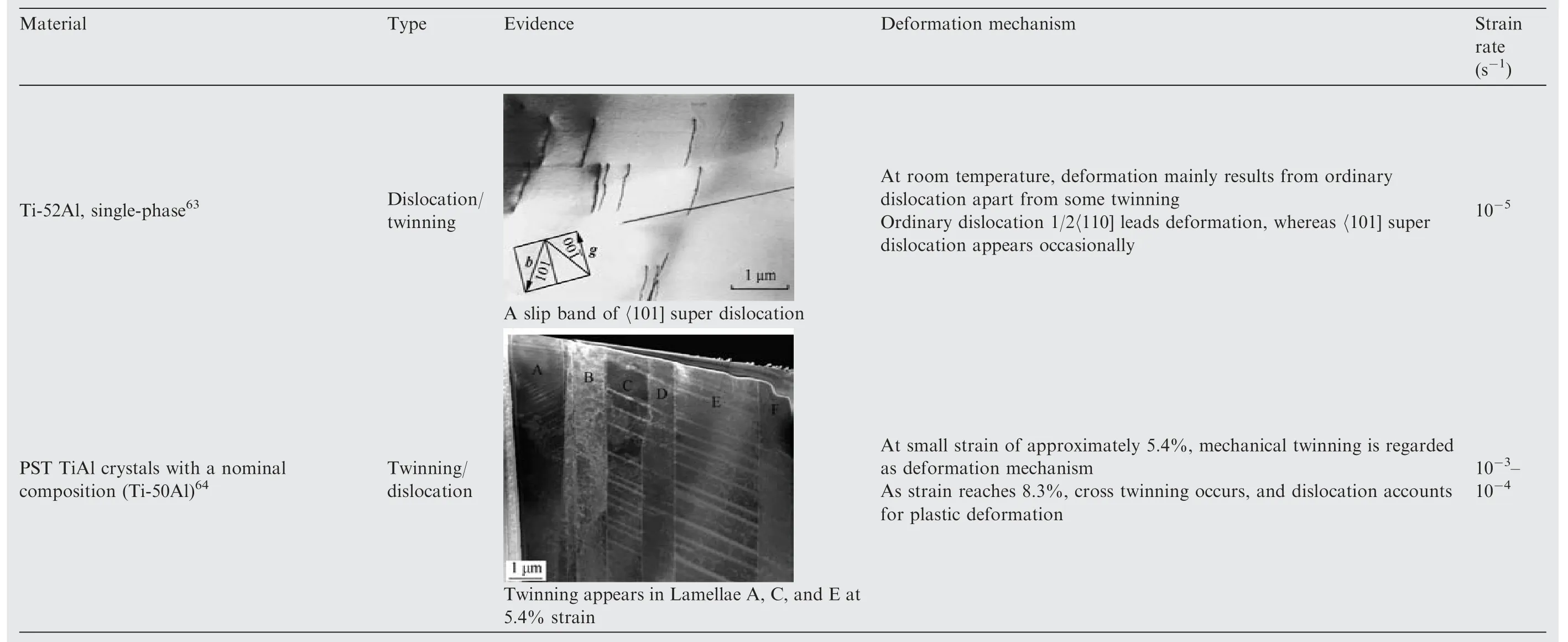
Table 2 (continued)

Fig.7 Relational network of some factors affecting performances of γ-TiAl.

Fig.8 Poor machinability of γ-TiAl.

Fig.9 Main research content summarizing and trends of cutting mechanism of γ-TiAl.
However, a study by Uhlmann et al.73showed another result.They conducted a quasi-static cutting (vc= 0.01 m/min) test on TNB to investigate the variation law of the specific cutting force (Kc) with temperature, where Kcrepresents the necessary energy of the material unit separation,which is an expression of the shear stress and various angles of the shear zone.The chip morphology and surface cracks suggested that increasing the temperature improved the ductility of the material.Nevertheless, a higher cutting force was observed with increasing temperature.The reason for this was believed to be a higher amount of plastic deformation.
Undoubtedly, lubrication strategies can improve worse cutting-zone environments.Klocke et al.74conducted a turning test on TNB under different lubrication methods.Compared to the cutting speed and depth, the sensitivity of the cutting force to the feed rate was low under MQL.Thus, the material removal rate can be increased by increasing the feed rate.In addition,the cutting force under CC was reduced by three time compared with that under dry cutting, as shown in Fig.10.74Subsequently, Klocke et al.18investigated the cutting force required for machining 45XD with high-pressure lubrication(30 MPa) and found that the passive force was approximately 17% lower than the cutting force under conventional cooling(0.6 MPa)and a 41%decrease in tool flank wear.The vapour bubble theory explains that increasing the pressure can enhance the mechanical pressure of the lubricant.As pressure acts on the boiling fluid near the cutting edge,a vapour bubble is formed such that the cutting zone is isolated.

Fig.10 Cutting force and tool wear of turning TNB under different lubrication conditions with vc = 100 m/min, ap = 0.4 mm.74
At present, a large number of experimental studies have been conducted to monitor the cutting force required for γ-TiAl, however, few have analyzed the mechanics in the cutting zone.Hussain et al.76proposed a cutting force model database of milling 4822 alloy.The cutting force model was based on the method of the oblique cutting model by discretizing the cutting edge unit (See Fig.11(a)76).The fundamental unit cutting force model is
where dFt, dFr, and dFaare the unit cutting force along tangential, radial and axial directions; Ktc, Krc, Kac, and Kte,Kre, Kaeare special cutting forces and the cutting edge coefficients in the three directions respectively,as well as uncut chip thickness h(φ) and unit cutting edge length in axial.The calculation methods of the cutting coefficients were referred to Ref.93, and then some fundamental parameters can be obtained by the orthogonal turning test.Some critical parameters can be expressed as follows.
The friction angle is
The friction coefficient is

where αris the tool rake angle;Ffcand Ftcare average feed and tangential cutting force;F is the resultant force;b is the cutting width; h and hcare uncut chip thickness and chip thickness,respectively.As shown in Figs.11(d)76and (e),76the cutting force of two milling 4822 alloy patterns was predicted, including plane milling and airfoil profile milling.A good agreement in measure and prediction was kept except for some unstable factors in processing, like vibration and noise.
Further studies should consider the key factors affecting the cutting force.Some previous works reported the improved cutting model considering more factors,like tool deflection,94tool wear,95and a new uncut chip thickness evaluation method.96Cheng et al.9developed a cutting force model that considered the tool flank wear while turning γ-TiAl(Ti-47.5Al-2.5-1.0Cr).Referring to Hou et al.,97the cutting force model was considered in two parts,the cutting forces Frakeand Fflankon the rake face and the flank face.To simplify the model, a linear relationship between Frakeand the cross-sectional area of the unformed chip was assumed.Consequently, the three component forces on the rake face along x, y, z of the orthogonal plane can be expressed as
where Kf, Kp, and Kcare the special cutting forces coefficients in the three directions respectively; f is feed rate; apis cutting depth.
On the flank face,only friction force Ffhand press force FNhof the normal plane were considered, which were only related to tool wear.In a further step, both were considered in the orthogonal plane to facilitate calculation.Hence, the three component element forces of on flank face along x, y, z are expressed as
where β is the angle between the orthogonal plane and the normal plane; VB is the wear bandwidth; dz is the distance to the cutting edge; τ(z) and σ(z) are shear stress and normal stress,respectively; l is unit flank length.The final predicted cutting force was the sum of the components in the orthogonal plane.The study reported that the error between predicted and tested values remained below 17%.
A noteworthy point is how BDT affects material ductility.This is closely related to the stress that meets the material yield.Based on this, a higher-accuracy cutting force model can be accessed.Therefore,temperature information of cutting γ-TiAl should be considered seriously.
3.2.2.Cutting temperature
Low thermal conductivity of γ-TiAl induces higher cutting temperatures.Hood et al.79measured the temperature of ball milling 45XD, indicating a positively correlated with cutting speed.In addition, Aspinwall et al.44examined the temperature of milling 45XD.43%–47% growth rate was obtained when vcvaried from 50 m/min to 135 m/min.Additionally,the average of all the test results showed that the infrared temperature measurement was approximately 28%lower than the constant temperature measurement.
There is a challenge to find a good way to overcome the series of adverse consequences caused by brittleness of γ-TiAl.Several researchers prefer to use HSM to increase the material temperatures,thereby softening the materials.The most focused point on this topic was BDT,which is produced by a temperature that induces a crystalline material to undergo a brittle to ductile transformation.Uhlmann and Herter78reported that the BDT temperature of γ-TiAl is approximately 650 °C.
Imayev et al.77believed that the thermal activation caused it by studying the BDT mechanism of Ti-50.7Al.The BDT can be divided into two stages.Improved ductility results from the grain boundary relaxation in the first stage.The grain boundaries absorb the lattice dislocation and promote the active dislocation density.In the second stage,the stress derived from piledup dislocations will relax inside the grain by recrystallization and dynamic recovery.Thus,the material macroscopically exhibits enhanced ductility.As shown in Fig.12,77increasing temperature released the Trapped Lattice Dislocations (TLD) in the grain boundaries from less than 10% to approximately 90%.Moreover, the BDT critical temperature Tcis related to the grain size, with Tc> 600, 750, 850 °C corresponding to the grain sizes d = 0.4, 14, 17 μm, respectively.
The increase in dislocations during thermal activation is mainly due to the dislocation unpinning mechanism, which is also related to the climbing of ordinary dislocations.98Lipsitt et al.27reported that superdislocations 〈011] decomposition would also promote the plastic transition.Whereas it occurs only at high temperatures.Thus, the mechanism that occurs during cutting is currently unclear.
Even if the tool wear with 0.3 mm was used to mill 45XD(vcreached 345 m/min), Aspinwall et al.44surveyed that the cutting temperature (the maximum value 413 °C) failed to exceed the critical condition of BDT.Uhlmann and Herter78carried out the turning γ-TiAl,indicating the cutting temperature above 700°C(as vc=300 m/min).The state of the chips and the surface cracks provided compelling evidence to verify the BDT phenomenon.And then,Uhlmann et al.73conducted a quasi-static cutting test of TNB using external heating equipment.Large-area cracks were distributed on the machined surface at RT.At 300 °C, the number and size of cracks were significantly reduced.Moreover, these defects disappeared at 800 °C.Although it is widely proven that high temperatures promote material ductility,more data are needed to characterize the quantitative relationship between the plasticity state of γ-TiAl and the cutting temperature.
3.3.Tool wear mechanism

Fig.12 Grain boundaries with and without trapped lattice dislocation.77
Many tests have shown that the poor machinability of γ-TiAl threatens tool life.Wang and Liu75presented the influences of cutting distance on the tool wear state in cutting Ti-47.5Al-2.5V-1Cr(See Fig.13,where all the tests were conducted with vc= 60 m/min, fz= 0.025 mm/tooth, ap= 0.1 mm, without lubrication strategies).The main wear mechanisms involved adhesive wear, flank wear, rake wear, and tipping.Severe tipping occurred when the cutting distance reached 30 m, and reached the wear standard of 0.3 mm.Moreover, the corresponding cutting force was over 450 N.Additionally, Mantle and Aspinwall70reported similar test results of high-speed milling 45XD.The cutting distance reached 80 m as VB= 0.3 mm, but the maximum cutting force did not exceed 300 N.Pérez71reported that the abrasive wear was severe while cutting 45XD because of the presence of boride particles.

Fig.13 Influence of different cutting distances on tool wear state.75

Fig.14 Tools wear state and corresponding energy dispersive spectrometer.85
Using Energy Dispersive Spectrometry (EDS), Yao et al.85investigated the tool wear mechanism of turning γ-TiAl in dry cutting.As shown in Fig.14,85workpiece elements such as Nb and Al were detected in Area 1# for the 408-SM inserts.The high temperature induced the oxidation reaction of Ti and Al elements with the surrounding medium, thereby increasing the content of oxygen elements.In Area 2#, elements were mainly derived from the tool-surface coating, which indicates that the area still maintained good tool performance.Cohesive wear was the primary type of wear.They believed that the contact area between the tool and the workpiece was small.Therefore, the pressure was immense.The cohesive phenomenon occurs once the contact distance is below the atomic scale.Cohesive wear results from cohesive grains or groups being sheared or stretched.The 412-MF4 inserts had a larger arc radius than the 408-SM inserts did.As shown in ② in Fig.14(a),85Area 1# shows cohesive wear, whereas Area 3#shows coating peeling off and Area 2# shows tipping.
Cutting speed is considered the most significant factor affecting tool wear.By studying the effect of cutting speeds on tool wear,Beranoagirre and Lo´pez de Lacalle81believed the optimal cutting was between 35 m/min and 45 m/min.Yao et al.85noted that cohesive wear dominated this speed range.While diffusion wear was the prime way,together with adhesion during the high-speed cutting of TNB.79
In terms of lubrication strategies,Priarone et al.82reported the effects of different lubrication methods on tool flank wear while milling 4822 alloy.As expected, dry cutting was the worst way.Wet cutting could prolong the tool life to some extent, and MQL was the most favorable lubrication method.Moreover, previous works have reported the bad side of wet lubrication by Priarone et al.99In wet cutting, the tool life may end in advance owing to severe thermal shocks.Klocke et al.18investigated the difference among the four lubrication ways (vc= 80 m/min).CC and high-pressure lubrication significantly suppressed the tool wear more than MQL.Wherein,the drop ratios were 61% (in CC), 41% (in high-pressure,30 MPa), and 7% (in MQL) respectively compared with conventional wet cutting.
With regard to the properties of the tool,the WC(tungsten carbide) tool with fine grain size possesses superior separation resistance, thereby improving the tool wear resistance.According to a report of Priarone et al.,84in wet cutting(vc=80 m/min),the tool life of turning TNM failed to exceed 1 min whether AlCrN coated WC,TiAlN coated WC,or 50%Cubic Boron Nitride (CBN) tool.In addition, abrasive wear occurred regularly in the uncoated WC tool until breakage.And the total process was approximately 2 min.CBN content is of utmost importance in tool life.Under the same cutting parameters,50%CBN only worked for 0.9 min,and the wear reached 0.242 mm, whereas 92% CBN was only 0.04 mm.Moreover,92%CBN caused a wear of 0.1 mm only after working for 6.9 min.The Polycrystalline Diamond(PCD)tools only reached this magnitude after operating for 15.9 min.Considering the high-temperature instability of PCD tools, it is necessary to adopt a cooling method for HSM.
In summary, the factors affecting the tool wear of cutting γ-TiAl consider the lubrication methods, cutting parameters,material properties, and tool performance.Different compositions and microstructures of γ-TiAl lead to different tool wear mechanisms.For instance, ceramic particles lead to abrasive wear during cutting 45XD, but cohesive wear dominates during cutting TNM.It is necessary to consider the four factors to make a suitable processing plan for tool life.Table 318,70–72,75,79,82,84summarizes the current studies related to tool wear while cutting γ-TiAl and provides the specific materials, tool types, cutting parameters, and lubrication methods as detailed as possible for reference.

Table 3 Summarizing influence of cutting conditions on tool wear.
3.4.Chip forming mechanism
The chip forming mechanism reveals, to some extent, what happens during the cutting process.Consequently, a deep understanding of chip formation contributes to the analysis of material deformation and the contact law between the tool and the material.
The chips of γ-TiAl are characterized by fragmentation with serrated sections.This is due to the high strength and low plasticity of γ-TiAl and the hardening tendency that occurs while cutting.Wang and Liu75surveyed the influence of different feed rates and cutting depths on the chip morphologies during cutting Ti-47.5Al-2.5V-1Cr, as shown in Fig.15(c).It can be observed that increasing the cutting parameters resulted in severe chip serration.The freedom surface of the chips had a lamellar structure, and scratches appeared on the back of the chips (See ①in Fig.15(c)).This is attributed to the extrusion and friction of the rake face against the chip at high temperatures and high pressures.The lamellar structure was more evident when the cutting depth reached 0.25 mm.Brittle cracks appeared between the lamellae because the cutting force exceeded the bonding strength between the lamellae.The fragmental chips occurred with the tool further feed.
The Adiabatic Shear Theory (AST) and Periodic Brittle Theory (PBT) are commonly used to explain the mechanism of saw-tooth chips.100,101Wherein AST is suitable for explaining plastic materials but PBT is for brittle materials, both of which are opposite and unified.Pérez71referred to the theories by Vyas and Shaw,101and Komanduri102describing the serrated chips formation of γ-TiAl in three steps (See Fig.15(b)71).In the first stage, shear plane O2 begins to form and defines the cross-section O12, which is squeezed by the feed tool in the next stage,and the free surface 12 bulges.The third stage covers three aspects: (A) As the plane O2 is formed, the critical shear stress results in the initiation and propagation of cracks; (B) Under the extrusion of the tool, the serrated chip unit slid upward along the shear plane to form a new serrated segment; (C) Next cycle is started, forming a new shear plane,O3.
In addition, the chip formation is also closely related to dynamic flow stress, which is highly sensitive to the competition between TSE and the Strain-Rate Hardening (SRH)effects.103Peng and Shareef87investigated the chip morphologies of turning γ-TiAl,indicating serrated chips with adiabatic shear bands at high-speeds and segmental at low speeds.This implies that the instantaneous flow stress affected the chip morphologies.Increasing the cutting speed has been proven to enhance SRH, resulting in increased flow stress and plastic deformation work.104With the low thermal conductivity, the cutting zone temperature increased rapidly.The critical cutting speed causes the TSE to dominate.It resulted in so severe thermoplastic instability that sawtooth chips with adiabatic shear bands occurred.

Fig.15 Forming mechanism and morphology of serrated chips.
Section 2.2 introduced how the microstructure types affect the material properties.Even with the same composition,materials with different microstructures evidently exhibit different behaviours during machining.However,multiple studies have reported the effect of cutting parameters on chip morphologies, while little is known about the microstructures.
More recently, Zhang et al.20surveyed the effects of the microstructures of Ti-43Al-9V, including NG and FL, on its machinability.The cutting force characteristics both in NG and FL were identified (vc= 50 m/min, ap= 5 μm), wherein FL was only 3.21 N.Interestingly,FL with the higher hardness resulted in a lower cutting force,which is closely related to the brittle fracture during chip formation.FL exhibited more brittleness than NG.105The serrated chip resulted from the brittle failure of the free surface.Thus,the rapid dissipation of cutting energy along the free surface of the chip is expected to reduce cutting forces.The corresponding Finite Element Method(FEM) model supported the conclusion that decreasing the fracture energy parameter weakens the serrated chip feature.Furthermore, Fig.1620shows the chip characteristics of the NG(representing γ grains)and FL(representing γ/α2lamellar colonies) microstructures.The serrated chip is common.The difference is that the former is relatively continuous.For the latter, numerous edge cracks extended inward into the chip at approximately 40 μm, indicating the brittleness of the γ/α2lamellar colonies.Additionally, severe grain deformation can be seen in the chips of NG (See Fig.16(c)20).In contrast, FL exhibited little deformation, other than chip curling.
3.5.Microscopic deforming behaviour of cutting γ-TiAl
Analyzing the Microscopic Deforming Behaviour (MDB) is conducive to understanding how deformation causes to other issues.Some vital information has been mentioned in Section 2.3, whereas the information presented in this section is based on quasi-static tensile/compression test results.Hence,more specific examples are stated, explaining tests performed at high strain rates.

Fig.16 Microstructures affect state of chips.20
Deeply understanding of the deformation behaviour requires an analysis of the material subsurface and chip state at the microscopic scale.Nevertheless, it is difficult to observe the dynamic deformation process directly with a large gradient and small size, which is limited by the current test devices and high costs.Therefore, Molecular Dynamics (MD) is the preferred method for simulating the microscopic cutting process,which pays significant attention to the influence of the interaction between atoms on defect structure, internal stress evolution, and removal mechanism of materials.106,107
An MD model developed by Li et al.90simulated the cutting of γ-TiAl Subsurface Deformation (SSD) on the nanoscale.Fig.17(a)90presents the dislocation distributions and microscopic defects at different cutting distances, such as vacancies, atomic clusters, and stacking faults, where①, ③, and ⑤are subsurface defects with cutting distances of 7.51 nm, 8.56 nm and 10.27 nm, respectively, ②, ④, and⑥ are dislocation types at cutting distances of 7.51 nm,8.86 nm and 18.00 nm, respectively.Wherein stacking faults were wrong forms of atoms stacked together (See ①, ②, and③in Fig.17(a)).The stacked structure continuously slipped along the Burgers vector with the tool feeding.Like stacking faults, dislocations consisted of stacking in several different directions, including Shockley partial dislocations and stairrod dislocations (See ②, ④, and ⑥in Fig.17(a)).Further,Jiang et al.91reported the dislocation evolution mechanism of cutting single-crystal γ-TiAl.During the cutting process, high temperature and pressure provided energy for the nucleation and migration of dislocations.These dislocations mainly appear along the [–1 –1 0] direction,covering Shockley partial dislocations, stair-rod dislocations and Frank dislocations.Wherein Shockley dislocation dominates the dislocation mechanism.Besides,growing the cutting speed could fall off the dislocation density but increasing cutting depth was the opposite.It is attributed to the increase of internal stress so that the workpiece obtains enough deformation energy.Therefore, dislocations have enough time to nucleate and interact with each other.Wang et al.89suggested that the higher cutting depth of γ-TiAl resulted in a more obvious evolution of defects such as subsurface dislocations and stacking faults.As a result,the dislocation density increased.

Fig.17 Investigating micro defects and dislocation evolution of cutting γ-TiAl.
Fig.17(b)88presents the dislocation nucleation process in the tensile subsurface state before/after cutting γ-TiAl.Subsurface nucleation of the processed material is not difficult,as the path extends from the subsurface to the internal workpiece.While uncut γ-TiAl with a strong boundary stress extends dislocations from the boundary to the internal workpiece.There were many Shockley partial dislocations during the initial tensile process,and other type of dislocations were formed through the interaction between the dislocations during the stretching process.Wang et al.89detailed how Shockley dislocations generated the Lomer-Cottrell dislocation.
Xie et al.92surveyed the subsurface defect evolution of scribed single-crystal γ-TiAl at different temperatures, as shown in Fig.18.Considerable dislocations were observed at RT rather than at high temperatures.This explained why amorphization caused by the high strain rate hindered the nucleation and propagation of dislocations to a certain extent(See Figs.18(a)92and(b)92).Concerning the dislocation length and density, the Shockley dislocations dominated the plastic deformation of γ-TiAl whatever low and high temperatures,which is in accordance with Jiang et al.91In terms of structure evolution, Fig.18(e)92presents that high temperature promoted the FCC →BCC transition and inhibited the formation of HCP but the FCC →amorphous crystal structure dominated.The difficulty of dislocation movement determines the metal strength,and its ability determines the metal ductility.108Consequently, high temperature resulted in crystallineamorphous interfaces, restricting dislocation movement.As a result, γ-TiAl still has desirable strength at high temperatures.
The abovementioned studies intend to simulate the subsurface defect evolution of single-crystal γ-TiAl.This can provide significant guidance to a certain extent.However, polycrystalline γ-TiAl is widely used in actual production, and the information on this material is still lacking.
MDB can be observed with advanced instruments like TEM.109,110Recently, Zhang et al.20observed a significant number of mechanical twins caused by Severe Plastic Deformation (SPD) in the PSZ of the NG microstructure(See ①in Fig.19(a),20where ①is TEM bright-field photograph of NG, ②, ③, and ④are enlarged views of Regions 1, 2, and 4, respectively).The overall slip of these parallel mechanical twins (〈112〉{111}) resulted from the shear force,as shown in ④in Fig.19(a).A high density of dislocations was found in γ-mechanical twinning (See ③in Fig.19(a)),implying that the early plastic deformation was dominated by dislocation slip, whereas twinning dominated the later stage.They believed the deformation was dependent on three dislocation types, as 1/2〈110], 1/2〈112] and 〈001].The first two types of dislocations were considered to be formed and moved at the initial deformation stage.And the SPD resulted in 〈001] decomposition at the later stage.In contrast, a brittle reaction was found in FL, indicating damage and bending of γ/α2lamellae (See Fig.19(b),20where ①is TEM bright-field photograph of FL, ②, ③, and ⑥are enlarged views of Regions 1, 2, and 3, respectively, ④and ⑤are Selected Area Diffraction Patterns (SADPs) of Areas A and B of ③).

Fig.18 Investigating influence of temperature on dislocation distribution.92

Fig.19 TEM photographs of partially formed γ-TiAl chips in different microstructures.20
Another worthy point is about the orientation angles of the FL microstructure of γ-TiAl.It is defined as the angle between the lamellar orientation and loading stress, which affects the fracture patterns and plastic deformation.20,111Typically,three fracture patterns are observed.When the angle is 90°,the shear effect results in a trans-lamellar fracture,whereas 0°causes decohesion.At an angle of 45°, γ/α2interface delamination is formed.More details can be found in the work of Chan and Kim.112

Fig.20 FEM of cutting γ-TiAl considering orientation angles.86
Zhou et al.86proposed an FEM model which considered the orientation angles.As shown in Fig.20,86the model introduced two crystal structures, Rectangular Lamellar (RL)and Regular Hexagonal (HL) lamellar structures.And four different lamellar structures represented the different orientation angles, including 0°, 45°, 90°, and full lamellar.Fig.20(b)86shows the edge fracture states of different crystal structures, where ①and ③are hexagonal lamella, ②and ④are rectangular lamella, indicating that negative shear angles were formed as the tool approached the edge of the workpiece.Regardless of RL or HL, cracks mainly occurred within the lamellae rather than the de-cohesion.Since HL with strong crack propagation resistance,the rougher fracture morphology was seen in HL (See ③in Fig.20(b)).Experimental results supported these discussions.
3.6.Discussion of machinability
Operators are dedicated to producing high-quality parts for use.However,all the detected indicators imply that machining γ-TiAl is not an easy task.Therefore, it is important to study their cutting mechanisms.According to the aforementioned content, Fig.21 summarizes the comprehensive research review on the cutting mechanism of γ-TiAl, where SEM respersents for Scanning Electron Microscope,EBSD respersents for Electron Back-Scattered Diffraction.The following discussion focuses on Fig.21.
The studying process of machining γ-TiAl can be concluded as follows:
(1) Preliminary preparation and determining test plan,where more attention should be paid to select parameters and processes.In addition, the microstructures and properties of the material must be clear in advance.
(2) After clearing errors (spindle runout, clamping error,etc.),it is necessary to monitor cutting force and temperature, collect chips, and record the cutting process.It may be limited to the laboratory level.
(3) Finally, the collected data and materials are processed and analyzed.In this step,potential relationships among the data must be correlated.The mechanical and physical changes while cutting γ-TiAl could be analyzed further.
Cutting speed is one of the most important factors affecting the variation of cutting force, which is caused by the TSE occurring at extremely high cutting temperatures.Conversely,some studies have suggested that the maximum cutting temperature could not be regulated to meet the BDT critical condition of γ-TiAl, 600–700 °C, but it is in the transition stage.It still helps to reduce the cutting force.Additionally, the thermo-mechanical coupling is an important method for understanding the cutting process and predicting other relevant factors.This is the basis for studying tool wear, material deformation, and metallographic alternations during machining.Currently, there is a lack of information on the development of a cutting force model that considers the BDT critical condition.
Dry cutting is worth promoting for green and sustainable development.However, some studies have claimed that the tool failed rapidly under dry cutting γ-TiAl, even for several seconds.The tool performance is affected by its composition.The smaller the particle size of the tool is, the better the wear resistance becomes.Moreover, the material properties affect the wear mechanism.As for 45XD and TNM, abrasive wear dominates in the former, whereas cohesive wear dominates in the latter.Although lubrication strategies can alleviate the tool wear rate,some studies have also suggested that thermal shock caused by sudden cooling may lead to tool cracking,the study reported by Priarone et al.99

Fig.21 Research network for machining mechanism of γ-TiAl.
At present, there are few reports on the effect of the microstructure on material deformation during machining.With TEM,SEM,EBSD,and other advanced detection methods, more valuable information can be pursued, in favor of analyzing the material deformation mechanism.The chip morphologies of γ-TiAl are generally serrated, which can be explained by AST and PBT theories.Recent studies have shown that reducing the amount of cutting suppresses serrated chips.The influence of flow stress on chip morphology mainly considers the competition mechanism between SRH and TSE.The serrated chips are likely to occur when breaking through the critical cutting speed.FEM can foresee these situations,but its accuracy is closely related to the material constitutive model.Accordingly, it is crucial that establish the highstrain-rate material constitutive model to simulate cutting γ-TiAl.On this basis, understanding the deformation mechanism at the microscale is an inherent requirement of the cutting mechanism.Although MD can determine the material defects evolution to some extent, experimental support is still required.The mutual justification, both in simulation and experimentation, should be paid more attention.Researchers have surveyed the relation between load and fracture pattern with respect to orientation angle.This can provide more potential to reduce surface cracks.However, the evolutionary mechanism during cutting is still unknown.
4.Surface integrity
Surface integrity refers to the overall description of the surface geometry and surface physical properties after machining a material,involving surface roughness and morphology,surface defects, residual stress, metallographic alternations, etc.(See Fig.22).19,113,114This is a crucial factor in affecting the part performance and reliability.Surface integrity is a concern owing to the intrinsic brittleness of γ-TiAl.
4.1.Surface roughness and surface morphology
Surface roughness is used to evaluate the surface finish of parts after processing, and it directly affects the assembly and accuracy of the parts.It relates to physical factors such as plastic deformation,elastic recovery,etc.,as well as geometric factors such as residual height resulting from tool path interference.

Fig.23 Surface roughness and topographies of turning γ-TiAl.85
As shown in Fig.23,85Yao et al.85employed turning tools with different chip breaker grooves,indicating that the smaller tool was suited for such brittle material γ-TiAl.Considering the effect of cutting parameters, the Raof the two tool types maintained a similar tendency.Wherein cutting speed exerted little effect on Rabecause of the brittleness of γ-TiAl caused fewer built-up edges and scale-fins.The effect of the cutting depth on Rawas considered to be the mechanical vibration caused by the increased cutting force and the severe extrusion of the chip and rake face caused by the large depth of cut.Besides, the growing feed resulted in a larger residual height,hr, thereby increasing Ra.Also, Wang and Liu75carried out a milling test of Ti-47.5Al-2.5V-1Cr (See Figs.24(a)–(c)).The influence of cutting parameters on Rawas investigated.Rafluctuated around 0.075 μm as the cutting speed increased from 40 m/min to 120 m/min.However, at 80 m/min, the defects resulted in an abnormal Ravalue.Additionally,increasing the cutting depth or feed rate could increase Ra.A reverse trend between cutting speed and Rawas reported by Priarone et al.80Rawas reduced about 23% as cutting speed varied from 35 m/min to 71 m/min (Ti-(32.0wt%–33.5wt%)Al).Regrettably, no further explanation was provided.
There is a common that increasing cutting depth and feed resulted in poorer surface finish.Wang et al.89deemed that the growing cutting depth was bound to induce larger deformation.Therefore, a lower cutting depth reduces the depth of the subsurface defect evolution layer to a large extent,thereby decreasing the surface roughness.
It is hard to compare the results of different studies directly owing to the different machining methods,material properties,tool types,etc.In the work of Settineri et al.,83the machinability of three γ-TiAl alloys was studied, in which all workpieces were dual-phase microstructures.According to Section 3.3,cutting 45XD exhibited the poor tool life,likely leaving hidden dangers for worse machined surfaces.However,4822 alloy presented a higher Ravalue than 45XD.Even so, some cracks or crack-like occurred in 45XD (See ②in Fig.24(d)83).It was considered as the presence of borides.18
There is a lack of explanation regarding the relationship between the tool wear and Raof γ-TiAl.Pérez71suggested that a worn tool did not directly cause an increase in Ra.A lower Raoccurred even at a high tool wear rate.Geometrically,trajectories interference between the corner radius and the feed induces small residual heights.Liang et al.115reported the worn tool produced a wiper effect to decrease the surface residual height caused by the feed, resulting in the lower surface roughness.Similar results could also be found in Ref.116.In contrast,Hood et al.79found a positive correlation between Raand tool wear, in HSM.

Fig.24 Surface roughness and topographies of turning γ-TiAl.
Zhang et al.20analyzed the different surface roughness of three microstructures of γ-TiAl.The surface roughness of cutting FL microstructure was higher than that of DP and NG.Fine grains promoted the anisotropy of the microstructure,which made the effective move distance of dislocations along the specific slip system small.As a result, the deformation of the machined surface was small.Moreover, the existing micro peaks and valleys of the surface with FL microstructure brought about the larger Rafluctuation.These peaks and valleys divide the surface into some areas.And the distance between adjacent regions was related to the grain size.This implies that grain boundaries are associated with surface peaks and valleys.For the smaller grain NG and DP, a shorter distance resulted in a flatter contoured surface.
4.2.Surface defects
Surface defects,such as tears,cavities,and cracks,are a potential threat to the fatigue life of parts.These defects can generate stress concentration that results in crack initiation and propagation.Especially for γ-TiAl used in aero-engines, fatigue resistance requirements are higher,and the surface quality standard is stricter.117However,suppressing surface defects in γ-TiAl is a significant challenge owing to its brittleness.
Furusawa et al.69investigated the crack state of the dualphase γ-TiAl (Ti-33.93wt%Al).Most were perpendicular to the cutting direction, with sizes of approximately 5–30 μm.The crack-growth process is described in three stages.Cracks initiated on the subsurface when the workpiece was subjected to extrusion and shearing from the tools.Subsequently, the moving tool expanded the crack span.Finally, the crack stopped expanding to a certain depth and formed a tear on the surface.In addition, cracks are considered as the mechanical strength of the lamellar structure, which is closely related to material microstructures.It formed easily as the cutting direction was perpendicular to these lamellae.Cracks across the lamella almost vertically can be seen in the work of Mantle and Aspinwall.118
To suppress the initiation and propagation of cracks, it is necessary to reduce the stress generated in the primary cutting zone.As shown in Fig.25(a),75Wang and Liu75suggested that the number of surface micro-pits seemingly agreed with the change in cutting force.Moreover,the interlayer bonding force is lower.As the cutting force over the bonding force, cracks were formed at the grain boundaries, and its propagation led to the pull-out of the lamellae, thereby forming pits.Bailey119believed the nucleation of cracks was closely associated with strain, strain rate, and temperature.Under the shear and extrusion effect from the tool, the primary cracks were born around the tool nose and grew along the maximum stress path.Crack or cavity defects would occur if cracks growth does not contact the surface layer.
In terms of material characteristics, Sharman et al.120conducted a turning test of 45XD (with NL microstructure) and found that the surface defects mainly covered lamellar deformation, cracked TiB2particles (borides were elongated), and cracks in the interior and surface (See Fig.25(b)).Elevating temperature can improve material plasticity, as discussed in Section 3.3.Increasing cutting temperature transforms the fracture mode of γ-TiAl, from transgranular-brittle type to intergranular brittle type to ductile type.77As reported by Uhlmann and Herter,78many microcracks were observed during low-speed turning γ-TiAl (vc= 60 m/min), whereas almost no cracks were observed during high-speed cutting(vc= 300 m/min).Further study, Uhlmann et al.73conducted quasi-static cutting after preheating γ-TiAl and indicated that the surface with no defect required over 800°C.Accordingly,a lower feed rate and cutting depth,and higher cutting speed are recommended to suppress the birth of defects.Fig.25(c)84presents the surface state both in the new and worn tools.The machined surface deteriorates significantly once the tool is no longer sharp.Multiple cracks and cavities occur when using a worn tool.
Grinding seemingly has fewer surface integrity problems than cutting.121,122Hood et al.123investigated the surface defects of grinding 45XD.Uncommon surface defects, such as side-flow ploughing and surface fracture, were observed when the D252 wheel (with a grit size of 252 μm) was used(See Figs.26(a)123and (b)123).Material flowed from the cutting path into ridges.Such the ploughing phenomenon was considered to be the wear of abrasive particles resulting in push rather than shear.Such fractures were not found after replacing the finer grit size wheel with 126 μm and 46 μm.Schubert and Nestler124suggested that microcracks and voids resulted from fracture and pull-out effects when the material surface was subjected to severe mechanical-thermal load.Hood et al.123also observed this phenomenon by evaluating the cross-sectional morphology of the subsurface (See Fig.27123).Fracture/pull-out could be found by using the D252 grinding wheel, which corresponds to the poor surface state (See Figs.26(a) and (b)).For D126 and D46 grinding wheels, no cracks or fractures were observed in the crosssections.This is consistent with the material surface morphologies.
4.3.Residual stress
The thermomechanical coupling effect induces the subsurface layer structure to cause changes to its shape,volume,and metallographic phase alternation relative to the matrix structure.And the residual stress is generated at the junction between the two layers.This affects the accuracy, fatigue strength,and corrosion resistance of parts.125,126Specifically, for the bearing and transmission parts, residual stress is a potential threat.The tensile or compressive residual stress is mainly related to the plastic deformation of the workpiece and the cutting heat.127The two stress types occur simultaneously,but the final stress state depends on their competition.128
Mantle and Aspinwall129monitored the residual stress by using the method of blind hole drilling.Some data were regarded as unreasonable, because the residual stress was greater than the ultimate strength of γ-TiAl.Hence,these data were only used for comparisons.The results indicated that tool wear and cutting speed significantly influence residual stress.Wherein the worn tool contributed to an increase in the area of the cutting edge intruding into the workpiece,thereby causing greater plastic deformation in favor of the compressive residual stress.While increasing cutting speed reduced compressive residual stress, it is related to cutting temperature.According to Yao et al.,85the increasing cutting amount led to the larger compressive residual stress and depth (See Fig.2885).It decreased rapidly with surface depth increasing and finally stabilized at –220 MPa (See Figs.28(a), (c), and(d)).In addition,Bentley et al.117found that compressive residual stress improves fatigue resistance and surface hardness.As shown in Fig.28(b),the variation trend of micro-hardness was the same as that of residual stress on the whole.
At present, published information on the residual stress of cutting γ-TiAl is few.Except for the little research on cutting γ-TiAl,the detection method of residual stress is also a critical reason.For instance,X-ray diffraction may be troublesome for detecting residual stress because the crystal structure of γ-TiAl results in overlapping reflections.130Furthermore, the blind drilling method is not recommended to detect residual stresses exceeding 50% of the yield stress.129Therefore, an accurate and effective residual-stress detection method is required.In addition, studies on the residual stress of γ-TiAl should focus on theoretical modeling of the highly nonlinear coupling of mechanical and thermal deformation and thermal deformations and the influence of process conditions,such as tool wear, on the magnitude and distribution of residual stress.Coupling theories and experiments may aid in exploring the residual stress evolution during the machining of γ-TiAl.In addition, the grain scale and variation law of the residual stress inside a grain should also be considered.

Fig.25 Typical surface defects of cutting γ-TiAl.

Fig.26 Surface morphologies of grinding 45XD with different diamond grit sizes.123
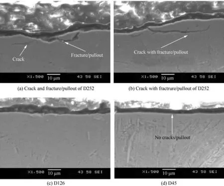
Fig.27 Cross-sections of subsurface grinding 45XD with different diamond grit sizes.123
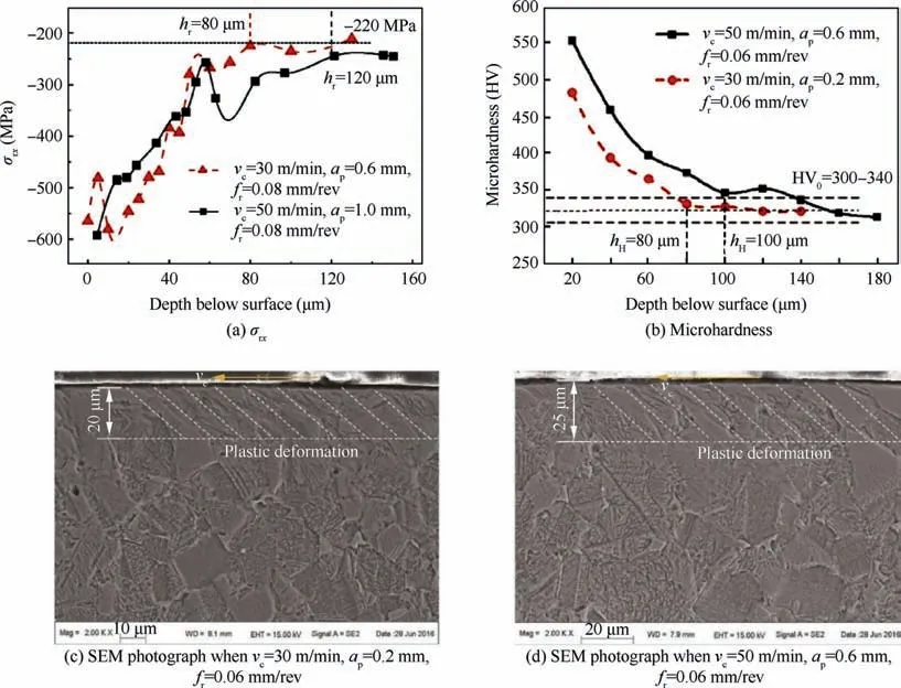
Fig.28 Residual stress, microhardness and plastic layer depth of turning γ-TiAl.85
4.4.Metallographical alternations
Previous works have shown that mechanical-thermal stress during cutting affects microstructural evolution.131It involves the grain size,grain rotation, the depth of the plastic deformation layer,etc.Guo et al.132believed that the microstructural evolution was closely dependent on the strain,strain rate,and temperature effects, as shown in Fig.29.Fatigue failure of parts is directly related to microstructural evolution and related physical and mechanical properties changes.133Therefore,it is important to understand the evolution of microstructures during the cutting process.This can provide more evidence to optimize the process to improve the surface integrity.
Currently, studying these subjects is prone to investigating chip and subsurface layer states by means of theoretical modelling, simulation prediction, and advanced detection equipment.Subsurface deformation is caused by the severe extrusion and friction occurring in the third deformation zone.This induces a series of crystal defects, such as dislocations,voids, and twinning, which is discussed in Section 3.5.Chip forming undergoes severe strain, strain rate, and temperature,and its goals are toward the dynamic recrystallization and phase transformation mechanisms.
Zhang et al.20published information on the metallographic state of the PSZ in ultra-precision milling γ-TiAl with NG and FL.The Inverse Pole Figure (IPF) and Phase Contrast Map(PCM) of the NG microstructure indicated that the plastic deformation of the cutting zone occurred in several grain regions,including γ and β grains(See Fig.30,20where different colors in Figs.30(a) and (d) represent different grain orientations).Conversely, there was no SPD, thus, the γ/α2colonies kept integrity.The Kernel Average Misorientation(KAM) results showed that NG, the PSZ had a larger strain concentration, whereas there was no such region in the FL.This indicates that the NG can withstand more deformation without cracking than the FL.

Fig.29 Interactive effects of deformation on microstructure.132

Fig.30 EBSD images of NG and FL microstructure of chips.20
Other factors, such as tool wear, that seriously affect the thermomechanical coupling effect significantly affect the microstructural evolution.However, related findings were almost undetectable in the case of γ-TiAl.All of these findings need to be explored in the future.
4.5.Discussion of surface integrity
Surface integrity is directly related to the machining quality and service life of the parts.However, the poor machinability of γ-TiAl results in its poor surface integrity.In pursuit of desirable surface integrity, a sacrificial material removal rate is necessary, but this greatly limits productivity.Some researchers have used HSM to reduce crack initiation and propagation, but extremely high tool-wear rates and excessive thermal stress may induce white layers or undesirable phase transformations.Therefore, developing a new cutting method with a low cutting force and temperature, suppresses tool wear, and reduces the adverse effects of mechanical–thermal effects on surface integrity is the goal for achieving highquality and efficient γ-TiAl components.
5.Conclusions and outlooks
γ-TiAl has been believed as potential materials for aero-engine LPT because of their excellent physical and mechanical properties.Previous reports have claimed that using γ-TiAl LPT to substitute superalloys can save fuel by nearly 20% and reduce nitrogen and oxygen emissions by 80%.In addition to improving the performance of aero-engines,they are also environment friendly.After more than 70 years of continuous iteration,γ-TiAl has been gradually applied in several fields over the past two decades.Nevertheless, its brittleness remains the biggest obstacle to commercialization.Although materials scientists have been working to overcome these obstacles, many problems are yet to be solved.These problems pose multiple challenges to machining.
From these available information, the machinability of γ-TiAl is rather unfriendly, manifested by high cutting force and temperature, severe tool wear, and poor surface integrity.Accordingly,this article provides a comprehensive overview of these topics.A common viewpoint is that HSM can effectively improve some aspects.However, a deep analysis of thermomechanical coupling has not been accessed yet.
According to the current research status, some potential research directions are proposed as follows.
(1) Preparation technologies and material performance breakthrough of γ-TiAl.
(A) It is technically difficult to control the phase transformations and microstructures of γ-TiAl.Even though some γ-TiAl types have been applied, some phase equilibria data are still lacking.Accordingly,γ-TiAl applied in aero-engine still required support from multiple data.At present, the competition and promotion mechanism of dislocations and twinnings have not yet reached a consensus.On this basis, high-speed computers can be used to carry out multiscale compounding and solidification simulations to analyze the influence of components on phase transformations, microstructural evolution,and material properties.Research on controlling the thermoplastic-deformation and heat-treatment on the microstructures can achieve better mechanical properties.This will make it possible to overcome their intrinsic brittleness while also acquiring better high temperature properties.
(B) Novel γ-TiAl forming method.The forming methods of γ-TiAl include precision casting, deformation, and powder metallurgy.New processes, such as additive manufacturing, and laser, have also received attention in recent years.However, ensuring the performance consistency of each position of the product,as well as the contradiction between deposition quality and manufacturing efficiency,still requires more data accumulation and exploration.
(C) Development of γ-TiAl-based composite materials.The goal is to overcome their defects while ensuring their own performances with the help of fiber and ceramic particle reinforcements.
(2)Developing the cross-field research on the cutting mechanism of γ-TiAl.
(A) At present, most of existing literature is prone to exploring the optimal cutting parameters of γ-TiAl,but lacks a deep consideration of the cutting mechanism.This often requires a combination of material science.For instance, HSM is commonly used to eliminate γ-TiAl brittleness.This is a result of the competition between TSE and SRH.And the BDT condition is considered as 600–850 °C.The actual cutting temperature, however, is hard to over the critical temperature.Although the material ductility is still improved, the deformation mechanism of the brittle-plastic transition stage is still unclear.Using MD can study the influence of cutting temperatures on dislocation activation at the microscopic scale,and explain the changing nature of material ductility gradient under the thermal influence.On this basis, a critical model for the brittleness-transition-plasticity of γ-TiAl can be developed to understand the critical ductility region cutting conditions of γ-TiAl.
(B) Attempts have been done to analyze the cutting force model of γ-TiAl.So far, there is no information considering such special characteristics BDT of γ-TiAl.In the future, developing a multi-factor thermal model to analyze the variation law and coupling characteristics between the force and temperature fields is needed.These works can provide a theoretical basis for residual stress and surface damage.
(C) The performance of γ-TiAl is very sensitive to the microstructures.There are still few reports on the relation between the microstructures and the machinability of γ-TiAl.Of these microstructures,FL and DP microstructures are reported to have commercial value.As fine grain size, DP shows better ductility and strength, but the high-temperature creep and fatigue resistance is not excellent.Although DP may exhibit good machinability, FL is more popular when serving in high-temperature sites.However, the ductility of FL is low due to the coarse grain size.Therefore, refining grain will become the objective in improving the machinability of FL.Additionally, the research on its machinability can be carried out from the aspects of grain size,lamellar content, lamellar spacing, lamellar direction, etc.In further research, exploring the effects of these factors on the machinability and fracture patterns of γ-TiAl is necessary.It contributes to an in-depth understanding of the material removal mechanism under high strain rate conditions.Moreover,it also has an important feedback on the material research and development, in favor of guiding the further optimization and modulation of the microstructures.
(3)In-depth study of surface defects and phase transformation evolution mechanism of cutting γ-TiAl.
(A) At present,there is little research on the deformation mechanism of cutting γ-TiAl.Some studies used MD to analyze the evolution of cuttinginduced subsurface defects and internal stress but lacked the support of experimental data.Thus, in the future, researchers should focus on mutual justification between the simulations and the experiments.
(B) Microcracks are prone to occur when cutting γ-TiAl.More attention should be paid to the influence of temperature, stress, friction, and temperature gradient in the cutting zone on surface defects under various composite actions and to deeply understand the initiation and extension mechanisms of cracks.This can provide a theoretical basis for developing a cutting technology that is highly effective and causes low-damage surfaces.Additionally, crack initiation has also been considered as the angle between lamellar orientations and the load, which needs further analysis.
(C) Based on the mechanical and thermal theories,the thermomechanical coupling effect of the PSZ can be understood in detail.Subsequently, by studying the critical condition of recrystallization during cutting, a controllable and predictive method of microstructure change while cutting γ-TiAl can be established.In addition, the influence of shear and extrusion in the cutting process on the subsurface deformation and the effective strengthening mechanism generated by the microscopic interaction with the deformed layer and the grain boundary between the matrix needs to be studied.This will instruct to develop the cutting technology with high surface integrity.
(4) Developing innovative technologies for γ-TiAl aerocomponents with the functional surface.Bionic functional surfaces can realize functions such as wear resistance, superhydrophobicity,and anti-icing.The surfaces are expected to prolong a part of service life and reduce noise and fuel consumption.At present, there are few reports on the use of functional surfaces in the aviation industry.In the future, it expects to study the influence of different surface microstructures of γ-TiAl on fatigue resistance and corrosion resistance and establish a multi-scale evaluation system.
Declaration of Competing Interest
The authors declare that they have no known competing financial interests or personal relationships that could have appeared to influence the work reported in this paper.
Acknowledgements
This study was co-supported by the Science Center for Gas Turbine Project, China (No.P2022-A-IV-001-002) and the National Natural Science Foundation of China (Nos.51875473 and 91960203).
杂志排行
CHINESE JOURNAL OF AERONAUTICS的其它文章
- Improving surface integrity when drilling CFRPs and Ti-6Al-4V using sustainable lubricated liquid carbon dioxide
- A hybrid chemical modification strategy for monocrystalline silicon micro-grinding:Experimental investigation and synergistic mechanism
- Analysis of grinding mechanics and improved grinding force model based on randomized grain geometric characteristics
- Experimental and modeling study of surface topography generation considering tool-workpiece vibration in high-precision turning
- Collaborative force and shape control for large composite fuselage panels assembly
- Ultrasonic constitutive model and its application in ultrasonic vibration-assisted milling Ti3Al intermetallics