Dielectric Patch Resonator and Antenna
2023-08-26JianxinChenXueyingWangShichangTangYongleWu
Jianxin Chen ,Xueying Wang ,Shichang Tang ,Yongle Wu
1 School of Information Science and Technology,and Research Center for Intelligent Information Technology,Nantong University,Nantong 226019,China
2 Nantong Research Institute for Advanced Communication Technologies,Chongchuan District,Nantong 226019,China
3 School of Electronic Engineering,Beijing University of Posts and Telecommunications,Beijing 100876,China
Abstract: This paper presents an overview of dielectric patch (DP) antennas developed in recent years.The employed DP resonator composed of a DP and a bottom substrate is analyzed comprehensively here,enabling the easy realization of a quasi-planar DP antenna.It combines the dual advantages of the conventional microstrip patch (MP) antenna and dielectric resonator (DR) antenna in terms of profile,gain,bandwidth,radiation efficiency,and design freedom.Furthermore,the DP antenna inherits the multi-mode characteristic of the DR antenna,thus it has a large number of high-order modes,including TMmn mode and TEmn mode.The high-order modes are widely applied,for example,by combining with the dominant TM10 mode to expand the bandwidth,or selecting multiple higher-order modes to implement a high-gain antenna.Additionally,the non-radiation high-order modes are also utilized to produce natural radiation null in filtering antenna design.In this paper,the design theories and techniques of DP antenna are introduced and investigated,including calculation and control methods of the resonant mode frequencies,analysis of the radiation mechanism,and applications of the multi-mode characteristic.This overview could provide guidance for the subsequent antenna design,thus effectively avoid time-consuming optimization.
Keywords: dielectric patch (DP) resonator;DP antenna;radiation mechanism;multi-mode characteristic
I.INTRODUCTION
With the continuous advancement of social informatization,the wireless communication system is developing rapidly in the direction of integration,miniaturization,and low loss.As the core component of wireless networks and devices,the performance requirements of the antenna are updated constantly,which is mainly reflected in the aspects of high radiation efficiency,wideband,high gain,and functional diversity.In the previous research,microstrip patch(MP)antenna has been widely used due to the superior characteristics,such as low profile,lightweight,high gain,and effective integration with RF active circuit[1–9].Initially,the characteristics of broadband,higher gain,or multiple functions of the MP antenna are achieved by adopting the stacked structure[4],specific feeding scheme [5],parasitic elements [6],or array [7],etc.However,these solutions inevitably increase the power consumption,volume,and design complexity of the antenna.Utilizing the high-order mode of the MP antenna is an effective way to solve the above problems.Researches show that the MP antennas operate at highorder modes have higher gains,whereas the frequencies of these resonant modes are far apart.Therefore,it is necessary to adjust single or multiple modes by introducing additional structures such as slots [8] or shorting pins[9]based on mode analysis.As a result,a wideband,dual-band,or multi-band MP antenna with high gain can be realized.Nevertheless,with the rapid commercialization of the fifth-generation(5G)mobile communication,the carrier frequency is gradually increased to meet the development requirements of high speed,low latency,and large capacity.In this case,the skin effect of metal becomes more significant,and the radiation efficiency of the MP antenna deteriorates sharply[10].As can be seen that the development of wireless communication systems is thriving,but the issue of how to ensure the radiation efficiency of microwave and millimeter-wave antennas and the arrays becomes more intractable.
To overcome the key technical bottleneck,the dielectric resonator (DR) stands out from the crowd and is extensively applied in antenna designs[11–14].DR is generally made of materials with almost zero conductor loss,resulting in high radiation efficiency,and has a significant application value in higher frequency,especially in the millimeter-wave band [15–17].Moreover,compared with the MP antenna,the three-dimensional DR antenna has multi-mode characteristic and can provide greater design freedom.Its high-order modes are widely utilized to achieve broadband [18–21],dual-band [22–24],or high gain [25–27] characteristic of the DR antenna to meet various application requirements.Nevertheless,the conventional DR antenna radiates through both the top and side walls of the DR,resulting in a relatively lower gain than that of the MP antenna.Additionally,most designs based on DR antennas have a high profile,which will limit their application in the development trend of miniaturization.
To solve the problematic issues,Dr.H.W.Lai,et al from the City University of Hong Kong compressed the conventional DR into a dielectric patch(DP),and fused it with a substrate to develop a low-profile DP antenna [28].Thanks to the anisotropic laminated structure,the antenna’s radiation mainly comes from the side walls of the DP resonator.The radiation mechanism is similar to that of the MP antenna.This means that the DP antenna has a higher gain than the conventional DR antenna while maintaining a low profile.Due to the existence of the substrate under the DP,the antenna can be effectively integrated with the RF active circuit,which avoids loading the tuning structure on the radiator to achieve reconfiguration[29].Besides,the DP antenna not only has high radiation efficiency comparable to the DR antenna,but the quasi-planar resonator still maintains the multi-mode characteristic.Its high-order modes,including TMmnmode and TEmnmode,are widely used to extend bandwidth[30–32]and enhance gain[33],or provide natural radiation null in the design of the filtering antenna[34].As early as 2014,the advantage of high radiation efficiency of the DP antenna in the millimeterwave is confirmed by A.-R.Sebak of King Saud University through an antenna array at 28 GHz [35].In 2020,the research team of Professor X.D.Chen,Xidian University,implemented a high-performance DP antenna array at 67 GHz by introducing the high-order mode into the operating band,and its radiation efficiency is as high as 89.2% [36].It can be found that the DP antenna integrates the advantages of conventional MP and DR antennas,and can provide important technical support for wireless communication systems.Furthermore,the DP antenna is suitable for the research of linear-polarization [28–31],[34–39],circular-polarization [32],and dual-polarization [33]antenna.It is comparable to MP and DR antennas in terms of form diversity and has tremendous application potential.
II.BASIC PROPERTIES OF DP RESONATOR
2.1 Evolution Process
In this paper,a comprehensive analysis of the DP resonator and antenna is carried out.Taking the construction of the analysis model as a breakthrough point,the frequency calculation methods of TMmnand TEmnmodes are investigated,respectively.On this basis,the influences of the physical parameters of the DP resonator on these two types of modes are explored.Furthermore,the radiation characteristics of DP antenna are revealed,including the radiation mechanism,gain control,and high radiation efficiency.Finally,the applications and implementation techniques of multimode characteristic in DP antenna design are summarized.
Essentially,the DP antenna is evolved from the conventional DR antenna,and the specific process is shown in Figure 1.Figure 1(a)exhibits the configuration of the conventional DR.A homogeneous DR is directly placed on the ground plane.In order to facilitate the implementation of schemes such as direct feeding,a substrate with a low dielectric constant is embedded between the DR and the ground plane for printing the circuit,as shown in Figure 1(b).The ground plane in Figure 1(a)or the substrate with a ground plane in Figure 1(b)only serves as a support.In both cases,the Efield of the resonant modes is mainly concentrated in the high-profile DR,and the basic properties are maintained.To obtain improvements in both profile and performance,the conventional DR is compressed into the DP(the heightHof the DR is much higher than the thicknesshdof the DP),and fused with the substrate to form a DP resonator(hdis approximately equal to the thicknesshsof the substrate),as shown in Figure 1(c).It is worth noting that when the profile of the DP is reduced to a quasi-planar level and fused with the substrate,its internal mechanism is transformed.The resonant mode analysis,design theories and techniques based on the conventional DR need to be adjusted accordingly.

Figure 1.The evolution process.(a)DR is directly placed on the ground.(b)Substrate is embedded between the DR and the ground.(c)DP resonator.
2.2 Theoretical Analysis
The theoretical analysis model of the DP resonator is shown in Figure 2.The dielectric constant of the DP and substrate areεrdandεrs,respectively.The volume of the DP iswd×ld×hd,and the thickness of the substrate ishs.Four side planes of the analysis model parallel to thez-axis direction are regarded as magnetic walls.The bottom ground plane is treated as an electric wall,which is used to half-cut the resonator.Here,the propagation direction of the electromagnetic field is along thez-axis.The resonant modes existing in the DP resonator can be roughly divided into two categories,namely TMmnmode and TEmnmode.The mode dominated byE-field (H-field) components in the propagation direction is the TMmn(TEmn) mode.The subscripts m and n represent the number of half cycle along thex-andy-axis,respectively.According to the electromagnetic field boundary conditions and Helmholtz equation,

Figure 2.Theoretical analysis model.(a)Analysis model of DP resonator.(b)The attenuation curve of the electromagnetic field along the z-axis.
the field component expression of TMmnmode and TEmnmode can be obtained.
For the TMmnmode,the field in the DP(|z|≤hd/2)is in the form of the standing wave,then the function along thez-axis direction can be described as a trigonometric function cos(kzz),
In the air (z≥hd/2),the field is attenuated along the +z-axis direction and gradually approaches zero,which can be described as an exponential functioneαz,
The field in the substrate (−hd/(2−hs) ≤z≤−hd/2)is also in the form of attenuation.But unlike the air region,there is a ground plane (electric wall)at the bottom of the substrate.Therefore,the function along the−z-axis direction should be regarded as the hyperbolic function cosh(α2z),
The remaining field components in the DP,air,and substrate are obtained by the following formulas,
wherekx,ky,andkzdenote the wavenumbers along thex-,y-,andz-axis,respectively.α1andα2are the wavenumbers of the dissipation mode along thez-axis in air and substrate,respectively.k0is the freespace wavenumber corresponding to the operating frequency.
Then,according to the continuity condition for the tangentialH-field andE-field at the interfaces of the DP,the following formula is obtained,
Finally,combining with the conservation of wavenumber in classical electromagnetism,
The frequency of the TMmnmode can be calculated by the following formula,
The frequency calculation method of TEmnmode can be analogous to that of TMmnmode.Due to the difference in field distribution,some expressions need to be adjusted appropriately.For TEmnmode,the standing wave field in DP(z≥hd/2),
The attenuation field in the substrate(−hd/(2−hs)≤z≤−hd/2),
The remaining field components in the DP,air,and substrate are described as,
Then according to the continuity condition and the wavenumber conservation relationship,the frequency of the TEmnmode can be calculated.Furthermore,based on the above expressions,theE-field distribution of TMmnand TEmnmodes can be drawn,which lays a good foundation for the design of highperformance or multi-functional antennas.
Figure 3 exhibits theE-filed distribution of the first mode of TMmnmode and TEmnmode,namely TM10mode and TE11mode.The calculated and simulated frequencies of these two modes under different physical parameters of the DP resonator are shown in Figure 4.When one parameter is changed,other parameters are fixed.It is found that the errors between the calculated and simulated results are all less than 5%,which better proves the rationality and accuracy of the above theoretical analysis.It can be seen from Figure 4(a)and (b) that asεrdor the aspect ratio (wd/ld) of the DP gradually increases,the frequencies of both modes shift downward.In Figure 4(c),whenεrsincreases,the frequency of the TM10mode move down,and that of the TE11mode is almost unaffected.As hs gradually increases,the frequency of the TE11mode always moves down.At this point,the frequency of TM10mode shows an upward trend when the DP is thick enough,and when it is compressed to a certain degree,the frequency moves downward,as shown in Figure 4(d).The variation ofεrdandhshas a significant influence on TE11mode,whilewd/ldandεrsmainly affect the TM10mode.It is worth noting that during these changes,as the DP becomes flat,the frequency of TM10mode is more persistently lower than that of TE11mode.In this case,the dominant mode of the DP resonator should be the TM10mode,which is close to that of the MP antenna.

Figure 3.The E-field distributions.(a) TM10 mode.(b)TE11 mode.
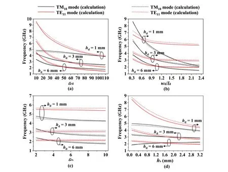
Figure 4.The calculated and simulated frequencies of TM10 and TE11 modes under different parameters of the DP resonator.(a)εrd and hd.(b)wd/ld and hd.(c)εrs and hd.(d)hs and hd.(Parameters: εrd=50,εrs=3.5,wd=30 mm,ld=30 mm,and hs=1.5 mm.)
III.RADIATION CHARACTERISTICS OF THE DP ANTENNA
3.1 Radiation Mechanism and Gain
Different from the conventional homogeneous DR,the DP resonator is formed by the fusion of a highpermittivity DP and a low-permittivity substrate.In the radiation characteristics analysis,the stacked DP resonator can be regarded as an anisotropic medium,and the equivalent dielectric constant is
whereεrx,εry,andεrzare the equivalent dielectric constants along thex-,y-andz-axes,respectively,which can be calculated by(15)and(16),
The reflection coefficients of the top wall (Rtop) and the side walls(Rside)can be obtained by the following equations,respectively.
The relationship between the reflection coefficients of each wall of the DP resonator can reflect the radiation mechanism.WhenRtop >Rside,the electromagnetic radiation of the DP antenna mainly comes from the side walls of the resonator[40,41],resulting in the radiation mechanism tending to that of the MP antenna,as shown in Figure 5.Therefore,the DP antenna has a higher gain compared to the conventional homogeneous DR antenna radiating through both the top and side walls.

Figure 5.Radiation mechanism of the antennas.(a) DR antenna.(b)MP antenna.(c)DP antenna.
Table 1 shows the influence of the ratio between the dielectric constant of the DP and the substrate(εrd/εrs) on the gain when the antenna is operating at the dominant TM10mode and the center frequencyf0=5 GHz.It can be seen that whenεrd/εrsrises,the calculatedRtop/Rsideincreases.The radiation mechanism of the DP antenna gradually approaches that of the MP antenna,and the gain can be enhanced from 5.4 dBi to 8.7 dBi or even higher.In this process,the half-power beamwidth (HPBW) of theE-plane reduces from 113◦to 61◦,and that of theH-plane changes from 82◦to 70◦.Besides,during the process of the DP being flattened,the influence of the radiation aperture on the gain cannot be ignored.Table 2 displays the effect of the aspect ratio(ld/hd)of the DP on the gain when the antenna operating at the dominant TM10mode and the center frequencyf0=5 GHz.Asld/hdrises,Rtop/Rsideincreases.In this process,the gain of the antenna is enhanced from 7 dBi to 7.8 dBi,and the HPBW of both theE-andH-plane is decreased slightly.
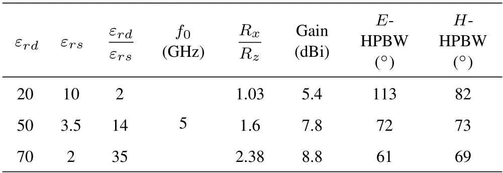
Table 1.Simulated gain comparison at TM10 mode of DP antennas with different dielectric constants.
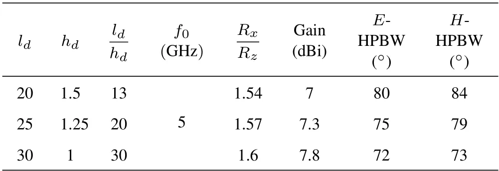
Table 2.Simulated gain comparison at TM10 mode of DP antennas with different aspect ratios.
It can be seen from the above analysis that the threedimensional layered structure of the DP antenna provides more design parameters,such asεrd,ld,wd,hd,εrs,andhs.The operating frequency and gain of the antenna can be controlled through a reasonable combination of parameters,and the desired performance can be obtained.This embodies the advantage of the flexible design of the DP antenna.
3.2 Radiation Efficiency
To verify the high radiation efficiency characteristic of the DP antenna,it is compared with the conventional MP antenna at 5 GHz and 10 GHz,respectively.At 5 GHz,the radiation efficiency of the DP antenna is 98%,while that of the MP antenna is 91%.When the resonance frequency is increased to 10 GHz,the radiation efficiency of the DP antenna stabilizes at 97%,while that of the MP antenna drops to 79%.As the carrier frequency gradually rises,the advantage of the high radiation efficiency of the DP antenna will become more significant.It can be found that the DP antenna processes great application potential in both microwave and millimeter-wave bands.
It can be found from Sections II and III that the DP antenna combines the dual advantages of conventional MP and DR antennas in terms of profile,gain,radiation efficiency,and design freedom.Moreover,it inherits the multi-mode characteristic of the DR antenna,and the high-order modes can be used to achieve performance improvements and multi-function.
IV.APPLICATION OF MULTI-MODE CHARACTERISTIC
To make full use of the multi-mode characteristic,the high-order modes are adopted to achieve the bandwidth expansion and gain enhancement of the DP antenna.The dominant TM10mode,high-order TE12mode and TE32mode involved in the existing designs are shown in Figure 6.In 2016,Prof.Y.M.Pan from South China University of Technology shifted the TE12mode down and merged with the TM10mode to achieve bandwidth extension by expanding the ratio between the plane size and height of the DP [30].Nevertheless,based on this traditional design concept,the plane size of the antenna is too large to meet the requirements of the element spacing in the array design.
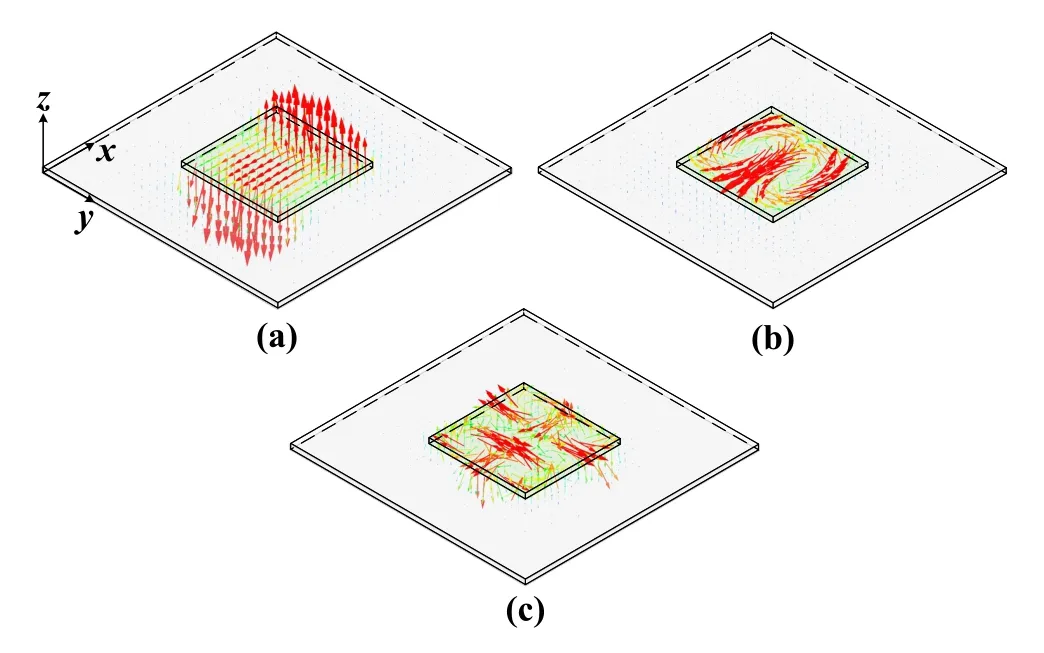
Figure 6.The E-field distributions.(a) Dominant TM10 mode.(b) High-order TE12 mode.(c) High-order TE32 mode.
To achieve a performance improvement while maintaining the original size of the antenna,two novel methods are proposed according to the E-field distributions of the resonant modes.It can be seen from Figure 6 that theE-field of the dominant TM10mode is mainly concentrated in the middle of the DP resonator,while that of the high-order TE12mode is stronger on both sides parallel to thex-axis direction.The first method is to etch a pair of silver-coated slots on both sides of the DP parallel to thex-axis direction [31],as shown in Figure 7.At this point,theE-field of the high-order TE12mode is disturbed by the silver-coated slots,which causes the frequency to shift down,while the dominant TM10mode is almost unaffected.It can be seen in Figure 7(b) that as the lengthlsor spacingdsof the sliver-coated slots increases,the resonant frequencies of the two modes gradually approach.In Figure 7(c),the impedance bandwidth of the DP antenna designed based on this method can be extended to more than 20%,and the in-band gain is stable.On the contrary,in the second method,four air holes are set in the position where theE-field of TM10mode is concentrated and that of TE12mode is weak [32],as shown in Figure 8.It can be seen from Figure 8(b)that when the diameter a of the air hole increases or the spacing d decreases,the resonant frequency of the TM10mode gradually moves up and approaches the TE12mode.Since the structure is completely symmetrical,the frequencies of the degenerate modes TM01and TE21,which are orthogonal to the two modes,also change accordingly.Therefore,by using a pair of cross-coupling slots of unequal length as the feeding structure,a circularly polarized antenna with an axial ratio bandwidth of about 10% can be obtained,as shown in Figure 8(c).

Figure 7.The wideband low-profile DP antenna[31].(a)Configuration.(b)The frequencies of the TM10 and TE12 modes against length ls and different spacing ds of the sliver-coated slots.(c) The simulated (solid line) and measured (dashed line)reflection coefficient|S11|and gain.

Figure 8.The low-profile circularly polarized DP antenna with bandwidth expansion [32].(a) Configuration.(b) The frequencies of the TM10 and TE12 modes against diameter a and different spacing d of the air holes.(c)The simulated(solid line)and measured(dashed line)reflection coefficient|S11|,gain,and axial ratio.
To further enhance the gain to implement a highgain DP antenna,two pairs of degenerate high-order modes,namely TE12and TE21,TE32and TE23modes,are selected to produce a dual-polarized operation[33].By introducing four grounded bars at an appropriate position in the DP resonator,as shown in Figure 9,the frequencies of the TE12and TE21modes are shift up,and the input impedance of the TE32and TE23modes is improved to be excitation.As can be seen in Figure 9(b)that the introduction of the grounded bars not only expands the bandwidth of the DP antenna but also further enhances the gain by more than 2 dB.Additionally,the remaining modes in DP resonators also have great application potential.For example,the nonexcitation and non-radiation high-order TM11mode can be used to provide natural radiation null in the design of the filtering antenna[34].
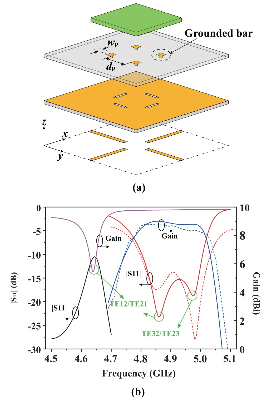
Figure 9.The differential-fed gain-enhanced dualpolarized DP antenna [33].(a) Configuration.(b) The simulated(solid line)and measured(dashed line)reflection coefficient |S11| and gain of the DP antenna with/without grounded bars.
V.LIMITATIONS OF THE DP ANTENNA
The limitation of the DP antenna is mainly reflected in the manufacturing and assembly.Based on the existing technique,the DP and the substrate cannot be integrally formed and need to be manufactured separately.During the assembly process,the air gap between the DP and substrate may affect the measured results.To minimize the introduction of airgap,we use the spring clips to press the DP on the specified position of the substrate and then fix them together with strong glue.But in certain applications,this assembly scheme may not be precise and robust enough.
VI.CONCLUSION
In this paper,a thorough analysis of the quasi-planar DP resonator has been conducted for designing a DP antenna.It is a good compromise between the conventional MP antenna and DR antenna in terms of profile,gain,bandwidth,radiation efficiency,and design freedom,and then has tremendous application potential in the microwave or millimeter-wave antenna field.This work provides reliable theoretical and technical guidance for the subsequent DP antenna design,thus effectively avoid cut-and-try simulation.
ACKNOWLEDGEMENT
This work was supported by the Natural Science Foundation of Jiangsu Province under Grant BK20201438,by the Natural Science Research Project of Jiangsu Provincial Institutions of Higher Education under Grant 20KJA510002,and by the Postgraduate Research and Practice Innovation Program of Jiangsu Province under Grant KYCX202825.
杂志排行
China Communications的其它文章
- A Survey on Channel Measurements and Models for Underground MIMO Communication Systems
- High-Performance Transmission Mechanism Design of Multi-Stream Carrier Aggregation for 5G Non-Standalone Network
- Predictive Tracking Implementation for Mobile Communication Using Programmable Metasurface
- Arbitrary Decode-Forward Relaying with Re-Encoded Bits Selection Strategy for Polar Codes
- Participants Recruitment for Coverage Maximization by Mobility Predicting in Mobile Crowd Sensing
- Distributed Edge Cooperation and Data Collection for Digital Twins of Wide-Areas