Joint target assignment and power allocation in the netted C-MIMO radar when tracking multi-targets in the presence of self-defense blanket jamming
2023-07-04ZhengjieLiJunweiXieHoweiZhngJihoXie
Zhengjie Li , Junwei Xie , Howei Zhng , Jiho Xie
a Airand Missile Defense College,AirForce Engineering University,Xi'an 710051, China
b Space Engineering UniversityofStrategic SupportForce,Beijing101416,China
Keywords:Netted radar system MIMO Target assignment Power allocation Multi-targets tracking Self-defense blanket jamming
ABSTRACT
1. Introduction
Owing to exploiting uncorrelated or orthogonal signals, the multiple input multiple output (MIMO) radar shows more significant advantages than conventional phased array radar [1,2], e.g.,waveform diversity[3—7],virtual aperture[8,9],and higher system degrees of freedom [10]. As the most promising MIMO radar, the collocated MIMO(C-MIMO)radar has gained research traction and gradually entered the practical realm [2—7]. However, in modern electronic warfare(EW),the working environment of radar systems can be interfered by enemy targets, thus reducing the combat capability of radars [10,11]. In this case, even if the C-MIMO radar has superior performance, its monostatic property can not ensure that the radar system has strong anti-jamming ability. On the whole, anti-jamming is a crucial advantage for the netted radar system(NRS)over the monostatic radar system[12,13].As a typical type of the NRS,due to the application of simultaneous multi-beam(SM) scheme [14], the netted C-MIMO radar is capable of tracking multi-targets at once in its region of interest (ROI). Thus, the analysis of multiple target tracking (MTT) in the netted C-MIMO radar under EW environment is of great significance. In practice,such systems require efficient strategies of resource management to provide better tracking performance.
Regarding the problem of resource management in the NRS,some significant works have been performed over the years[10,13—29].Generally,these works can be grouped into three parts,namely, setting up system structure [15,16], allocating beam parameters [10,13,17—20], and integration of the two parts[14,21—29]. In the first part, to solve the antenna subset selection problem, Ref. [15] proposes two operational policies based on the MIMO radar with distributed antennas for target localization.Ref. [16] derives the Cramer-Rao lower bound (CRLB) in terms of velocity estimation and then studies the problem of antenna placement to improve velocity estimation accuracy.As for the beam parameters allocation problem,Ref.[10]derives the posterior CRLB(PCRLB) for moving target state estimation and proposes a cooperative scheme for power allocation(PA)scheme in the MIMO radar with distributed antennas.Aims to improve system ability with low probability of intercept (LPI), Ref. [13] proposes a resource-aware scheme for tracking maneuvering target in the NRS. Ref. [17]further develops a standard PA scheme for MTT in clutter environment.In Ref. [18],a receive-beam assignment strategy for MTT is proposed based on the defocused transmit focused receive(DTFR) operation mode in distributed MIMO network. The collaborative power and bandwidth allocation problems in distributed radar networks are studied in Refs. [19,20] based on the LPI principle. To maximize the resource utilization of the netted C-MIMO radar [14], develops a joint scheme of beam and power allocation for MTT under the framework of centralized data fusion. On the basis of Refs. [14,21—23] carry out the studies for joint resource scheduling and parameter allocation in the distributed tracking system. To enhance the ability of maneuvering tracking in the netted C-MIMO radar system, Ref. [24] proposes a joint waveform control and resource allocation strategy. In order to improve the radar abilities of tracking and LPI in the NRS with phased arrays,according to the time division multiplexing (TDM) principle,Ref. [25] studies the joint scheduling scheme of target assignment and waveform parameter allocation. Aiming at improving system performance of localization and tracking,Refs.[26,27]develop the joint antenna selection and power allocation schemes in the distributed MIMO network. Based on the netted C-MIMO radar system, Ref. [28] proposes a joint radar scheduling and beampattern design strategy for tracking multi-targets. Ref. [29] considers sensors mounted on moving platforms, which has the characteristics of sensor location uncertainties, and further studies a joint power allocation and measurement selection strategy for MTT.
The above literatures appear to be fruitful in providing some guidance for addressing the resource management problem in the NRS.In fact,the previous works are mainly based on ideal detection scenarios or clutter scenarios, and the resource management problems in the NRS under EW environment are not studied.Moreover, the studies on MTT in C-MIMO radar network are limited,only shown in Refs.[14,21,24,28].Technically,a strong antijamming capability of the NRS can be attributed to its spatial diversity and abundant system resources. In particular, the data fusion task and the suitable tracking performance criterion are both crucial in ensuring the effectiveness of resource allocation in the NRS [30]. As a new type of the NRS, the C-MIMO radar network system can have more flexible task scheduling freedom and LPI ability than traditional NRS,thus it has a great potential in dealing with active jamming. To be specific, each node in the network transmits orthogonal beams to perform multiple tasks simultaneously. In this case, the netted C-MIMO radar system can flexibly schedule system nodes and optimally allocate transmit parameters to fight against enemy interference according to the real-time situation in EW.As far as we know,the resource allocation scheme in the netted C-MIMO radar under EW background has not been studied yet. Specifically, electronic counter measurement (ECM)under EW environment is mainly divided into blanket jamming and deception jamming, and the active blanket jamming is the most common interference method in modern battlefield.In fact,due to the jamming signals can affect the radar measurement accuracy and may lead to low signal to noise ratio(SNR),the relative position between the radar node with the target and the radar transmit power will inevitably affect the overall tracking accuracy.
To solve this problem,we propose a joint target assignment and power allocation (JTAPA) strategy for MTT application in the presence of self-defense blanket jamming using the netted C-MIMO radar. The main idea of this work is to optimize target assignment and power allocation to maximize the worst tracking accuracy of multiple targets carrying with self-defense jammers while meeting the real-time demand. To be specific, the resource management problems that we want to address are:(1)How many nodes should be selected as active nodes for tracking targets at every instant;(2)Which nodes are to be selected to track those targets; (3) How assigned targets can be allocated the limited power resource from active nodes.
In this paper, the following contributions are summarized as
(1) The JTAPA strategy is proposed for C-MIMO radar network when tracking multiple targets in the presence of selfdefense blanket jamming. At first, the network system model in the presence of self-defense blanket jamming is formulated. After that, we derive the predicted conditional CRLB (PC-CRLB) as an optimization criterion for JTAPA. As a result,the limited node resource and power resource can be optimally allocated by minimizing the worst case of PC-CRLB.
(2) We propose a two-step solution strategy to address the JTAPA problem efficiently. Mathematically, the JTAPA problem is considered as NP-hard due to its mixed-integer optimization form Ref. [27]. In this situation, our two-step solution strategy can provide a real-time suboptimal solution by solving the formulated optimization model separately. For the target assignment part, this algorithm uses a sequential relaxation-based method to improve solution efficiency. As for the power allocation part, the local searchbased gradient project (GP) algorithm is employed to ensure a certain solution accuracy.
(3) A closed-loop cognitive framework in the decentralized radar network is built for MTT.To ensure tracking accuracy,the decentralized particle filter track-before-detect(DPF-TBD)is used to obtain the global posterior distribution for tracked targets.The PC-CRLB are calculated based on the estimation results,which provides guidance in optimization process.In the last, the solving results are sent back to the system operate units for guiding MTT in the next cycle.
The remaining sections are listed below.In Section 2,we present the network system model. The decentralized MTT scheme is proposed in Section 3. We establish the optimization model and then solve it in Section 4.Section 5 presents the simulation results.This paper is concluded in Section 6.
2. System model
Consider that a C-MIMO radar network consisting ofN≥2 widely separated radars in the 2-D space.Assuming all the radars in this network operate in decentralized manner and thenth radar is located at (xn,yn), ∀n∈{1,˙˙˙,N}. There areQ≥3 far-field targets moving within the surveillance region. To simplify the analysis process, we make the following assumptions:
(1) All targets are space-separated in the ROI,and the number of targetsQis known as priori knowledge.
(2) All nodes are located far away from each other, so their mutual interference is not considered in this paper. Each node transmits defocused beams to illuminate its ROI and receives focused beams to extract target information,which is shown in Fig.1.
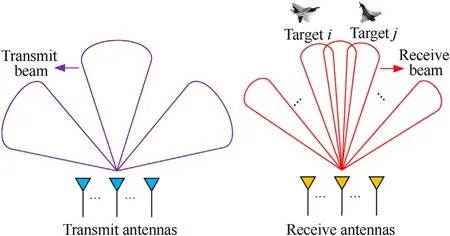
Fig.1. Illustration of the SM mode in the C-MIMO radar.
(3) The airborne self-defense jammer equips with the multibeam jamming system and transmits a series of narrow beams with uniform transmit power to the intercepted nodes.
(4) Each jammer operates in the same working mode and can intercept all the radars that are illuminating its carrier, i.e.,the interception probability is set as 1.
We introduce a binary variableun,k,qwhich denotes for target assignment result as follows:
With the assumptions above, an intuitive illustration of the described target assignment scheme for MTT in the netted C-MIMO radar system can be seen in Fig. 2.
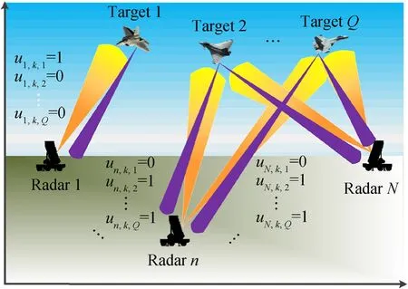
Fig. 2. Work-flow of target assignment in the established model.
2.1. Jamming signal model
To perform jamming signal coverage to the ground-based radars, the noise frequency modulation (FM) jamming signal is generated by the self-defense jammer.The blanket jamming signal is expressed as Ref. [31].
In this case, the baseband representation of the active blanket jamming signal received by thenth radar is given by
where τn,k,q=Rn,k,q/cdenotes the time delay. Herein,candRn,k,qare the speed of light and the radial distance, respectively.represents the jamming power and can be expressed as [32]
whereGJ,λJand γJrepresent the transmit antenna gain of jammer,the carrier wavelength of jamming signal and polarization mismatch loss, respectively.
2.2. Radar signal model under blanket jamming
Considering that the number of transmit subarrays isM,and all the subarray independently transmit orthogonal frequency-division multiplexing pulse signal, given bywherefcis the carrier frequency,Tpis the pulse width, rect(•)denotes the basic rectangular pulse envelope,φmis the initial phase of the subcarrier,and Δfis the frequency interval between adjacent subcarriers.
In addition,the effective bandwidth and effective time width ofcan be calculated by
wherehn,k,qdenotes the complex gain of target reflectivity,denotes the Doppler frequency,and τn,k,q=2Rn,k,q/crepresents the time delay.is the echo signal power [33].
wherePn,k,qis the transmit power,is the antenna gain,and λnis the carrier wavelength. Herein,gn,k,q(t) represents the complex Gaussian noise, which satisfies thatgn,k,q(t)~CN(0,
2.3. Motion model
It is assumed that target motion follows the constant velocity(CV) model [34], with
where I2denotes the second order identity matrix,Tsrepresents sample interval. The term of ⊗represents the Kronecker product operator. wk-1,q~N(0,Qk-1,q) with [35]
Herein,κfis the noise intensity associated with motion process.
2.4. Measurement model
The signal to noise and jamming ratios(SNJR)in radar receivers may be low when jamming signals are present. In this case, to obtain more target information, the coherent pulse accumulation(CPA) technique [36] and the maximum likelihood (ML) [18] estimate method are adopted during the whole processes.
Therefore, with the combination of the target assignment resultsun,k,q, the nonlinear measurement model is denoted by
where Zn,k,qdenotes the corresponding measurement sets ofqth target from thenth node and is given by
whereMn,k,qrepresents the number of measurements.is the single measurement information generated by real target or false alarm, given by
wherehn(•)=denotes the nonlinear transform function for distance and azimuth and can be expressed as
Herein,vn,k,q~denotes the measurement noisevector with the covariance
where ρndenotes the antenna aperture. SNJRn,k,qrepresents the SNJR in thenth radar for theqth target,which is computed by[32]
wherePg,n,kis the intensity of internal noise in receive end.Combining with Eqs.(10),(19)and(20),it can be noted that there is an inverse linear relationship between all the elements in Eq. (19)withPn,k,q. In this case, we can rewrite the measurement covariance matrix asTherefore, by increasing the transmit power to a target,the measurement error variance can be reduced to achieve higher tracking accuracy. Moreover, in the validation gate volume Wn,k,q, the false alarms are assumed to be independent and uniformly distributed, with the probability density functionp(wn,k,q) = 1/Wn,k,q.
3. Decentralized multiple target tracking
In this section, we develop the MTT algorithm in a distributed network as demonstrated in Fig. 3. Herein, each node provides its local estimate, and other nodes share their estimates. In this case,each node plays three roles, i.e., calculate local estimate, transmit local estimate information to other nodes, and obtain fusion estimate.
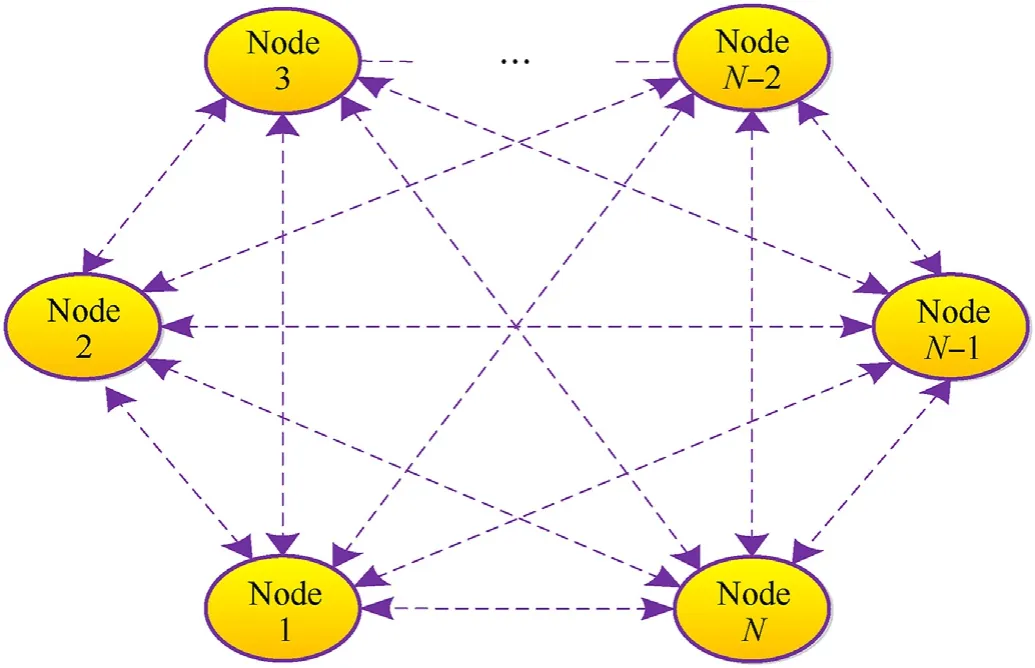
Fig. 3. The distributed dynamic network topology with M nodes.
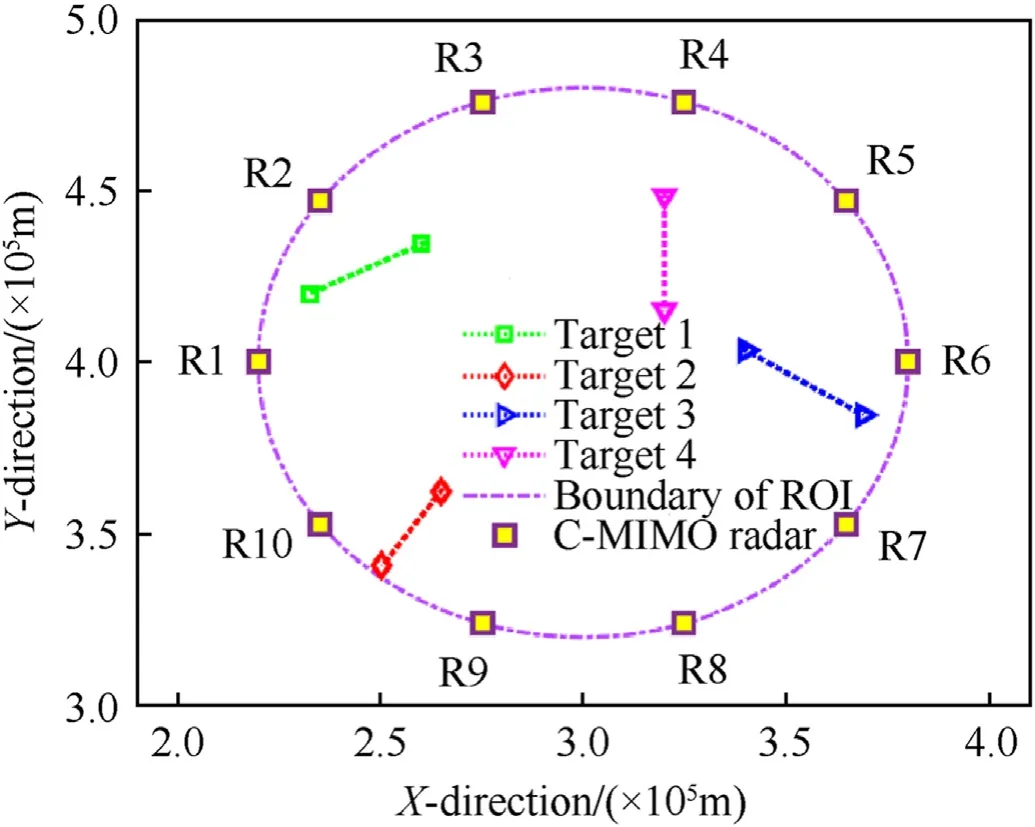
Fig. 4. The C-MIMO radar network configuration.
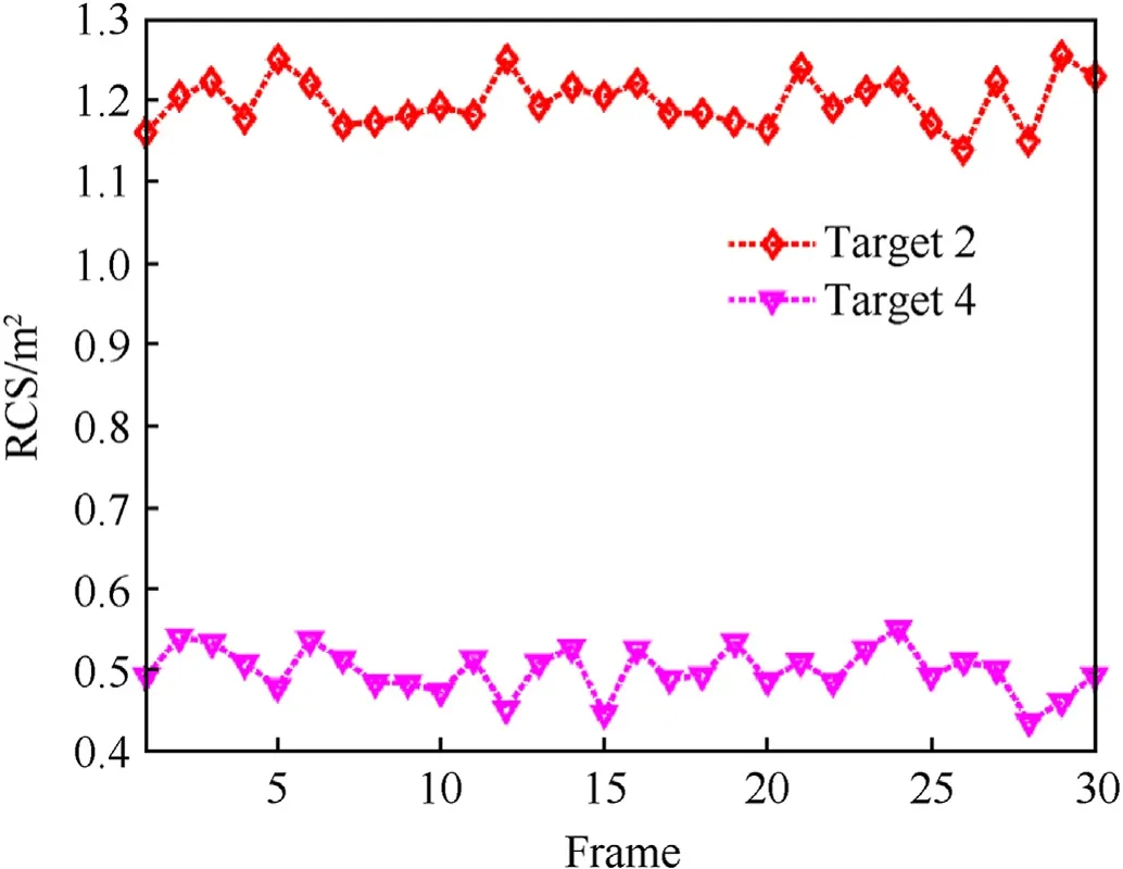
Fig. 5. The second target reflectivity model.
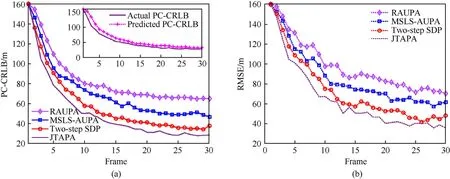
Fig. 6. Tracking performance under scenario 1: (a) PC-CRLB; (b) RMSE.
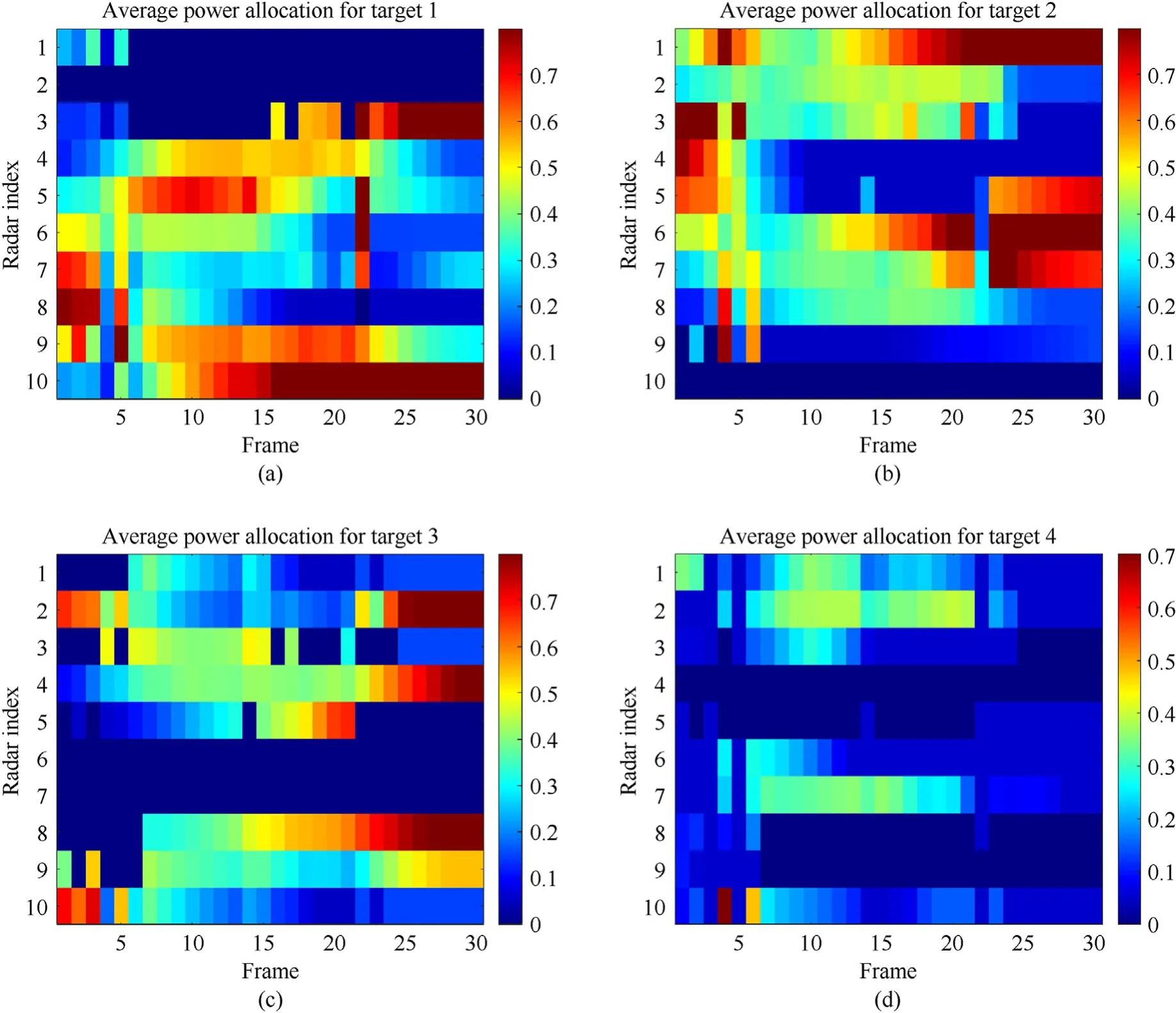
Fig. 7. The JTAPT results in scenario 1: (a) Target 1; (b) Target 2; (c) Target 3; (d) Target 4.
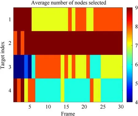
Fig. 8. The number of nodes selected for each target in scenario 1.
Since the particle filter(PF)performs well in nonlinear and non-Gaussian tracking systems [37], to tackle the problem of target parameter estimation under the condition of potentially low SNJR caused by jamming signals,an optimal fusion technique is used to generate the global posterior distribution based on the distributed dynamic network. After that, a weight update equation can be obtained by adopting the decentralized PF track-before-detect(DPF-TBD).
We define a target presence variablegn,k,q∈{0,1}, 0 and 1 denote no target present and target present with respect to nodenat sample intervalk. Moreover, consider thatgn,k,qfollows the Markov process, with the state transition matrix.
Hence, Eq. (16) is rewritten as
3.1. Optimal fusion
Assuming the global measurement vector can be expressed asBased on the Bayesian rule, the local likelihood functionis [38]
Moreover, the global posterior distributioncan be computed by
Combining with Eqs.(24)—(26),the final expression for optimal fusion can be obtained, given by
Therefore, for the posterior PF-based target tracking algorithm,the local node only needs to transmit the posterior density function and prediction function to data fusion center, so that a global posterior likelihood function (PLF) can be solved.
3.2. DPF-TBD algorithm
According to the Bayesian theory, the estimation of the target state and the target presence state can be separated.Then,the joint probability density function can be decomposed into
and
Moreover,the rest two elements in Eq.(29)can be expressed as
and
where
In addition,Cgis the normalization constant, given by
According to the above derivation,the summary of the proposed DPF-TBD algorithm is demonstrated in Algorithm 1.
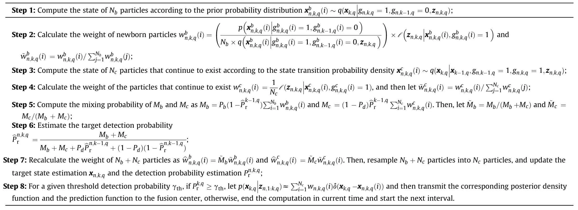
Algorithm 1DPF-TBD Procedure.
4. JTAPA strategy for multi-target tracking
4.1. Derivation of tracking performance criterion
Due to the high utilization of observation data in the derivation processes of the PC-CRLB[6,23,39],in order to satisfy the dynamic requirements in tracking process and obtain an accurate lower bound on the accuracy of the target state estimates,we set the PCCRLB as the optimization criterion [40].
4.2. Optimization formulation
From the mathematical perspective, the JTAPA is an optimization problem constrained by predetermined node resources and power budgets.Since the PC-CRLB can be predicted and is close to the state estimation error,we adopt the PC-CRLB as an optimization criterion. Further,when tracking multiple targets,we are trying to ensure that every target is tracked accurately.For this purpose,we use the worst case of the PC-CRLB as the objective function.
Take into account that location and speed are measured in different units, we normalize the PC-CRLB as
where tr(•)denotes the trace operator,Λ =І2⊗(1,Ts).The target assignment matrix Ukand the power allocation matrix Pkare defined as
In practice, the NRS rarely assign all radars to track a single target due to the limited data transmission rate and bandwidth limitation [14,46]. Also, for a given NRS, due to its degrees of freedom are fixed,the maximum quantity of orthogonal beams can be synthesized at the same time is fixed irrespective of its demand[4,6,7].Hence,we set at mostL(2 ≤L≤N)nodes can be assigned to track a single target at one tracking period. Moreover, considering each node generatesM(2 ≤M≤Q)beams simultaneously to track targets.Hence,to ensure each target can be tracked,for the binary variableun,k,q, the requirement should be satisfied.
The power budget of thenth node is given and defined asWhen the target assignment variableun,k,q=1,the corresponding powerPn,k,qshould be reasonably allocated to ensure adequate SNR for target tracking. Moreover, the transmit antennas in each node must maintain a certain level of activity.In this case,the constraints onPn,k,qmust satisfy thatAccording to the above analysis and assumptions, the optimization model can be formulated as follows:
4.3. Solution strategy
It can be seen that Eq. (45) shows a non-convex problem that combines the binary and the continuous variables [14,25].Although the best performance can be available by using the exhaustive search method, the solving process is more timeconsuming [23]. To solve Eq. (45) with lower complexity for computation, we develop a two-step solution strategy.
Step 1.Target assignment with uniformly allocated power. To simplify the calculation, we assume that each active node evenly distributes power resource to their assigned targets. This enables Eq. (45) can be rewritten as
Moreover, due to the existence of the binary variableun,k,q, Eq.(46) is considered as a NP-hard problem [15,47]. To tackle this problem,we introduce a relaxation technique[26],by replacing the binary constraintun,k,q∈{0,1} with the continuous constraintun,k,q∈[0,1]to obtain the relaxation form of the target assignment problem [48]. Thus, Eq. (46) can be obtained
where uk,qdenotes theqth column of the matrix Uk, and the functionis expressed as
It should be noted that the functionis monotonic decreasing with uk,q, which proof is shown in Appendix A. In this case,to solve Eq.(47)with lower computation complexity,we first relax its constraint as
Then, the optimal solution to Eq. (49) can be obtained by[49]
forq= 1,2,˙˙˙,Q, which yields to the inverse function
At this point,the optimal solution vectors(forq=1,2,…Q)of the relaxed problem Eq.(49)has been obtained.In addition,the optimal target assignment resultsfor Eq.(47)can be obtained by utilizing these lemmas:
Lemma 1.
Lemma 2.If≤min funqand thus the solutionis optimal(∀q∈{1,2,…,Q}).
Lemma 3.If>funq(argminwhere ∀q∈{1,2,…,Q},then,the qth row inThe proofs of the three lemmas are given in Appendix B.
Based on the three lemmas, the optimal solutioncan be calculated by repeatedly solving Eq.(49)and directly settingargminThe details of the whole proposed solving process are shown in Algorithm 2.
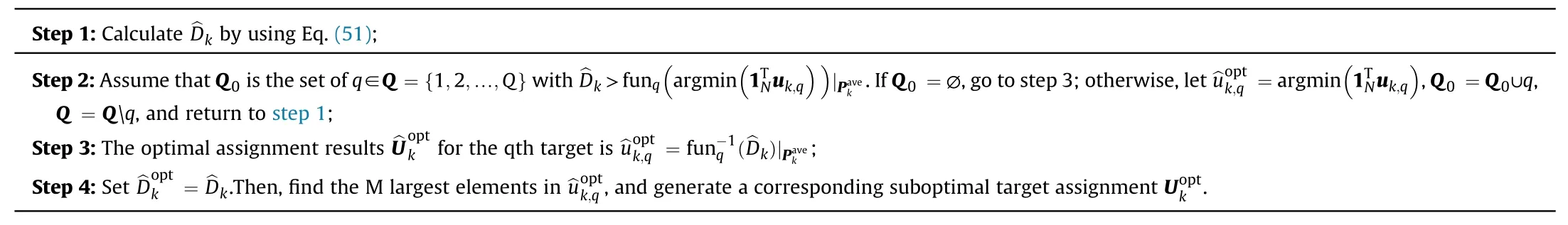
Algorithm 2The proposed target assignment strategy
Step 2.Power optimization allocation under the given target assignment results. After the target assignment solutionis obtained,we then allocate the limited power budget in each active node to its assigned targets.Since the power resources in the nodes are treated separately,the node index “n”is omitted for simplicity in the next analysis. In this case, the remaining optimization formulation is expressed as
The proposed target assignment algorithm has a complexity of O (N Q),while the exhaustive search method needs the complexity of O (2N(N Q)3).In addition,the power allocation solving algorithm has a complexity of O ((N Q)3), and the PC-CRLB calculation also has the complexity of O ((N Q)3) [50]. Hence, the operation of the proposed JTAPA strategy is with the complexity of O ((N Q)4).
5. Simulation results
5.1. Simulation settings
To demonstrate the correctness of the JTAPA scheme, some numerical results are presented in this section. Assuming the netted C-MIMO radar system is consisted withN=10 nodes with a diverse geography.For briefness,the operating mode of each node is assumed to be the same.In this case,the total power budget and the effective bandwidth in thenth node are given asPn,total=30 kW and βn= 1 MHz, respectively. Moreover, the carrier frequency is set as 2 GHz, and thus the carrier wavelength is λn=0˙15 m.The total power of each self-defense jammer is set as= 90 W. There areQ=4 moving targets in the ROI, and all targets follow with the CV model.The initial motion parameters of each target are given in Table 1,and the joint configuration of radars and moving targets is shown in Fig.4,respectively.A sequence of 30 frames with sample intervalTs=5 s is utilized during each Monte Carlo trail, while the number of Monte Carlo trialNsim= 100. The number of particles satisfiesNb=Nc=400,and the value range of transmit power is[Pn,min,Pn,max] =[0˙05Pn,total,0˙8Pn,total],forn=1,2,˙˙˙,N. The number of targets simultaneously tracked by each node is set asM= 3, and the maximum quantity of active nodes assigned to track each target isL= 9. To demonstrate the effectiveness of the proposed resource-aware strategy, the worst location root mean square error(RMSE) at thekth interval is given by
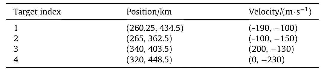
Table 1Target initial motion parameters.
Herein,we consider two different target reflectivity models.The first reflectivity model is constant radar cross section(RCS),that is,hn,k,q= 1m2(∀n,q,k). This scenario explores the effectiveness of the proposed strategy when the target reflectivity is factored out.In this case, the resource allocation results are only related to the system geometry and the jamming signals that timely associated with target assignment results. Moreover, in order to reveal the influence of the target RCS on the resource allocation results, the second target reflectivity model is established as time-varying,and the time-varying part is depicted in Fig.5,while the other RCSs stay the same as the first reflectivity model.
In addition, three benchmarks are utilized to show the effectiveness of the proposed JTAPA strategy.
(1) Random assignment with uniform power allocation(RAUPA). This method randomly assigns the nodes in the network to track targets, and the transmit power of each node is uniformly allocated;
(2) Multi-start local search (MSLS) [15] assignment with uniform power allocation(MSLS-AUPA).This algorithm uses the multi-start local search to select active nodes to track targets and uniformly allocate the system transmit power.
(3) Two-step SDP-based strategy [23]. In this algorithm, by ignoring the information reduction factor in Eq. (41), the target assignment and power allocation is formulated as a series of SDP problems and then solved by the standard optimization solver CVX [51].
5.2. Simulation scenario 1
In this scenario, we mainly consider the effects of the relative position of the netted C-MIMO radar system with respect with multiple targets on the resource allocation (RA) results. Thus, the first target reflectivity model is adopted.
Figs. 6(a) and 6(b) separately show the tracking performance among the four methods with respect to the worst case of PC-CRLB and the worst case of RMSE. Obviously, the RMSE approaches the PC-CRLB as the frame increases,which justifies the effectiveness of the established resource-aware feedback system. In addition, the proposed JTAPA strategy performs best among all the benchmarks.The subfigure in Fig.6(a)demonstrates that the predicted PC-CRLB is very close to the actual PC-CRLB,which verifies the correctness of the proposed JTAPA strategy.
The results of target assignment and power allocation for each target achieved by the proposed JTAPA strategy are shown in Fig.7.Different colors indicate the corresponding power allocated ratio,which is definedThe dark blue color denotes thatun,k,q= 0, while other areas denote thatun,k,q= 1.Fewer transmit resources are allocated to targets closer to radars,which is consistent with previous literatures [7,18,21]. This phenomenon occurs because the“MinMax”objective function tends to allocate more resources to the target when its tracking accuracy is the worst. Hence, in scenario 1, the targets which are closer to radars obtain less transmit resources, e.g., target 1 obtains the least resources from radar 1 and radar 2, and target 2 obtains the least resources from radar 10. In addition, although target 4 is far from radar 8 and radar 9, the transmit resources obtained are still quite limited. The reasons can be physically given as other assigned nodes have better angular spread condition than node 8 and node 9.
Fig.8 depicts the number of nodesselected for each target in scenario 1. The results show that a large number of nodes are allocated to target 2,while target 4 obtains the least node resource.This phenomenon can be intuitively explained as target 2 is closer to the edge of ROI and relatively far from the other radars,while target 4 is closer to the center of ROI and relatively even to all radars.
5.3. Simulation scenario 2
To further supports the influence of RCS on the RA results, the second target reflectivity model is adopted in this scenario.Hence,the RA results can be simultaneously affected by the target-node distance, angular spread,and target reflectivity.
Fig. 9 demonstrates the tracking performance in scenario 2.According to Fig.9,it can be noted that the proposed JTAPA strategy still performs better in the four RA strategies in scenario 2. Due to the weaker reflectivity in target 4,the worst tracking performance in scenario 2 has declined somewhat. In the second target reflectivity model, the tracking performance also fluctuates compared with the constant target reflectivity model in scenario 1.In Fig.9(a),it should be noted that the predicted PC-CRLB is still close to the actual PC-CRLB.

Fig. 9. Tracking performance under scenario 2: (a) PC-CRLB; (b) RMSE.
Fig.10 shows the JTAPA results.In contrast to scenario 1,target 4 receives more transmit resources due to reduced reflectivity. In addition, due to the higher reflectivity of target 2, the transmit resources obtained by target 2 are reduced compared to scenario 1.These results also imply the adaptive capability of JTAPA strategy.
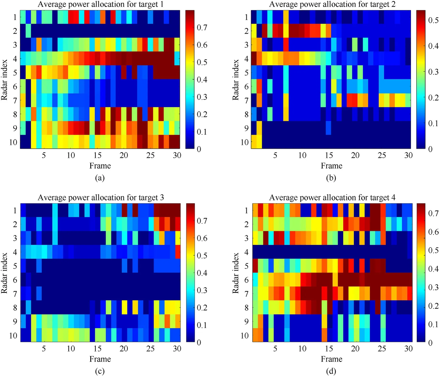
Fig.10. The JTAPT results in scenario 2: (a) Target 1; (b) Target 2; (c) Target 3; (d) Target 4.
The number of nodes selected for each target is given in Fig.11 for scenario 2.As the RCSs of target 4 weaken,the nodes allocated to target 1 increase subsequently.Meanwhile,the number of nodes allocated to target 2 decreases as its contribution to the worst tracking accuracy decreases. As can be seen, target 1 and target 4 are tracked most imprecise.

Fig.11. The number of nodes selected for each target in scenario 2.
5.4. Discussions and analysis
In this subsection,we further explore the timeliness of the JTAPA strategy.In our experiments,we used the MATLAB 2020b driven by the host with 3.7 GHz CPU and 16 GB RAM. The comparison of average CPU time by adopting the three optimal RA algorithms are shown in Fig.12.
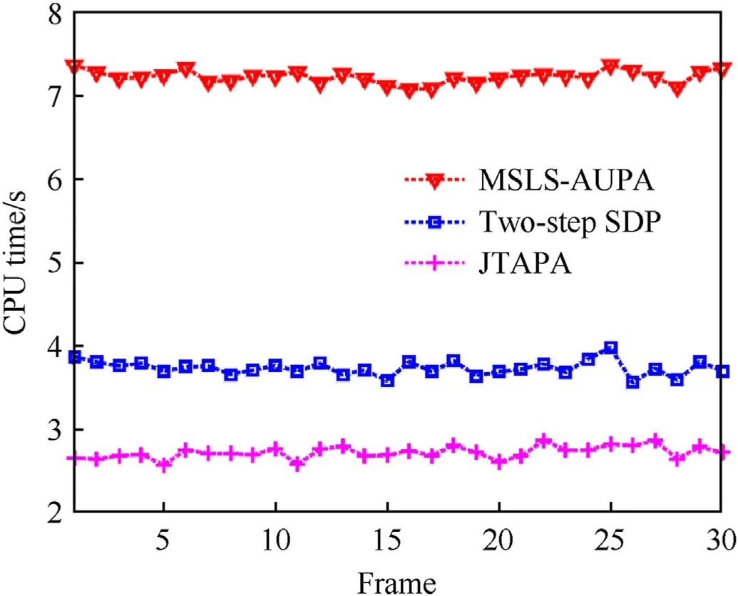
Fig.12. CPU time comparison.
Combining the results of two simulation scenarios, we can conclude the following:
(1) The proposed JTAPA strategy tends to assign nodes to track targets with further distance and weaker target reflectivity.Similarly, tracking errors are compensated for by allocating more transmit power to the worst-performing targets.
(2) The results of JTAPA can be affected by the reflectivity of moving targets and their relative position relationship with each node.
(3) In the above simulation scenarios,the predicted PC-CRLB and the actual PC-CRLB in the worst tracking case are very close,which proves the correctness and robustness of the proposed JTAPA strategy.
(4) The proposed JTAPA possesses a better performance in realtime, and thus is more suitable in practice.
6. Conclusions
In this paper, based on C-MIMO radar network, a joint target assignment and power allocation strategy was put forward when tracking multiple targets in the presence of self-defense blanket jamming. The DPF-TBD algorithm is adopted to estimate target state. The PC-CRLB is derived and utilized as the optimization criterion. Moreover, an effective two-step solver is proposed and adopted for solving the optimization model. Finally, simulation results verify the effectiveness and timeliness of the proposed method.
In the future work, more complex active blanket jamming modes will be considered, e.g., optimal assignment of jamming beam and optimal allocation of jamming power resource.
Declaration of competing interest
The authors declare that they have no known competing financial interests or personal relationships that could have appeared to influence the work reported in this paper.
Acknowledgements
The authors would like to acknowledge National Natural Science Foundation of China (Grant No. 62001506) to provide fund for conducting experiments.
Appendix A
Due to its linear constraints,Eq.(47)could be convex only if the objective function is convex.To facilitate later derivation,according to Eqs. (39) and (40), the PC-FIM can be rewritten as
where Wk,qdenotes the prior information,represents the measurement information.Obviously,Wk,qand Yn,k,qare symmetric positive definite.Hence, Eq. (48) is reformulated as
Appendix B
B1. Proof of Lemma 1
According to optimization theory [52], since ^Dkis the function value corresponding to the optimal solution of Eq. (49), Lemma 1 holds instantly.
B2. Proof of Lemma 2
杂志排行

Defence Technology的其它文章
- A review on lightweight materials for defence applications: Present and future developments
- Study on the prediction and inverse prediction of detonation properties based on deep learning
- Research of detonation products of RDX/Al from the perspective of composition
- Anti-sintering behavior and combustion process of aluminum nano particles coated with PTFE: A molecular dynamics study
- Microstructural image based convolutional neural networks for efficient prediction of full-field stress maps in short fiber polymer composites
- Modeling the blast load induced by a close-in explosion considering cylindrical charge parameters