Anti-sintering behavior and combustion process of aluminum nano particles coated with PTFE: A molecular dynamics study
2023-07-04JunpengLiuHaoruiZhangQiLongYan
Jun-peng Liu, Hao-rui Zhang, Qi-Long Yan
Science and Technology on Combustion, Internal Flow and Thermostructure Laboratory, Northwestern Polytechnical University, Xi'an 710071, China
Keywords:Aluminum nanoparticle Sintering Combustion Molecular dynamics simulation
ABSTRACT
1. Introduction
Metal particles are attractive and versatile additives in solid propellant (SP) for their high energy densities, combustion enthalpy and catalytic properties [1]. Among all available metal materials, aluminum stands out due to its rich content in earth,relatively easy ignition and nontoxic combustion products.Adding aluminum powders into SP can not only improve the combustion efficiency and burning rate [2—4], but also catalyze the thermal decomposition of other components, such as ammonium perchlorate (AP) [5,6]. Compared with its micron counterpart, aluminum nano particle (ANP) has larger specific surface area, lower ignition temperature and faster energy release rate,and for these reasons it has been widely used in SP formulations [1,7,8]. However, a large specific surface area endows ANP vulnerable to ambient environment in turn. Both water and oxygen molecules in the air are readily diffusing into the lattice structure of aluminum[9,10].Once the surface atoms oxidized as Al2O3,which is characterized as high boiling and melting points, the whole particle will be difficult to ignite. What’s worse, the highly reactive surface of ANP has poor compatibility with other components in SP and make ANPs more easily to agglomerate than micron particles.ANPs are easily to form agglomeration due to pre-melting process of surface,resulting in a serious negative effects for rocket, such as loss of two-phase flow,the introduction of unstable combustion and reduction of engine specific impulse [11,12]. Low content of active aluminum and agglomeration are obstacles for ANP application in SP.
An efficient way to solve above problems is coating ANP with other functional materials [6]. Since Pantoya and his co-workers firstly found fluorine containing polymers (FCP) could trigger the pre-ignition reactions between the coating layer and ANP[13—15],modifying ANP with FCP has been attracting growing interest.FCP can react with alumina before ANP’s ignition to produce AlF3with low melting and boiling points [13,16]. Among a wide variety of FCPs, polytetrafluoroethylene (PTFE) stands out due to its highest fluorine content, strong hydrophobicity and good compatibility with other components in SP [17—19].
PTFE acting as strong oxidizers can excite the surface exothermic reaction between alumina and fluorine, thus enhancing ignition and combustion of ANPs. Another praiseworthy point of PTFE coating layer is it could significantly reduce the agglomeration of ANPs which has been verified by experiments:Sippel et al.replaced bare ANPs with tailored Al/PTFE composite particles (70/30 wt%)and found PTFE coated ANPs could result in a reduction in average coarse fraction agglomerate size from either 75.8 or 125 μm [20];Yang et al. prepared energetic superlattice PTFE/Al materials revealing that self-propagating reaction could be adjusted by controlling the coating thickness and the superior performance of energetic superlattice materials produced finer combustion products [21]; In our previous research, we designed metastable intermixed composites (MICs) containing PTFE and polydopamine which is expected to control the reaction rate.Compared with bare ANPs, fluorine rich condensed products and vacant shell structure were identified by checking the SEM and EDS results[18].
However,due the complexity and instantaneity of reaction in SP,it is hard to investigate the sintering mechanism and combustion evolution process of ANP in propellant from nano meter space or femtosecond time scale. With the development of computing hardware, the emergence of reactive molecular dynamics (MD)simulation [22] has gradually become an useful tool to study the microscopic physical and chemical process of ANP. For example,Chakraborty and Zachariah applied reactive MD simulations to study the induced electric field generated at the core-shell interface during particle ignition which is a phenomenon could hardly be measured in experiments. Their results show the induced electricfield promotes agglomeration between particles which make the true particle size of ANP during combustion have to be reconsidered[23].Subsequently,their simulation findings were verified by experiments [24]. Sabzi et al. also paid attention to the effect of electric field establishment on particle sintering process [25]. Liu et al. studied the effect of organic coating layer on the sintering of ANPs and found the sintering rate is dominated by the surface potential energy of particles [26]. Sun and his co-workers systematically studied the sintering of nano particles and revealed the sintering mechanism of ANPs by MD methods [27]. Their work considered various possible factors that may affect nano particles sintering in energetic materials, including the heating rate [28],impact speed [29] and shock-wave impact [30]. More recently, EI koraychy et al.constructed Al—Ni nano particles deposited on Al(1 0 0) substrate models and found the sintering of hetero nanoparticles is significant at temperatures lower than melting point[31].
Base on quantum calculations, van Duin’s research group developed a reactive force field (ReaxFF) for Al—C—H—O system,making it possible to simulate the reactions between ANP and organic compounds [32]. After that, MD simulation on the adsorption and combustion of organic materials coated ANP has become a new verification and supplement for experiments[33,34]. Using MD method to study the ignition and combustion mechanism of ANP has also achieved great success: Liu et al. obtained the diffusion dominated combustion by analyzing the stress evolution at the core-shell interface[35];Shi and Liao summarized the size-derived reaction mechanism of ANP and successfully proposed the prediction model for ANP combustion mode[36—39].
Above work laid a solid foundation and provides MD simulation support for the current study. Although many experiments have been conducted,there are still a lack of simulation research on the sintering of double ANPs, especially for ANPs coated by functional coating materials. This paper is expected to reveal the mechanism of PTFE resisting the sintering of ANPs and help us understand the complex processes in SP more thoroughly. Comparative studies have been done between bare ANPs and PTFE coated ANPs to clarify the reason why PTFE coating layer can inhibit ANP sintering and improve its combustion performance. This work takes a first step on investigating the of ANP coated by PTFE molecules from a microscopic point of view, which could shed light on the study of agglomeration of coated multi-particles in the future.
2. Computational method
2.1. ReaxFF force field
ReaxFF force field allows chemical reactions happen in MD system,and its parameters are derived from the fitting of quantum calculation and experimental data. Different from the traditional molecular force field, ReaxFF does not pre-define the connectivity of atoms,but judges their interactions by calculating the bond order(BO)which is related to valence orbitals and inter-atomic distance.Eq.(1)shows how ReaxFF calculates BO value between atomiandjin MD simulations [40].
wherer0represents the equilibrium bond length and terms with subscriptpboare empirical parameters depending on elements.The equation is continuous and contains no discontinuities through transitions between σ,π and ππ bond characters. During MD simulations, according to initial coordinates of atoms, the force field will build bonded neighbor list for every atom to avoid spurious bond characters or any excessive close-range non-bonded interactions by introducing a shielding term. Such neighbor list will update every iteration step. More detail information about development of ReaxFF could be found in Senftle et al.’s review work[41]. The force field used in this paper comes from the work of Huang et al. The force field is developed for Al—C—H—O—F system specifically and the fitting process is also recorded in their article[42].
2.2. Model preparation
Two kinds of ANP models have been prepared before combustion simulations:core-shell bare ANP and PTFE coated ANP models.Because the effective aluminum weight content of commercially purchased ANPs usually reach to 70%, the Al:O ratio in the single ANP model has been calculated to meet this criterion. The initial bare ANP model has an aluminum core with a diameter of 56 Å(6194 atoms)and a 5 Å thick alumina shell(6074 atoms),both two parts are cut from bulk material.The gap between core and shell is set as 2 Å which is a region for fusing during the relaxation process.In the previous research on the melting points of ANPs, when the diameter of ANP greater than 50 Å,the melting point of particle will be close to that of bulk nano material.Therefore,a 56 Å core here is big enough to ignore the size effect during the thermodynamics process [43]. The initial ANP model was relaxed under canonical ensemble(NVT)at 300 K for 120 ps and the plot of potential energy versus time is shown in supporting information Fig.S1 in which the system potential energy fluctuates within 0.1% after 100 ps. Note that, a true equilibrium state will never be reached because of the diffusion of oxygen atoms into the aluminum core region[23].The relaxed ANP model as shown in Fig. 1 is built for subsequent simulations.
To obtain a fully PTFE coated particle,a bare ANP was placed at the center of 150 × 150 × 150 Å3simulation box with periodic boundary.800 PTFE molecules with carbon chain length of 8 were distributed randomly 12 Å above the ANP by using Packmol package [44]. Fig. 2(a) shows the initial configuration for PTFE coating simulation. To accelerate the coating process and ensure the PTFE molecules react with surface atoms as much as possible, it is necessary to ensure the adsorbent molecules have sufficient kinetic energy[45].Therefore,the whole ANP was set to 300 K whereas the PTFE solvent part was set to 500 K.The coating simulation lasts for 150 ps under NVT ensemble and 0.1 fs is chosen as the timestep.Subsequently, all atoms with distance greater than 45 Å from the center were deleted and a 300 K relaxation simulation was carried out to obtain the final coated ANP model for sintering and combustion simulations. Fig. 2(b) shows the cross-section view of the coated ANP. It can be seen from Fig. 2(b) that most carbon and fluorine atoms are adsorbed on particle surface in the form of single atom which indicates PTFE decomposes during the coating process and grafted structure also exists on the ANP surface.Note that,it is inevitable to find some atoms belonging to PTFE molecules fall off from particle surface due to the thermal vibration, all these atoms will be treated as unstable adsorbed atoms and deleted.
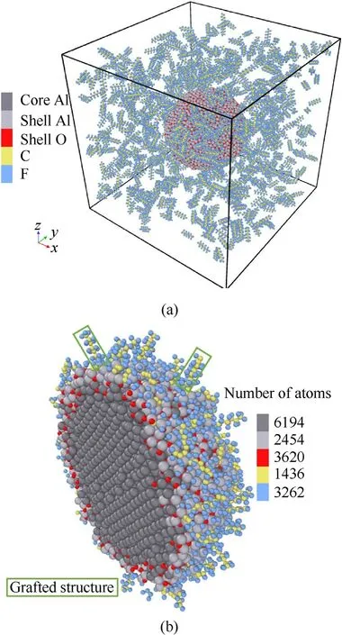
Fig. 2. (a) Initial configuration of PTFE coating bare ANP simulation; (b) Cross section view of ANP model fully coated by PTFE molecules.
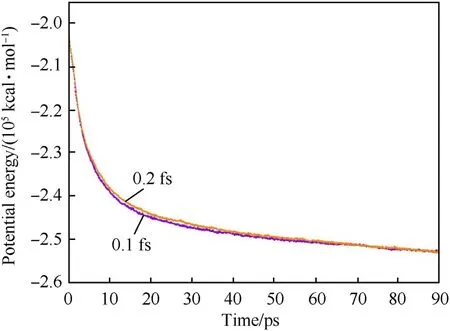
Fig.3. The time dependence curves of potential energy of coated ANP model by using different timesteps.
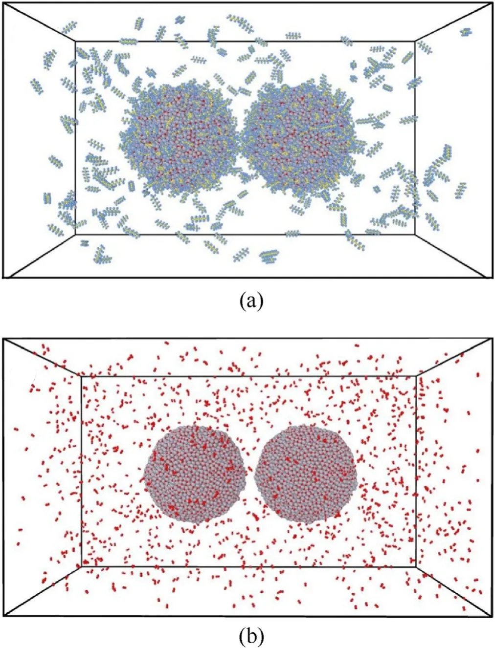
Fig. 4. Initial model of sintering-combustion simulations: (a) PTFE coated ANPs surrounded by 200 PTFE molecules;(b)Bare ANPs surrounded by 1200 oxygen molecules.
2.3. Simulation details
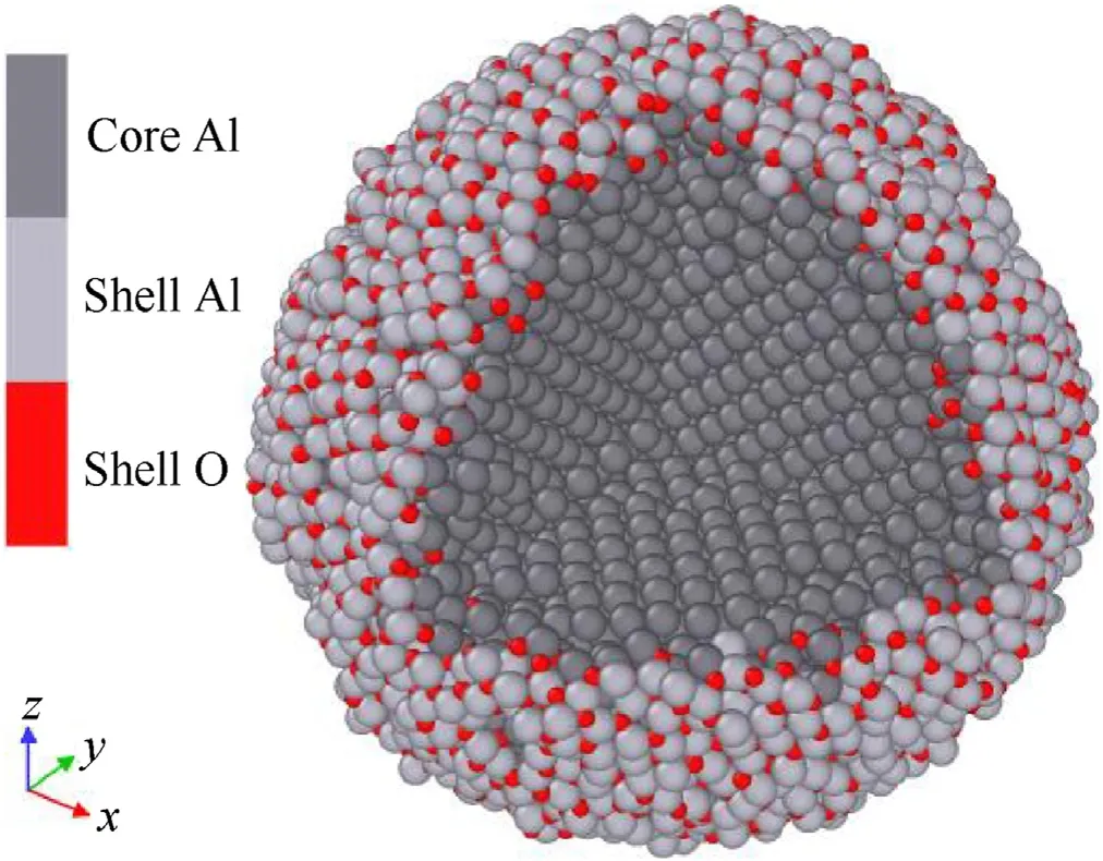
Fig.1. A bare ANP model with core-shell structure.
All simulations were carried out by using LAMMPS with USERREAXC package under NVT ensemble [46,47]. In our preliminary work,we adopted 0.2 fs and 0.1 fs to test the effect of timestep on the system energy. Relaxation simulations of PTFE coated ANP at 3000 K were performed 90 ps by using two different time steps.The potential energy varied with time is shown in Fig. 3 in which two potential energy plots almost overlap each other and both could converge to an approached potential energy. Considering the computational cost, 0.2 fs is selected as the time step for double-ANPs system.
For sintering-combustion study,the simulation box measured as 280 × 160 × 160 Å3with periodic boundary. Three kinds of scenarios containing double ANPs and related oxidants are built for comparative study.The first one is two coated ANPs surrounded by 200 PTFE molecules;The second one is two bare ANPs surrounded by 1200 oxygen molecules; The last one is two bare ANPs surrounded by 200 PTFE molecules as a reference case. The distance between two particles equals to 8 Å in all scenarios.Fig.4 shows the first two models for sintering-combustion simulations. Sinteringcombustion simulation follows the procedure of heating first,then maintaining the temperature.The heating rate is on the order of 1013K/s which is verified to be a suitable rate for ANP heating simulations by Puri et al.[48].All cases were heated from 300 K to the target temperature in 60 ps, and the maintaining temperature period lasts for 200 ps under 2700 K, 3000 K and 3500 K which correspond to the combustion temperature of double base propellant,composite propellant and modified double base propellant respectively.VMD and OVITO were used to do post-processing and visualization work[49,50].
3. Results and discussions
3.1. Effect of PTFE coating layer on ANP sintering
For two isolated nano particles, the driving force of sintering comes from the formation of new bonds between surface atoms which reduces the system potential energy after contacting each other [26]. Surface atoms play a key role in all kinds of sintering.These atoms are characterized as low coordinated numbers,which makes them readily to form new chemical bonds than atoms located in core region. PTFE coating layer is expected to inhibit sintering of ANPs before ignition and release the formation energy from Al—F bonds.In this section,two ANPs are heated to 2700 K in 60 ps and another 200 ps for combustion simulation.
The degree of sintering progress is quantitatively described by shrinkage ratio and gyration radiusRg.The real-time mass center of left and right ANPs are recorded asdr.The initial distance between two mass centers isdm, then the shrinkage ratio value is equal to(dm-dr)/dmwhich reflects the evolution progress of sintering.Note that,during heating and combustion period,atoms near the surface might react with oxidant molecules and fly to the outward space.Therefore, the mass center here refers to aluminum atoms within 10 Å around the initial mass center,not all atoms belonging to the whole particle from the beginning.Gyration radius is calculated by Eq. (2) [26].
whereMis the total mass of two ANPs.miandriare the mass and position of atomirespectively. Subscript “cm” represents the center-of-mass position of the group and the sum is over all atoms in the group.Rgdescribes the mass distribution of the system and is expected to converge to a certain value when sintering progress starts.
The shrinkage ratio of bare and PTFE coated ANPs varied with time and related cross-section views are shown in Fig.5(a),Fig.5(b)and Fig.5(c).No matter in heating or combustion stage,sintering is successfully inhabited in PTFE coated ANPs. Note that, during the heating stage, shrinkage ratio of all three cases shows a tiny fluctuation around 30 ps.These tiny peaks are caused by the melting of alumina on surface: expanded alumina shell will push the contacted particles away from each other; On the contrary, for separated particles, the space will be shortened. The ANPs coated by coating materials usually have a melting delay compared with uncoated ANPs at the same size which has been discussed in the previous research [26]. Therefore, the fluctuation part of the shrinkage ratio plot appears 8.4 ps later than bare ANPs and the corresponding temperature is around 336 K.

Fig.6. Temporal gyration radius of bare ANPs and PTFE coated ANPs in the heating and combustion stages.
For bare ANPs in oxygen,at 34 ps, two ANPs come into contact for the first time. Before 40 ps (approximately 1900 K), the neck region is limited by the low temperature and the growth of that is not obvious. In the subsequent 40 ps, including the combustion stage, two ANPs are sintered rapidly at a rate of 0.998 Å/ps. The middle of neck region is mainly composed by shell atoms, as the system temperature rises during the combustion stage, the boundary of two ANPs is gradually covered by diffused oxygen atoms.After 80 ps,the shrinkage ratio tends to be decrease and two liquid particles fuse together.Such evolution process reflects ANPs’sintering sequence in SP: Firstly, two ANPs attract each other and approach slowly before temperature reaching the melting point;As the increase of temperature, ambient oxidant atoms react with ANPs and ANPs are transformed into a liquid Al—O mixture.Finally,after temperature exceeding the melting point of alumina (about 2100 K) two liquid particles are sintered into a new spherical particle with larger particle size.
For bare ANPs in PTFE as shown in Fig. 5(c), although the first contact time of two ANPs is also at 34 ps and before 40 ps the shrinkage ratio was almost consistent with ANPs in oxygen,a rapid sintering process is not detected for ANPs in PTFE. Instead, the shrinkage ratio maintains an average rising rate of 4.18×10⁻³Å/ps till 140 ps and two ANPs do not completely sinter into a whole spherical particle until the end of combustion.The main reason for this phenomenon is the pre-ignition reaction between PTFE and alumina shell which is believed to happen in the range of 700—750 K. Unlike oxygen atoms playing a role of “glue” in the sintering,PTFE adsorb on the alumina surface and then decompose alumina as AlF3clusters to the external space.A PTFE environment not only postpone the sintering process, but also reduce the sintering degree. After 200 ps, the shrinkage ratio fluctuates around 0.46.However,the onset time of particle sintering is still earlier that the full reaction between gaseous PTFE and alumina.A PTFE coating layer which is characterized as intimate contact with alumina is necessary for anti-sintering.Therefore,the subsequent analysis will focus on comparing PTFE coated ANPs and bare ANPs in oxygen.
The situation changes a lot for PTFE coated ANPs which rejects to approach each other from the very beginning. According to inserted snapshots in Fig. 5(b), following conjectures could be made temporarily:
I. During the heating stage, the main reason for two ANPs separating is the melting and falling off PTFE molecules. As shown in Fig. 2(b), some incompletely decomposed PTFE molecules form a coral like structure on ANP surface. Under the same thermal vibration, these molecules characterized by long chains will leave to ambient space before reacting with alumina. These exfoliated PTFE molecules are considered to give ANPs the initial opposite velocities;
II. Until the end of heating stage, violent redox reactions were observed in which aluminum atoms from ANP surface are carried off by carbon or fluorine in compound form.After the system enters combustion stage, as the reaction proceeds,the size of ANPs decreases.
III. Another key reason might be that at the same temperature,the diffusion coefficient of Al—F compound is higher than that of alumina, which makes the aluminum atoms separated from ANP surface do not form neck region between particles, but diffuse to the surrounding environment in time.
In order to prove above views quantitatively, temporal plots of gyration radius and diffusion coefficient are analyzed in the following part. Fig. 6 shows the gyration radius of bare and PTFE coated ANPs.
Note that only atoms belong to ANP group are considered in gyration radius calculations. The gyration radius reflects the distribution of atoms relative to the mass center of the whole particle system and the lower the value, the denser the atoms distributed around the mass center of the system. Before 20 ps, the gyration radius of bare ANPs change slightly from 47.5 to 47.8 Å.Considering the shrinkage ratio almost unchanged at this time,the change could be attributed to the thermal expansion. An obvious drop appears after alumina melting for bare ANPs: the decrease rate of gyration radius is proportional to the temperature till 70 ps which is corresponded to the findings in Fig. 5(a). However, the plot of PTFE coated ANP maintains an upward trend and the curve does not fluctuate due to the melting of alumina.Such changes indicate the continuous falling off of atoms from surface dominate the whole process. In other words, the motive force of anti-sintering comes from the diffusion of products before thermal expansion generating a stable neck region. Additionally, according to Eq. (2) if two particles were displaced away each other at a certain velocity, the curve of gyration radius should be horizontal. Only if the mass component continuously diffuses away from the mass center of particles (approximately the center of the box) could the gyration radius curve rise from the beginning to the end.
Another important point exists at the difference in diffusion property between alumina and Al—F compound. Besides the tendency of surface atoms to decrease the total potential,the diffusion behavior of surface atoms also affects the sintering results. The diffusion coefficient of different component is shown in Fig.7.The value of diffusion coefficient curves represents the intensity of atomic motion at instantaneous time. The diffusion coefficient calculation method is recorded in the supporting information.The area statistical chart depicts the time-dependent percentage of aluminum atoms belonging to the PTFE coated ANP.The lower the curve value is,the more Al atoms have been released to the ambient environment. Note that, for sintered bare ANPs, no aluminum atoms move away from the surface.Thus,the statistics of aluminum atoms in bare ANPs are omitted.
In Fig. 7(a), the core and shell aluminum of PTFE coated ANPs almost share a same diffusion coefficient before 45 ps.After 45 ps,the diffusion coefficient of shell aluminum increase rapidly. The lower area statistical chart indicates the alumina reacts with PTFE coating layer and the shell aluminum atoms do not stay on the particle surface but will be taken away by fluorine or carbon.At the same time, the movement of core aluminum atoms is restrained,and its value is lower than that of bare ANP after 48.6 ps. Core aluminum atoms gradually diffuse to the surface and the newly adsorption of PTFE molecules is the only reason for its relatively low diffusion coefficient.

Fig. 7. Diffusion coefficient and the quantity percentage of aluminum atoms around the real-time mass center during the (a) heating and (b) combustion stage.
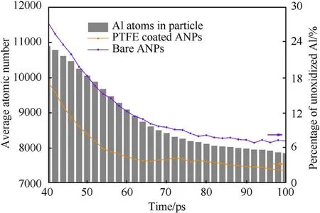
Fig. 8. Histogram of average Al atom number in PTFE coated ANPs and percentage of unoxidized Al atoms in both two cases from 40 to 100 ps.
However, such delay will not last for long. PTFE molecules continue to react with core aluminum atoms which diffuse to the surface in the combustion stage as shown in Fig.7(b).According to Fig.5(a),the sintering is fully developed after 100 ps for bare ANPs,which is considered as a liquid Al—O compound particle.Therefore,the diffusion coefficient of two kinds of aluminum atoms is proportional to the temperature and the curves are overlapped. For PTFE coated ANPs, two-thirds of core aluminum atoms left to maintain particle combustion and almost all shell aluminum atoms exist in the form of compounds which will be discussed in the next paragraph. The final average diameter of two coated particles is only 48.1 Å, smaller than 96.3 Å of sintered particle.
Another advantage of PTFE coating is that it greatly increases the reaction surface area of ANP by producing aluminum clusters.Most of aluminum atoms fall off from the surface exist in the form of clusters with different numbers of carbon and fluorine atoms.Additionally, the shrinkage of particle size is obvious and the oxidation rate of aluminum could be compared with bare ANPs by calculating the consumption rate of unoxidized aluminum.
Fig.8 shows the average number histogram of aluminum atoms in PTFE coated ANPs and the comparison plots of unoxidized aluminum content in the time span from 40 to 100 ps. During the heating stage, the aluminum consumption rate of bare ANPs is 132.15/ps which is lower than 161.75/ps for PTFE coated ANPs.The trend line of the average atomic number in the particle with time is also consistent with the active aluminum consumption line.Therefore,the decomposition of PTFE coating layer ensures that the aluminum atoms dispersed into the ambient environment can undergo more complete oxidation reactions, which promotes the ANP combustion in turn. In contrast, the oxidation process of sintered ANPs is related to the diffusion rate of oxygen atoms in the liquid particle. Due to the lack of means to disperse the oxidized aluminum atoms out of the particles, the final oxidation degree of sintered ANPs is only 0.3 times that of PTFE coated ANPs in the same time span.
Based on above analyses, in the double particle model, the key point to prevent ANP sintering is the contact area between PTFE and ANP surface. Coated PTFE molecules have more opportunities to react with alumina shell than the PTFE in gas state.However,in a real SP,ANPs are uniformly embedded in propellant matrix and it is predictable that the separated two ANPs would sinter with other adjacent ANPs.Sippel et al.carried out a comparative experimental study on PTFE modified ANP sintering [51]. In their results, PTFE modified ANPs effectively alleviated the sintering.The agglomerate sizes of PTFE modified particles is only 54.7 μm,whereas, 75.8 μm for spherical particles. Our simulation qualitatively reflects this trend in snapshots of Fig.5.The average diameter of two separated ANPs is 49.1 Å smaller than the initial diameter 82.8 Å.The process of PTFE coating layer reducing ANPs’ size will be discussed in the next section. Similar conclusions can also be found in other experiment work [52,53]. Furthermore, LIU et al.’s performed mesoscale simulations by using dissipative particle dynamics(DPD)method at 298 K and 678 K[54].They found raising temperature is helpful to the diffusion of PTFE and improve the miscibility of PTFE and ANPs. Such result is consistent with findings in Fig. 7(a). The rising rate of the orange line increases significantly after the temperature exceeds the melting point of PTFE(around 700 K,after 10 ps).Such phenomenon also indicates the molten PTFE coating layer promotes the movement of shell aluminum atoms.
3.2. Effect of ambient temperature on combustion configuration of PTFE coated ANPs
This section studies the effects of different ambient temperatures on the anti-sintering and combustion behaviors of PTFE coated ANPs. Based on retaining the same heating process as described in section 2.3, the temperature of the combustion stage under NVT ensemble is maintained at 1000,1500,2000,2700,3000 and 3500 K respectively.All these cases share a same initial model as shown in Fig. 4(a). Note that, all ANPs coated by PTFE are not sintered within 260 ps.In the supporting information,Fig.S2 shows the temporal plots of shrinkage ratio for cases under different combustion temperatures.
The RDF value is calculated as Eq. (3), where ρ is the system density (quantity density), N is the total number of atoms,T is the computation time (steps) and r is the radius away from the reference atom [47]. RDF is suitable to describe the certain atom distribution in a time span and dr here is selected as 0.1 Å.
Most of unoxidized aluminum atoms are beneath the shell and consist the core region. Therefore, the RDF pair of core aluminum and PTFE molecules could monitor the oxidation process of ANPs within the selected time span. For simplicity, simulations at different temperatures are named as case 1 to 5 sequentially in which case 1 represents two ANPs coated by PTFE heated and combusted at 1000 K. First concerned issue is how surface PTFE molecules decompose and diffuse during the heating stage.
Fig. 9(a) shows the RDF plots of core Al-surface PTFE pair of different cases (not including the ambient PTFE). All curves arise their first peak at 2.05 Å which is believed to be the average length of Al—F and Al—C bonds. The height of the first peak reveals the degree of combining of core aluminum and surface PTFE during the heating stage. With the increase of temperature, the more core aluminum atoms react with surface PTFE molecules. The second peak is not obvious for case 1 and 2, nevertheless, when heating temperature is greater than 2000 K, the peak becomes apparent and its peak value gradually approaches to 0.19. The second peak appears around 4.5 Å which is close to the initial coating layer thickness as described in section 2.2.According to the snapshots in Fig.5(b),the grafted PTFE molecules are the first part to fall off from the surface, however, the height of the second peak does not decrease with the increase of temperature.
Such changes for different cases illustrate the PTFE components stably adsorbed on the surface and the core aluminum atoms do opposite movements along the radial direction.When the distance is greater than 5 Å,practically no long-range order could be found and curves have an upward trend which indicates fallen PTFE molecules are in the gas state.Note that for case 1 and 2 the tail part is higher than the first peak value which means quite a few PTFE fall off without reacting with core aluminum atoms.
Fig.9(b)shows RDF plots of Al—Al pair for studying the effect of temperature on the configurations of ANPs and the time span is the last 50 ps of the combustion stage. It is clear that for cases with temperature lower than 2000 K,the RDF curve is characterized by periodic peaks within 15 Å.The first peak appears at 2.95 Å which is slightly larger than the length of Al—Al bond 2.85 Å at room temperature. Therefore, the first peak height reflects the degree of oxidation of ANPs and the higher the ambient temperature, the more aluminum atoms leave the particle surface. An approximate long-range order structure also indicates atoms in the core region do not fully participate in the reaction at low temperatures.
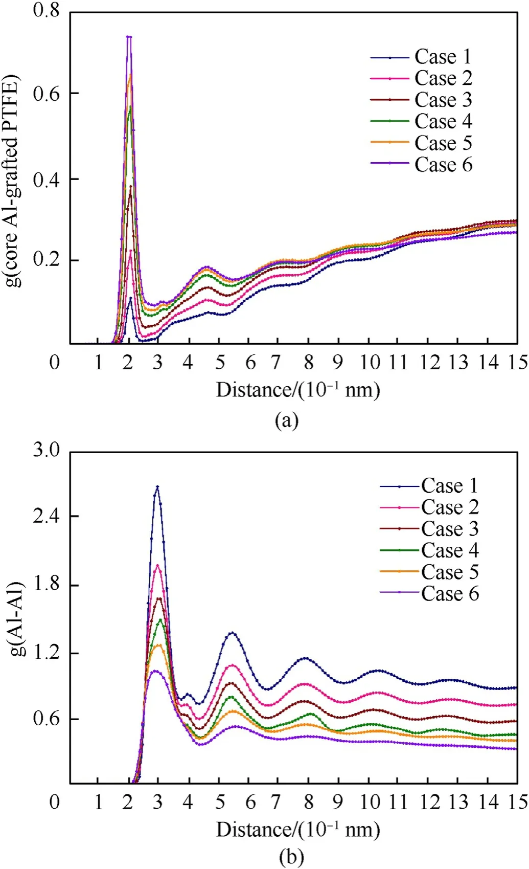
Fig.9. RDF plot of core Al-surface PTFE pair in the(a)heating and(b)Al—Al pair in the combustion stage.Case 1 to 5 represent the combustion temperature at 1000—3500 K.
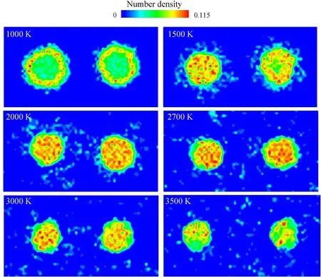
Fig.10. The final number density distribution of atoms belonging to ANPs at different combustion temperatures.
In order to further investigate the effect of temperature on the combustion morphology of PTFE coated ANPs, Fig. 10 shows the number density distribution of atoms belonging to ANPs in the final combustion stage.
Each picture in Fig. 10 is drawn according to the statistical average of the last 250 frames and before that, each system has already reached equilibrium states.Therefore,this series of pictures from 1000 K to 3500 K could be treated as the combustion evolution process for PTFE coated ANPs in SP. When the combustion temperature is maintained at 1000 K,the interface region between ANP shell and core has a larger atomic density than other regions.Because the temperature is higher than aluminum melting point but lower than the alumina melting point, with the outward diffusion of liquid aluminum atoms, the interface region becomes the main region of Al-PTFE reactions.
When the temperature rises to 1500 K, an obvious crown structure around the ANPs is observed. The high-density region at the shell-core interface disappears, instead, the density of the original core increases which indicates the main component of the core region is no longer liquid aluminum but alumina produced by the inward diffusion of shell oxygen atoms. Although fluorine is more oxidizing than oxygen, fluorine atoms prefer to disperse in outer space after reacting with surface aluminum atoms.
Almost no fluorine atoms remained in the particles according to the snapshot in Fig.5(b)(similar snapshots are identified for other cases). It is because of the gaseous characteristics of aluminum fluoride, and the decomposed PTFE coating layer shows a strong anti-sintering behavior. As the combustion temperature further increases, the diameter of particles shrinks, the crown structure disintegrated and more aluminum clusters of different sizes gradually fill the whole simulation box. The interval space between particles attains the maximum when the combustion temperature reaches 3500 K. The liquid particles after combustion are mainly composed of Al,O and C due to the relatively high boiling point of the compounds than aluminum fluoride.
Table 1 compares the change of particle size and shrinkage ratio with results from Ref.26.The ability of PTFE to oxidize the alumina shell makes the core aluminum atoms continuously diffuse to the surface and form gaseous AlF3. Therefore, the oxidation degree of ANPs varies with the combustion temperature, which indirectly affects the final shrinkage ratio.By contrast,Liu et al.used ethanol molecules to coat ANP and found there is little change in the particle size of two ANPs until the end of simulation[26].The ability of the coating material to oxidize alumina determines the potential of two particles to be further pushed away by gas products after they are separated by the initial surface repulsion. An organic material with weak oxidation can only slow down the sintering rate of ANPs by chemical adsorption, but cannot prevent the occurrence of sintering like PTFE discussed above.
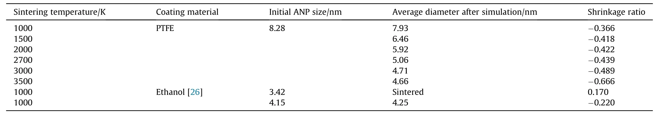
Table 1The change of particle size and shrinkage ratio after sintering simulation.
3.3. Comparative study of ANP with/without PTFE coating in fast ignition mode
In the experiment,there are various ways to ignite ANPs which can be distinguished by heating rates. Such as laser induced ignition usually achieve three orders of magnitude higher heating rate than the transfer rate in SP.Considering the diameter of ANPs here is far less than the real particles used in SP(50—80 nm),such ANPs are more likely to experience an instantaneous ignition process in which its temperature could be equal to the ambient temperature at the very beginning.In view of above points,a comparative study has been done to check the role of PTFE in fast ignition. The procedure of fast ignition is simpler than that described in section 2.3:the system only performs NVT ensemble simulation at 2700 K.
Different from heating system with a certain rate, a sudden volume rise of two particles is observed in the first few picoseconds as shown in Fig.11. All ambient oxidant molecules have been hidden for clarity and six representative time nodes are selected to demonstrate the sintering and combustion process. Generally, for bare ANPs, the formation of neck region and sintered particle are observed as discussed in section 3.1. PTFE coated ANPs maintain independent combustion after the distance between mass centers stable around 115 Å. Because 2700 K is higher than the melting points of aluminum and alumina,both core and shell parts turn to liquid state from the beginning. For bare ANPs, due to the volume expansion, the neck region grows rapidly and fuses the left and right particles together in just 6 ps which is 28 ps earlier than sintering-combustion simulation shown in Fig. 5(a). From snapshots we can see alumina shell decomposes with absorbed PTFE violently.A considerable number of Al—F compounds do not form a stable neck region like bare ANPs,but continue to diffuse outward at a high speed.The reaction energy between PTFE and ANPs gives these atoms enough kinetic energy to move and push away particles.

Fig.11. Snapshots of (a) bare ANPs and (b) PTFE coated ANPs at different time nodes.
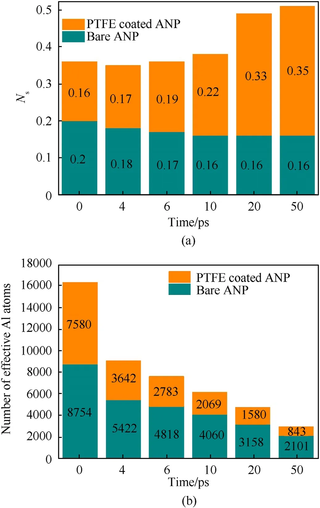
Fig. 12. Histogram of (a) number of atoms per unit surface area Ns and (b) effective aluminum content at the corresponding time nodes.
Fig. 11(a) demonstrates that, at a temperature higher than alumina melting point, adjacent ANPs will sinter quickly without mutual movements.Because the core-shell models of ANPs are the same,their expansion ability should also be the same at 2700 K.In order to study the change of reaction contact area caused by volume expansion, defineNsas the total number of surface atoms(belong to ANP) divided by the surface area and Nsrepresents the effective reaction area of ANPs with ambient oxide molecules at different time nodes.The surface area is calculated by using alphashape method[55].The probe sphere radius parameterRαis a key parameter in calculating the surface in alpha-shape method which is selected as 2.95 Å,according to the first RDF peak value.The RDF plot of Al—Al Pair could be found in the supporting information Fig. S3.
In Fig.12(a),bare ANPs have a larger Nsvalue than PTFE coated ANPs at the beginning because PTFE coating layer forms the outer surface in the latter case.As sintering process goes,two bare ANPs start to sinter together which reduces their surface area and the number of surface atoms almost remains constant. In the end, theNsof bare ANPs converges to the value of 0.16 which is little different from the initial configuration. For PTFE coated ANPs, the Nsvalue increases gradually in the first 10 ps owing to it is a period of PTFE molecules reacting and diffusing outward with surface atoms. When the alumina shell is stripped from the core, the surface area increases immediately. Aluminum atoms from decomposed alumina shell are not solid state but maintain gas state which further increases the effective reaction area. In the last 20 ps, the system is full of Al—F compounds and the Nsvalue exceeds 0.3 which is corresponded to the findings in snapshots. Subsequently,the content of effective aluminum is also counted in Fig.12(b) according to the criterion set in section 3.2. Although the consumption rate of effective aluminum atoms is similar in the first 10 ps,the PTFE coated ANPs show a greater potential to convert aluminum atoms to oxidized state.
Fig.13 shows the diffusion coefficient analysis for core and shell aluminum atoms of two cases.The diffusion coefficient reflects the movement ability of four groups of atoms.No matter what type of aluminum atom, the curve experiences a rapid rising period in 1.4 ps.Accordingly,the diffusion coefficient reaches the peak value 3.8,2.6,2.8 and 2.6 for core aluminum,shell aluminum in bare ANP and the counterpart in PTFE coated ANP respectively. As trajectory snapshots shown in Fig.11, the initial thermal expansion results a rapid increase in the movement rate of aluminum atoms.However,the core aluminum atoms in bare ANP shows the highest peak value which is hard to explain by phase transition theory due to the same system temperature and the region volume. Therefore, the PTFE coating layer should be responsible for the different peak values of diffusion coefficient in core aluminum atoms:The existence of PTFE coating layer hinders the thermal motion of core aluminum atoms.In other words,the shell composed by PTFE and alumina will be less prone to be deformed than pure alumina shell. After 1.4 ps, all curves decrease rapidly and reach their valley point in 3.6 ps because the particle melting process is completed. Subsequently,the diffusion coefficients of aluminum atoms in bare ANP enter a stage of slow rising and finally converge after 45 ps. However, for PTFE coated ANP, shell aluminum atoms take the lead to vigorous motion because the heat generated from PTFE and alumina reactions accelerates atomic motion and take them to ambient space as clusters. As more core aluminum become surface atoms, the diffusion coefficient of them gradually increases and becomes 1.86 times higher than that of bare ANP in the end.
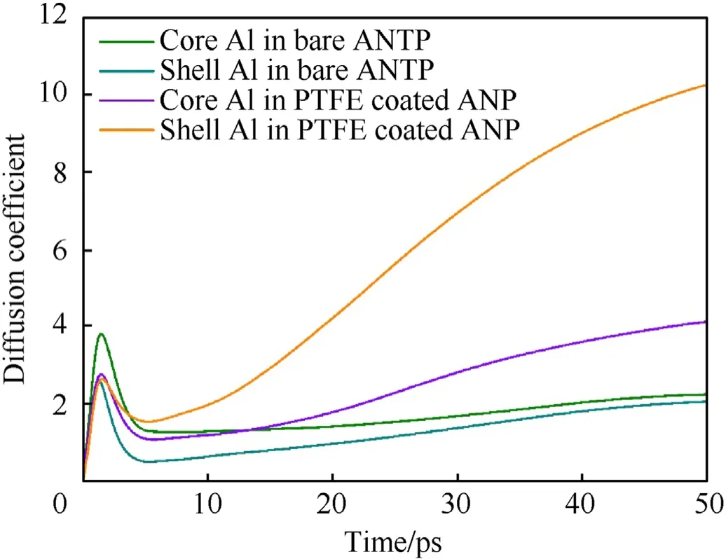
Fig.13. Curves of diffusion coefficient versus time of core and shell aluminum atoms in fast ignition simulation.
4. Conclusions
Reactive molecular dynamics simulations have been performed to investigate the role of PTFE coating layer in anti-sintering and promoting ANP combustion.The PTFE coating layer is characterized as the inner chemisorption and the outer grafted structure.During the heating process, bare ANPs are sintered in the order of core melting, neck region formation and liquid atoms diffusion. PTFE coating layer could prevent particles sintering at any temperature for following points:
(1) The intimate contact of PTFE coating layer ensures the alumina shell could be decomposed into small Al—F clusters and the falling PTFE molecules in heating stage endow two ANPs initial opposite velocities;
(2) After entering the combustion stage, the particle size decreases with the reaction of ANP and PTFE. The number of atoms in particle decreases from 10,800 to 7854. Compared with bare ANPs, the percentage of effective aluminum in PTFE coated ANPs is 0.3 times less than that of bare ANPs.
(3) The diffusion coefficient of Al—F compounds is higher than alumina at the same temperature which prevents the formation of neck region but push away adjacent particles.
Combined with RDF and number density analysis, when temperatures below 2000 K, the diffusion mechanism dominates the combustion process of ANPs. Temperature greater than 2000 K is necessary for PTFE coating layer accelerating combustion process by producing small aluminum clusters.
In fast ignition simulations,neck region of bare ANPs is formed in the first 8 ps and the production of solid-liquid mixture limits its further oxidation. The generation of small aluminum clusters makes the Nsvalue of PTFE coated ANPs reach 0.35,which is twice higher than that of bare ANPs. The analysis of aluminum diffusion coefficient indicates the shell coated by PTFE is not easy to be deformed by internal thermal expansion compared with pure alumina shell in the first 5 ps. However, as shell aluminum atoms diffuse into the outer space,the diffusion coefficient of core atoms becomes higher than that of bare ANPs after 13.4 ps. This work is expected to provide data and reference for further research on sintering of multi ANPs with/without different coating layer.
Declaration of competing interest
The authors declare that they have no known competing financial interests or personal relationships that could have appeared to influence the work reported in this paper.
Acknowledgements
This work is supported by the fellowship of China Postdoctoral Science Foundation (Grant No.2021TQ0267). Thanks to Gengzi for providing high performance computing resources.
Appendix A. Supplementary data
Supplementary data to this article can be found online at https://doi.org/10.1016/j.dt.2022.03.010.
杂志排行

Defence Technology的其它文章
- Defence Technology
- Joint target assignment and power allocation in the netted C-MIMO radar when tracking multi-targets in the presence of self-defense blanket jamming
- Design and dynamic analysis of a scissors hoop-rib truss deployable antenna mechanism
- Structural design and modal behaviors analysis of a new swept baffled inflatable wing
- Cooperative trajectory optimization of UAVs in approaching stage using feedback guidance methods
- An improved four-dimensional variation source term inversion model with observation error regularization