Cooperative trajectory optimization of UAVs in approaching stage using feedback guidance methods
2023-07-04HaoranShiFaxingLuLingWu
Hao-ran Shi, Fa-xing Lu, Ling Wu
College of Weaponry Engineering, Naval University of Engineering, Wuhan, 430033, China
Keywords:Unmanned aerial vehicles (UAVs)Target tracking Trajectory optimization Receding horizon optimization (RHO)Feedback guidance method
ABSTRACT
1. Introduction
Research on hypervelocity projectile has been dramatically promoted with the advantages of long-range, sizeable kinetic energy,and low cost.Accurate target indication technology is the key to determining whether a hypervelocity projectile can accurately strike a remote target in real-time. Unmanned aerial vehicles(UAVs) are widely used in intelligence surveillance, search and rescue, reconnaissance, and other aspects because of concealed action, low cost, and high safety. Thereby, it has the potential to provide an accurate position of the remote target for hypervelocity projectiles[1].Compared with a single UAV,multi-UAV cooperative target tracking can effectively enhance tracking robustness and improve tracking accuracy [2,3]. An essential goal of multi-UAV cooperative target tracking is to enhance the target state estimation by studying the UAV-target geometry to improve the quality of the UAV observation information[4,5].In this paper,we investigate a cooperative control algorithm for UAVs with approaching formation to improve the tracking accuracy of the remote target by placing UAVs in the optimal observation positions.
How to control UAVs in optimal observation positions is essentially a trajectory optimization problem. There are generally three approaches used to optimize UAV trajectories for target tracking.One approach is to develop parameterization methods to transform the optimal control problem into a nonlinear programming problem, and the optimal trajectory is obtained by numerically solving nonlinear programming problems.Oshman addressed the optimization trajectories for fixed-target localization based on maximizing the determinant of the Fisher information matrix(FIM),and the differential inclusion method,gradient method,and orthogonal parameterization method were introduced to solve the optimal control problem [6]. Ponda and Grocholsky [7,8] used sequential quadratic programming(SQP)and the gradient descent method to optimize the trajectory.A gradient search algorithm was developed to deploy the optimal placements by minimizing the trace of the inverse FIM in Ref. [9]. In Refs. [10—12], the receding horizon optimization (RHO) method was presented to plan the observed trajectories.The interior-point method was used to obtain the optimal trajectory for a single UAV tracking target in Ref. [13].Zhang et al. [14] developed a sequential convex programming method for nonlinear optimal control problems in UAV path planning. Uluskan [15] provided a numerical noncausal trajectory optimization method for target localization. However, traditional methods such as the gradient,interior-point,or SQP have been used to solve the trajectory optimization problem of target cooperative tracking [16], easily falling into local optimization.
The second approach is to use the optimal control method.Ousingsawat et al. [17] developed a receding horizon optimal control formulation to solve UAV trajectories based on FIM determinants.Kim S.et al.[18]obtained the optimal observation and achieved stable tracking by controlling the phase of the UAV with the variation method.Zhu et al.[19]proposed distributed nonlinear model predictive control to realize cooperative standoff target tracking by two UAVs.In Ref.[20],bang-bang control was utilized to present the optimal trajectory with a minimum Cram′er-Rao lower bound (CRLB) for target tracking. Although the accuracy of the solution obtained by the optimal control method is high, it is sensitive to the initial value and has difficulty dealing with complex constraints.
The third approach is to design a cooperative control algorithm based on optimal sensor placement analysis results,and a guidance method is generally adopted. The advantages of this method are simple calculation, good real-time performance and insensitive to initial values. But the main disadvantage is that the design of guidance law is difficult and the scalability of the algorithm is poor.Eric W.Frew et al.[21,22]used the Lyapunov guidance vector field(LGVF) to control multi-UAVs maintain standoff tracking of stationary and moving targets. Seunghan Lim et al. [23] presented strategies for standoff target tracking by a team of unmanned aircraft using a vector field. Jung W et al. [24] proposed path following,arrival position,angle,and time control using the vector field approach.Zhao et al.[25]proposed an artificial potential field method to deploy optimal sensors placements autonomously. In Ref.[26],a guidance law was developed using differential geometry to complete cooperative standoff tracking.Yao et al.[27]proposed a hybrid potential field approach to solving the problems of target tracking and obstacle avoidance. Kokolakis et al. [28] developed a guidance law to realize robust standoff target tracking.Although a trajectory optimization method based on the guidance method is simple and easy to implement, to the best of the authors’ knowledge, most studies have only focused on target tracking in the hovering phase,and less attention has been given to target tracking in approaching stage. For the target within 10 km, UAV can maintain standoff tracking of the target,however,UAVs cannot maintain standoff tracking of the remote target about 100 km in practical applications. Although Andrew J. Sinclair et al. [29] proposed a suboptimal feedback guidance law that keeps the sight-of-angle between two UAVs and target at 90◦while ensuring that the UAV approaches the target, this method takes a long time to form the optimal observation configuration, and only the cooperative guidance law of two UAVs is designed.

Motivated by the previously mentioned aspects, this paper focuses on the optimal observation trajectory of multi-UAVs for remote target tracking in approaching stage using the feedback guidance method. First, the multi-UAV target tracking problem is modeled, and then optimal trajectory trends of UAVs are analyzed theoretically. Additionally, we summarize the optimal observation configuration of multi-UAV in the approaching target phase. Second, a feedback guidance method is designed based on the observation configuration with approaching formation, and it is proven that the designed guidance law can stabilize the UAV in the optimal observation configuration. Third, the optimization ability and estimation performance of the feedback guidance law are compared and simulated, and the effectiveness of the proposed method is validated. Overall, the main contribution of this paper compared with the previous work can be represented as follows:(1)The trend of the optimal trajectory is analyzed theoretically for multi-UAVs cooperative target tracking in approaching stage. (2)The proposed feedback guidance method is superior to the other methods in terms of stability, applicability and real-time. (3) A sufficient condition for the stability of the feedback guidance method is presented.
The structure of this paper is as follows. Section 2 models the target tracking problem of multi-UAVs. Section 3 discusses the optimal observation trajectory trend of multi-UAVs in approaching stage. Then, the feedback guidance method is proposed for planning the optimal trajectory, and a sufficient condition for global stability is presented in Section 4.Section 5 conducts simulations to verify the effectiveness of the proposed algorithm. Finally, conclusions and future work are discussed in Section 6.
2. Models and problem formulation
2.1. Problem description
The scenario of cooperative UAV target tracking in approach stage is shown in Fig.1. In Fig.1, OXY stands for the reference coordinate system.(xi,yi)represents the position of UAVi,and(xt,yt)represents the position of target.viindicates the speed of the UAVi.The heading angle ψiand the measurement angle θiof the target by theith UAV are illustrated in Fig. 1 δ12is the line-of-sight angle between UAV1, UAV2 and the target, δ1iis the line-of-sight angle between UAV1, UAViand the target. As shown in Fig.1, each UAV measures the position, speed and other information of the target from different observation directions, and then obtains relatively accurate target state information through filtering and estimation.The key for cooperative UAV target tracking is to place UAV in the optimal observation position. The trajectory of the UAV is usually optimized by maximizing the Fisher information matrix in approaching stage, which is generally solved by the gradient method and heuristic method. However, the gradient method is sensitive to the initial value and has poor stability. The heuristic method has poor real-time performance.Therefore,it is necessary to propose an optimization algorithm that meets both stability and real-time performance.
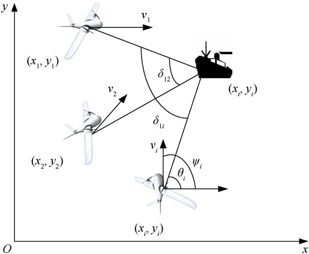
Fig.1. Geometry between UAVs and the remote sea target.
The key to using the feedback guidance method to plan trajectory is to solve the following two problems. (1) Determining optimal observation trends of multi-UAVs in approaching stage.(2)Ensuring that the designed guidance law can stabilize the UAV in the optimal observation position.
2.2. UAV model
It is usually assumed that the UAV is a mass point in the study of coordinated control problems, and each UAV has a low-level flight controller (autopilot) that controls the flight course of the UAV through its heading angle. Owing to the UAV approaches the optimal configuration as soon as possible, the UAV moves at the maximum speed in approaching stage.Consider a two-dimensional UAV kinematic model[10]flying at a constant altitude and speed as
wherexi,yi,ψi,virepresent the inertial position,heading angle and speed of the UAVi, respectively. With the UAV speed unchanged,the UAV plans trajectory by changing the heading angle to achieve better observation.
2.3. Target model
To achieve accurate tracking of the target,it is necessary to know the target's movement, which helps track the target better. A remote target at sea is mainly aimed at the relatively slow-moving target such as a warship.
(1) When the target performs uniform linear motion,the target's motion model in the two-dimensional plane is established.x(k)=[x(k), ˙x(k),y(k), ˙y(k)]Trepresents the state of the target at timek, which includes position and speed, and then the system state can be expressed in the following formwhereTsis a sampling time, w(k) is Gaussian process noise with zero mean, and the covariance matrix of proces noise is Q(k).
(2) When the target performs maneuvering motion, a maneuvering target tracking method based on Singer model is introduced and x(k)=[x(k), ˙x(k),¨x(k),y(k), ˙y(k),¨y(k)]Trepresents the state of the target at timek.
Discretized system equations for the acceleration model are expressed as
where η(k) is a process noise that represents the acceleration characteristics of the target.The state transition matrix F(k)can be represented as follows:where α is the parameter describing the accelerated motion of the target, the smaller α represents the slow maneuver of the target,and the larger α represents the relatively fast maneuver of the target.
The covariance matrix of process noise q(k) is
wherel=e-2αTs,m=is expressed as acceleration variance,which is determined by the maneuvering characteristics of the target.
2.4. Sensor model
The target's observation information must be obtained as much as possible to realize the accurate indication of the over-thehorizon target, so the sensor system based on angle and range measurements must be adopted.The measurementzof the sensor can be modeled according to the position of the UAV(x,y)Tand the target position(xt,yt)Tas follows:
whereh(xk,xt,k) represents nonlinear observation function of the UAV (xk) relative to target (xt,k) at timek, v(k) is gaussian measurement noise with zero mean,the measurement noise covariance matrix is R(k),σrandσθmean standard deviation of the range and bearing for the UAV measurement noise,respectively.
2.5. State prediction by extended information filtering (EIF)
Compared with the extended Kalman filter (EKF), EIF can directly add the information matrix for data fusion. Each sensor node only needs to generate an information matrix,and the global information estimation can be obtained by simple algebraic addition at the fusion center. The state estimate ^xand covarianceP are used in EKF, which are replaced by the information state ^yand information matrix Y in the information form. The information state and information matrix are defined as^y =P-1^x,Y = P-1.EIF includes prediction process and the estimation process as follows[30]:
(1) Prediction process
(2) Update process
2.5.1. Estimate state
3. The analysis of optimal trajectory trends
Cooperative target tracking of multi-UAVs mainly involves two aspects: one is the method of target state estimation and information fusion;The second is the trajectory optimization algorithm.Compared with the previous work, this paper designs cooperative tracking control algorithms of multi-UAVs based on the feedback guidance method. The algorithm mainly includes two parts. The first part is the trend of UAV optimal observation trajectory, as shown in Section 3; The second part is to design the cooperative control algorithm based on the optimal trajectory trend, as shown in Section 4. The flowchart of cooperative trajectory optimization using feedback method is shown in Fig. 2.

Fig. 2. Flowchart of cooperative trajectory optimization using feedback guidance method.
In this section,we will discuss the optimal observation trend of multi-UAVs in the approaching target phase.To solve this problem,we introduce FIM, which characterizes the amount of information about the target state.It is assumed that the sensors carried by the UAV have the same measurement variance and are the range and azimuth variance of the sensor, respectively.
3.1. Optimal trajectory trends of two UAVs
The total FIM of two UAVs can be expressed as
For sensor model with angle and rang measurement, its Jacobian formula is as follows:
where θiis the measurement angle of UAVirelative to target,riis the distance between UAViand the target.
According to Eq.(12)and Eq.(13),we can get the determinant of FIM of two UAVs
where δ12is the line-of-sight angle between UAV1, UAV2 and the target as shown in Fig.1.Definethe determinant of FIM is calculated by
Eq. (15) is divided into two partsandNote that the functionis always positive, whilechanges sign depending onIn the case ofthe biggeris,the greater the impact of δ12on det(J2).On the contrary, the smalleris, the lesser impact of δ12on det(J2).In this case,the determinant of FIM is maximized when the line-of-sight angle between UAVs and the target is 90◦(δ12=π/2).In the case of= 1, the line-of-sight angle between UAVs and the target (δ12) has little effect on the optimal trajectory.
In practice, the ranging accuracy of the sensor can reach less than 10 m,the angle accuracy is generally not higher than 0.1◦,andfor remote target. Based on the above analysis, δ12is the main factor affecting the size of det(J2) in the situation ofand the optimal trajectory trend is that the UAV performs triangulation first and then moves toward the target after form the optimal configuration of δ12=π/2.
3.2. Optimal trajectory trends of three UAVs
The total FIM of three UAVs can be expressed as
According to Eq. (13), we can obtain
where Γ={(i,j)}represent all combinations ofiandj,i,j∈{1,2,3}andj>i.
Eq.(17)is divided into two partsIn the case of,the biggeris,the greater the impact of δ12,δ13,δ23on det(J3). On the contrary, the smalleris,the lesser impact of δ12,δ13,δ23on det(J3).In this case, the determinant of FIM is maximized when the line-of-sight angle between UAVs and the target is 120◦or 60◦. In the case of, the line-of-sight angle between UAVs and the target has little effect on the optimal trajectory.δ12,δ13,δ23is the main factor affecting the size of det(J3)in the situation of ^R1,^R2,^R3>10,and the optimal trajectory trend is that the UAV performs triangulation first and then moves toward the target after form the optimal configuration of δ12=π/3,δ13= 2π/3,δ23=π/3.
3.3. Optimal trajectory trends of multi-UAVs
The FIM of multi-UAVs can be computed by the following algebraic relationship [31].
whereNrepresents the number of UAVs.
From Eq.(18),the determinant of FIM of multi-UAVs is given by
wherei,j∈{1,˙˙˙,N}andj>i.
Note that sin2δijbecomes the main factor influencingasgrows.UAVs trend to perform the optimal configuration first and then move toward the target whenNext, we will concern the optimal configuration of UAVs.
From Eq.(20),it is readily observed that the det(JN)reaches its global minimum assin2δijreaches its global maximum in the case ofA placement is optimal ifN(N>3)UAVs are located at the vertices of an n-side regular polygon as shown in Fig. 3 [32].
UAVs cannot move around the remote target in practical applications,and UAVs'placement in Fig.3 is not suitable.However,the symmetrical transformation of the UAV position centered on the target position does not change the determinant of FIM[31].Based on this property, optimal placements of UAVs with approaching formations are shown in Fig. 4.
4. Feedback guidance methods
4.1. Feedback guidance law of two UAVs
In the optimal trajectory of multi-UAVs cooperative target tracking, the heading angle of the UAV needs to be designed to make the UAV approach the target and form the optimal observation configuration. According to the analysis in subsection 3.1, the optimal trajectory of two UAVs is that the line-of-sight angle between UAVs and the target approaches 90◦.The following feedback guidance law of two UAVs is designed.
where the proportional coefficientki>0(i= 1,2). The largerki(i=1,2)is,the more the UAV move toward the target(ri→0)at first, the smallerki(i=1,2) is, the more the UAV prioritize form triangulation (δ12→90◦) at first.
Here, two technical theorems (Theorems 1 and 2) are given,which are used to ensure that feedback guidance law(21)can make the UAV approach the target and form the optimal observation configuration, and the corresponding proofs are presented.
Theorem 1.When0<(i=1,2),the feedback guidance lawofEq. (21)makes the UAV approach the target.
Proof.Using Eq. (8), we can show that
To describe Eq. (22) in terms of polar coordinates
Take UAV1 as an example
Sincewhen0Bysubmittingthisinto Eq.(25),thenthe UAV1approaches the target.Similarly,itcan be proventhat UAV2 approaches thetarget when.Thus,the proof is completed.
Theorem 2.When0<π(i= 1,2),δ12=π/2is the globallyasymptotically stable equilibrium point of the feedback guidance law ofEq. (21).
Proof. See Appendix A.appsec1
Theorem 1 and Theorem 2 ensure that the feedback guidance law of Eq.(21)can make the UAV approach the target and form the optimal observation configuration.
4.2. Feedback guidance law of three UAVs
The optimal trajectory of three UAVs tends to form the optimal configuration first,hence,we propose a two-layer guidance law for three UAVs cooperative target tracking.
In the first stage, the feedback guidance law is designed as
When the line-of-sight angle between UAV1 and UAV3 reaches π/2, the UAV performs the second stage of the feedback guidance law, which is designed as
where the proportional coefficientki>0(i= 1,2,3).
The desired trajectories for UAVs should approach the target and form an optimal formation, and spiraling trajectories are not expected,so it is crucial to determine that the design of the feedback guidance law can meet the requirements. The feedback guidance law in the first stage separates the angle of the UAV, and the guidance law in the second stage makes the UAV form the optimal observation configuration, so the following two theorems are introduced.
Theorem 3.When0<(i= 1,2,3),the feedback guidancelaw ofEq. (27)makes the UAV approach the target.
Proof.Taking UAV1 as an example, from Eq. (22),
Theorem 4.When0<π(i= 1,2,3),δ12=π/3,δ13=2π/3is the globally asymptotically stable equilibrium point of the feedback guidance law ofEq. (27).
Proof.See Appendix B.
Theorem 3 and Theorem 4 ensure that three UAVs approach the target and achieve the optimal observation configuration.It is also important to note that if the spiraling trajectories of UAVs approach the target, the azimuth angle is constantly changing. Eq. (A2)shows, however, that ˙θ=0 for θ = ψ, which means that the azimuth angle is a constant,and undesirable spiraling trajectories will not appear.
4.3. Feedback guidance law of multi-UAVs
In subsection 3.3, the optimal configuration and optimal trajectory trends of multi-UAVs with approaching formation are analyzed detailed. Take four UAVs as an example to illustrate the design of multi-UAVs feedback guidance law in this section. The optimal geometric configuration of the four UAVs is that the two groups fly to the target at 90◦, and the feedback guidance law is displayed as follows.Similar as two UAVs and three UAVs, the following two theorems prove the stability of Eq. (29).
Theorem 5.Whenπ(i= 1,2,3,4),the feedback guid-ance law ofEq. (29)makes the UAV approach the target.
Proof. Taking UAV1 as an example, it can be known from Eq.(22).
Theorem 6.When 0π(i=1,2,3,4) andk2=k3,δ12=δ14=δ32=π/2,δ13=0is the globally asymptotically stable equilibrium point of the feedback guidance law ofEq. (29).
Proof.See Appendix C.
5. Simulation analysis
To verify the effectiveness of our method proposed in this paper,this section presents simulation experiments. It is simulated in MATLAB R2020a on the computer with CPU processor of Intel Core i7 and dominant frequency of 1.6 GHz. First, simulation experiments are implemented to evaluate the performance of the feedback guidance method compared with the RHO method. Then,simulation experiments are carried out to examine the state estimation of the proposed feedback guidance method compared with the LGVF algorithm. Finally, the simulation experiment ofmaneuvering target tracking is carried out to examine the proposed feedback guidance method.
The target's initial position is located at(80000 m 80000 m)and the simulation last for 1500 s, the sampling timeTs= 1 s. The initial position,speed,and performance parameters of the UAV are shown in Table 1.

Table 1Initial state and performance of UAVs.
The root-mean square error (RMSE) is used as the evaluation index for the simulation results and is defined as
wherenis the number of trials, ^xmis the estimated state of the target at themth trial andxindicates the real state of the target.200 Monte Carlo trials are performed in this section.
5.1. Comparative experiment of the feedback guidance method and the RHO algorithm
To evaluate the performance of the feedback guidance method,the feedback guidance method is compared with the RHO method in this section. The determinant of the covariance matrix Y can more comprehensively reflect the precision of the observation position,maximizing the determinant of the covariance matrix Y is equivalent to minimizing the average estimated covariance.Therefore,the determinant of the covariance matrix is optimized to plan the UAV cooperative detection trajectory.
It is impractical to optimize the trajectory during the whole process, and the RHO method can effectively use the predictive information of the target to optimize the future UAV trajectories with a finite horizon. Therefore, the RHO method is used to solve the optimal control. Combined with the RHO method, the multi-UAV cooperative target tracking problem is transformed into a problem of optimal control that minimizes the objective function subject to constraints. The mathematical model is as follows:
whereNpis the receding horizon. The control input here is the heading angle ψiof each UAV by subsection 2.1.Thus,target motion,UAV motion,sensor model constitute Eq.(33).The indirect method[18] is utilized here to solve this trajectory optimization problem.
To compare the effectiveness of the proposed cooperative control algorithm, using the feedback guidance method and RHO method to optimize UAV trajectory.It is assumed that the target is moving with a constant speed at 6 m/s,the mean square deviation of the velocity noise is 0.01 in the horizontal and vertical directions,and the target's initial position is located at (80000 m 80000 m).The receding horizon is set asNp= 9.
5.1.1. Cooperative trajectory optimization of the feedback guidance method and the RHO algorithm
Using the feedback guidance for the cooperative tracking target of two UAVs,the optimal trajectory of the UAV gives priority to form triangulation,so it requires a largerki,e.g.,k1=k2=1˙5 is chosen,the simulation results are shown in Fig.5.The resulting trajectories are shown in Fig.5(a),and the line-of-sight angle between the UAVs and the target is shown in Fig. 5(b). By Fig. 5(a), the optimal observation configuration is formed while approaching the target,which is beneficial for observation. Fig. 5(b) shows the geometric configuration of the UAV,and the target is maintained at 90◦,which is consistent with the theoretical analysis in subsection 3.1.
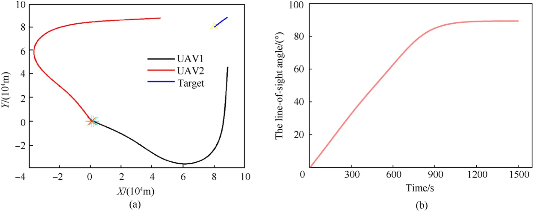
Fig. 5. Feedback guidance method: Cooperative target tracking of two UAVs, (a) Cooperative tracking trajectories; (b) The line-of-sight angle between UAVs and target.
Fig. 6 shows the cooperative tracking trajectories and the lineof-sight angle of two UAV using the RHO method. Compared with the simulation results of the feedback guidance method and the RHO method, the proposed feedback guidance method has a similar planned trajectory as the RHO method. In Fig. 5(a) and Fig.6(a),the trajectories of the proposed method and RHO method are different in the process of UAV moving from angle separation to approaching target, and the proposed feedback guidance method yields smoother curves, while they vary sharply for the RHO method.Since the RHO algorithm is based on the optimal solution,the trajectory of UAV planned by the RHO method can form the optimal configuration faster than the feedback guidance method.The comparison of the curves in Figs. 5(b) and Fig. 6(b) also confirms this conclusion. The RHO method forms the line-of-sight angle of 90◦earlier than the feedback guidance method.
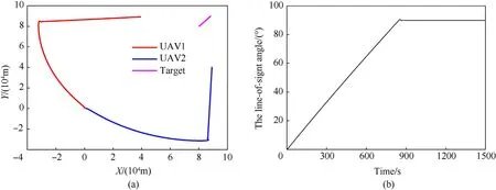
Fig. 6. RHO method: Cooperative target tracking of two UAVs: (a) Cooperative tracking trajectories; (b) The line-of-sight angle between UAVs and target.
For the case of three UAVs,the choice ofk1=1˙6,k2=1˙58,k3=1˙6 generates the trajectories shown in Fig. 7(a), and the line-ofsight angle between the UAVs and the target is shown in Fig.7(b).In Fig.7,the proposed trajectory optimization algorithm of three UAVs can guidance the UAV approach the target and form the optimal observation configuration of δ12=π/3,δ13= 2π/ 3.
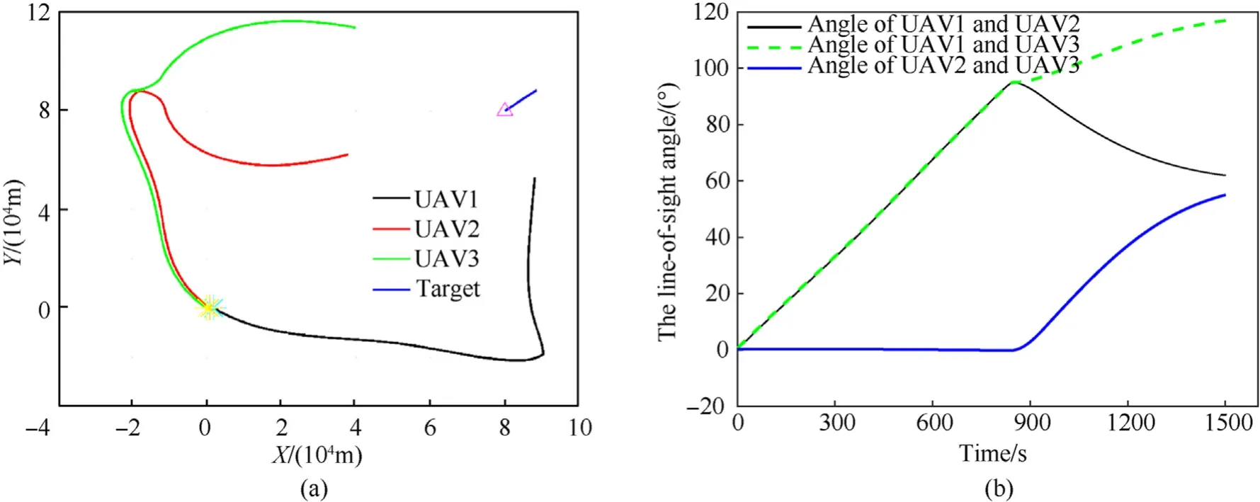
Fig. 7. Feedback guidance method: Cooperative target tracking of three UAVs, (a) Cooperative tracking trajectories; (b) The line-of-sight angle between UAVs and target.
Fig. 8 shows the cooperative tracking trajectories and the lineof-sight angle of three UAVs using the RHO method. Compared with the simulation results of Fig. 7(a) and Fig. 8(a), the proposed feedback guidance method has a similar planned trajectory as the RHO method. Fig. 7(b) and Fig. 8(b) show that since the RHO algorithm is based on the optimal solution,the RHO method can form the optimal observation configuration earlier than the feedback guidance method.
Considering the scenario of cooperative target tracking with four UAVs. Settingk1=k2=k3=k4=1˙6 and the simulation results are shown in Fig. 9. In Fig. 9, the proposed trajectory optimization algorithm of four UAVs can guidance the UAV approach the target and form the optimal observation configuration of δ12=δ14= δ32= π/2,δ13= 0. Fig. 10 shows the cooperative tracking trajectories and the line-of-sight angle of four UAVs using the RHO method.Compared with the simulation results of Fig.9 and Fig.10,the proposed feedback guidance method has a similar planned trajectory as the RHO method.
5.1.2. Performance comparison of the feedback guidance method and the RHO algorithm
To illustrate the ability of the two algorithms to obtain information, information entropy is analyzed and the information entropy is defined as Eq. (34).
Fig.11 shows the information entropy of the two methods, the information entropy of the feedback guidance method is within 0.339%of the information entropy found using the RHO method for coordinated target tracking by two UAVs, and the information entropy is within 0.153% for three UAVs, which indicates that the feedback guidance method and the RHO method have approximately the same trajectory optimization ability.
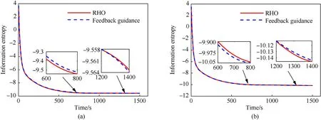
Fig.11. Information entropy compared by the RHO method and feedback guidance method: (a) Information entropy of two UAVs; (b) Information entropy of three UAVs.
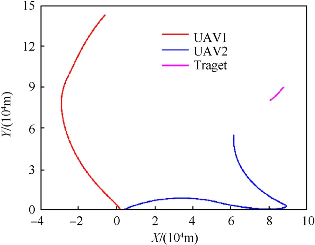
Fig.12. RHO method: improper selection of the initial value.
However,due to the complexity of RHO calculation,if the setting of initial control input is unreasonable,it may cause the divergence of UAV trajectory and resulting in the UAV moving away from the target as shown in Fig. 12. In Fig. 12, UAV1 is getting farther and farther away from the target, which obviously affects the observation of the target by UAV1, resulting in low tracking accuracy of the target.Additionally,this method has difficulty solving problems with multiple constraints and complex environments, which can only deal with simple cases,and the applicability of the algorithm is poor. The global stability of the proposed method is proved theoretically, which has good stability. We simulated several groups of different initial positions of UAVs to verify the stability of feedback guidance method. The simulation result is shown in Fig.13. From Fig.13,each group of UAVs can move toward the target and form an optimized observation configuration.
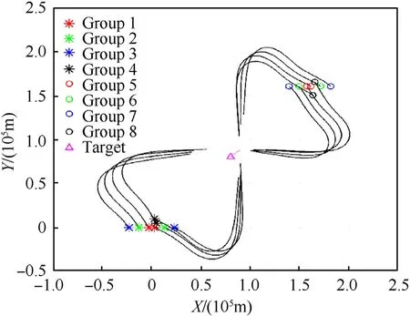
Fig.13. Different initial positions of UAVs.
To compare the real-time performance of the two algorithms,the average time consumption of the algorithm is evaluated. The average time consumption of the algorithm refers to the time taken by the algorithm to run once,and the results are shown in Table 2.Table 2 shows that the average time consumption of the feedback guidance method is much less than that of the RHO method.This is because the feedback guidance method only needs to calculate the guidance law at each moment,which is easy to obtain,and does not require calculating the numerical solution of trajectory optimization, so it has better real-time performance. The main reason why the time consumption of three UAVs is significantly bigger than that of two UAVs and four UAVs is that three UAVs design a two-stage feedback guidance law e.g. Eq. (26) and Eq. (27), while two UAVs and four UAVs only design a feedback guidance law e.g.Eq.(21)and Eq. (29), respectively.

Table 2The average time-consuming of the algorithm.
As mentioned in Section 3, the relative distanceaffects the optimal trajectory,Fig.14 displays the optimal trajectories of UAVs with={4,4˙5,7,20} using the RHO method. In Fig.14, the balance between moving toward the target and triangulation differs based onWhenis small,the initial UAV motion moves toward the target. Asgrows, the UAVs tend to perform triangulating at first.Fig.15 displays the optimal trajectories of UAVs with different proportional coefficientski. Trajectories show similar trends to Fig.14 for two or three UAV target tracking.These results show that the feedback guidance law can be tuned to obtain a performance very close to the optimal solution for some specific situations. In practical applications,when the distance between the UAV and the target, i.e.ris small, and the angle measurement accuracy of the sensor is low,i.e.σθis small,a smaller value ofkishould be selected.On the contrary, a larger value ofkishould be selected.
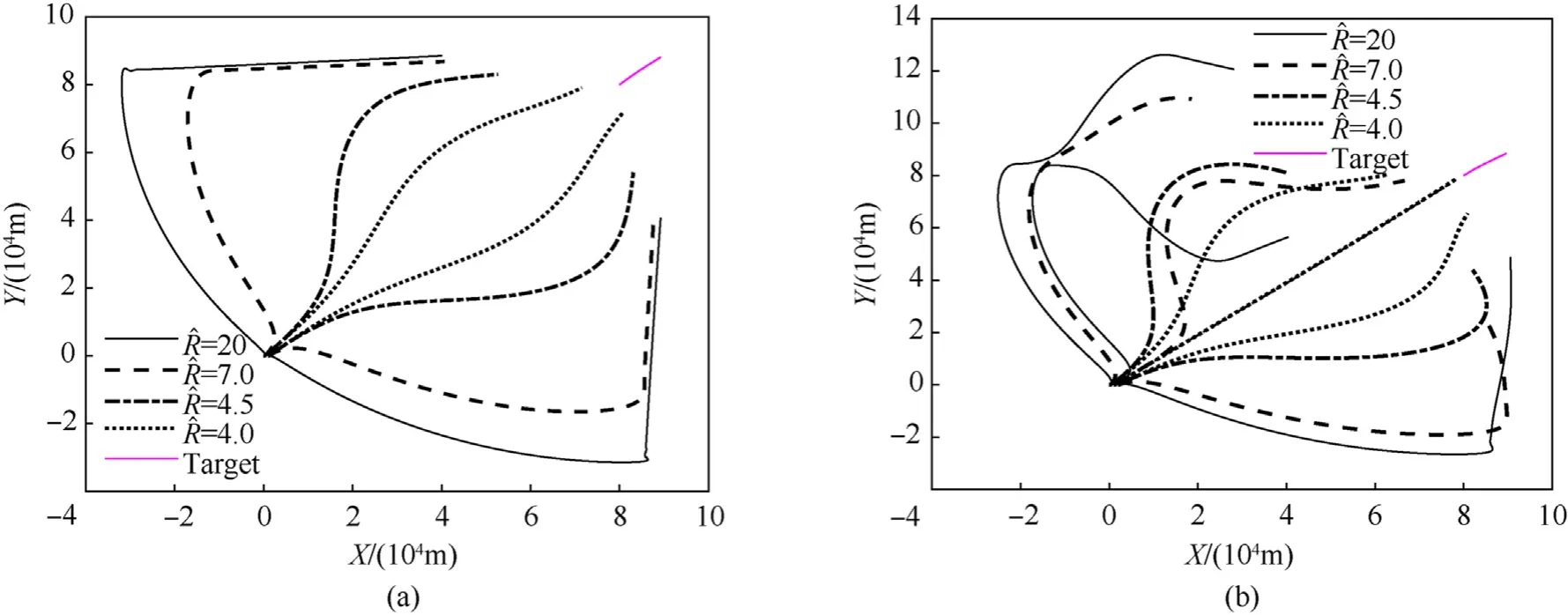
Fig.14. RHO method: Cooperative tracking trajectories with different relative range ^R: (a) Cooperative tracking trajectories by two UAVs; (b) Cooperative tracking trajectories by three UAVs.

Fig.15. Feedback guidance method: Cooperative tracking trajectories with different proportional coefficient ki: (a) Cooperative tracking trajectories by two UAVs; (b) Cooperative tracking trajectories by three UAVs.
5.2. Comparative experiment of the feedback guidance method and the LGVF algorithm
Simulation experiments are carried out in this section to test the impact of the trajectories optimized by the feedback guidance method on the target-location estimation. The simulation conditions of the feedback guidance are the same as Section 5.2. First,multi-UAV trajectories are planned by the LGVF method.Then,the target states estimated by the two methods are compared to verify the effectiveness of the proposed feedback guidance method.
Lyapunov vector field guidance is defined as
whereris the position of the target that can be estimated from the filter,andR0is a desired standoff distance from the UAV to the target.vdis a desired UAV speed. In this simulation setR0=20 km and vd= 110 m/s.
To obtain the expected heading angle of the UAV through vector field guidance
A proportional controller is designed using the principle of feedback control
Phase-angle keeping is separately accomplished by controlling the speed of the UAVs.
When two UAVs are assigned to track a target, the speed commands of two UAVs are expressed as [21].
When three UAVs are assigned to track a target, the speed commands of the three UAVs are given by[27].
Using the feedback guidance law of Eq. (18) and LGVF method for the cooperative tracking target of two UAVs, Fig. 16 show the variation in the RMSE of position and velocity in 200 trials and. It can be seen that the feedback guidance method can significantly enhance the target tracking accuracy compared with the LGVF method. Table 3 shows that the proposed algorithm effectively improves position and velocity tracking accuracy by 52.2% and 14.3%,respectively(comprising theXandYdirections).

Table 3RMSE comparison result of two UAVs.
Simulation results of RMSE are displayed in Fig.17.Fig.17 shows that since the proposed method can effectively plan the observation position, the tracking error can be effectively reduced compared with LGVF in approach target stage. The comparison of the parameters in Table 4 also confirms this conclusion.

Table 4RMSE comparison result of three UAVs.
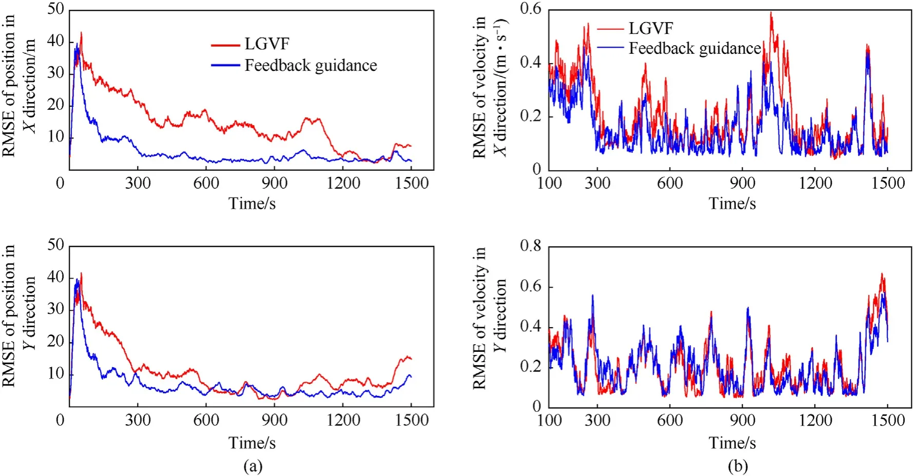
Fig.17. The RMSE of target state estimation of three UAVs: (a) The RMSE of position; (b) The RMSE of velocity.
The estimate state displayed in Fig.18 show that the proposed method of four UAVs can effectively improve the accuracy. The comparison of the parameters in Table 5 shows that the proposed algorithm effectively improves position and velocity tracking accuracy by 55.2% and 14.7%, respectively (comprising theXandYdirections).

Table 5RMSE comparison result of multi-UAVs.
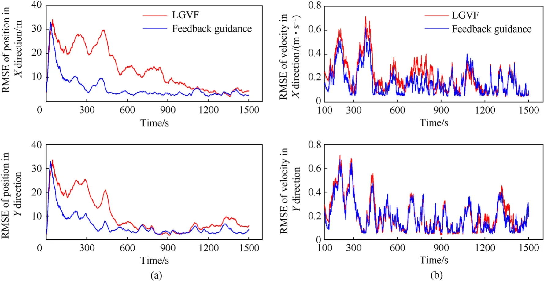
Fig.18. The RMSE of target state estimation of multi-UAVs: (a) The RMSE of position; (b) The RMSE of velocity.
In summary, the proposed feedback guidance method can effectively optimize the trajectory of UAVs and improve the precision of cooperative target tracking.The simulation results verify the effectiveness of the proposed method.
5.3. Cooperative tracking maneuvering target
This section discusses the effectiveness of the proposed feedback guidance method in tracking maneuvering target. The maneuvering speed of target is 20 m/s, and the target performs maneuvering with an acceleration of -0˙075 m/s2in the vertical direction and 0˙075 m/s2in the horizontal direction for the 200—550 s. The acceleration of 0˙15 m/s2in the vertical direction and-0˙15 m/s2in the horizontal direction for the 550—1000 s,and the uniform movement is maintained for the remainder of the time.The acceleration variance σ2a=0˙66 m/s2andα = 0˙9, the rest of the parameters are the same as subsection 5.1.
The simulation results are shown in Fig. 18. The resulting trajectories are shown in Fig. 19(a), and the line-of-sight angle between the UAVs and the target is shown in Fig.19(b).By Fig.19(a),the optimal observation configuration is formed while approaching the target,which is beneficial for observation.Fig.19(b)shows the geometric configuration of the UAV,and the target is maintained at 90◦.Fig.19(c)shows the target maneuvering trajectory.In Fig.19(c),the estimated state of the target is basically consistent with the real state, and the error is very small. Therefore, the proposed method can better track the maneuvering target.

Fig. 19. Cooperative tracking maneuvering target of two UAVs: (a) Cooperative tracking trajectories; (b) The line-of-sight angle between UAVs and target; (c) The estimated and real track of the maneuvering target.
The simulation results of three UAVs and four UAVs are shown in Fig. 20 and Fig. 21, respectively. From Fig. 20 and Fig. 21, the proposed trajectory optimization algorithm of three UAVs and four UAVs can guidance the UAV approach the target and form the optimal observation configuration.
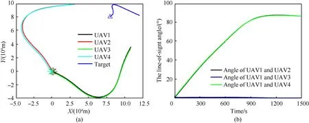
Fig. 21. Cooperative tracking maneuvering target of multi-UAVs: (a) Cooperative tracking trajectories; (b) The line-of-sight angle between UAVs and target.
In Fig. 22, the RMSE of position and RMSE of velocity are displayed. From Fig. 22(a), the RMSE of the target position is decreasing as the number of UAV increases, which indicates that increasing the UAV number can improve the accuracy of target position estimation. In Fig. 22(b), the error of target velocity estimation becomes larger from 550 to 1000 s. The reason is that the motion state of the target changes from uniform motion to accelerated motion.
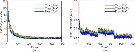
Fig. 22. The RMSE of the maneuvering target: (a) The evolution of position RMSE; (b) The evolution of velocity RMSE.
6. Conclusions
This paper proposes the feedback guidance method to solve the trajectory optimization problem for multi-UAVs target tracking in approaching stage. The feedback guidance method has strong stability and good real-time performance. Additionally, the proportional coefficient of the feedback guidance law can be adjusted to adapt to the optimal trajectory with different UAV observation accuracies. From the numerical results, we can draw the following conclusions:
(1) For UAVs equipped with high range accuracy and low angle accuracy sensors, the optimal trajectory tends to perform triangulation first and then move toward the target for multi-UAVs cooperative target tracking.
(2) The global stability of the feedback guidance method can stabilize the UAV in the optimal observation configuration.
(3) The proposed feedback guidance method can improve tracking accuracy and is superior for target tracking compared with the RHO and the LVFG methods.
In fact, since the feedback guidance algorithm is not designed for the case of noise uncertainty, the robustness of the proposed algorithm is not better than the RHO algorithm. Moreover, the proportion coefficient in the algorithm has not been adjusted adaptively, and the adaptability of the algorithm is not good.Improving the robustness and adaptability of the algorithm is our next effort. Another future research will focus on extending this method to three-dimensional space and tracking multiple targets.
Declaration of competing interest
The authors declare that they have no known competing financial interests or personal relationships that could have appeared to influence the work reported in this paper.
Acknowledgements
The authors would like to express their acknowledgement for the support from the National Natural Science Foundation of China(No.61773395).
Appendix A
This appendix is a proof of Theorem 2.
Proof. Consider the following Lyapunov function
When δ12=π/2,V= 0. Note that
From Eq. (21), one obtains
Submitting this into Eq. (A1) gives
LetA=we have
WhenA>0 0
WhenA<0, -and thenIn summation,f1<0. Similarly, it can be proven thatf2<0.Therefore,for ∀δ12≠π/2, ˙V<0. This completes the proof.
Appendix B
This appendix is a proof of Theorem 4.
Proof.Consider the following Lyapunov function
When δ12= π/3, δ13= 2π/3,V= 0. Note that ∀δ12≠π/3,δ13≠2π/3,V>0.
Submitting Eq. (A2) into Eq. (B1) gives
DefineA=thenand we have:
In summation,f1 ≤0. Similarly, it can be proven thatf2< 0,f3<0.
Therefore, for ∀δ12≠π/3, δ13≠2π/3, ˙V<0.Thus, the proof is completed.
Appendix C
Proof.Consider the following Lyapunov function
This appendix is a proof of Theorem 6.
When δ12= δ14= δ32= π/2,δ13= 0,V= 0. Note that δ12=δ14=δ32≠π/2,δ13≠0,V>0.
Submitting Eq. (A2) into Eq. (C1) gives
DefineAand submitting Eq. (C3) into Eq. (C2) gives
In summation,f1 ≤0.Similarly,it can be proven thatf2< 0f3<0f4<0,f5<0.Therefore, for δ12= δ14= δ32≠π/2,δ13≠0, ˙V< 0.Thus,the proof is completed.
[1] Lyu Y,Kang TN,Pan Q.UAV sense and avoidance:concepts,technologies,and systems. Sci Sin Inform 2019;49(5):520—37.
[2] Choe R, Puig-Navarro J, Cichella V, Xargay E, Hovakimyan N. Cooperative trajectory generation using pythagorean hodograph b′ezier curves. J Guid Control Dynam 2016;39(8):1—20.
[3] Lee D, Kim S, Suk J. Formation flight of unmanned aerial vehicles using track guidance. Aero Sci Technol 2018;76:412—20.
[4] Fonod F,Shima T.Estimation enhancement by cooperatively imposing relative intercept angles. J Guid Control Dynam 2017;40(7):1711—25.
[5] He SM, Shin HS, Tsourdos A. Trajectory Optimization for multitarget tracking using joint probabilistic data association filter[J]. J Guid Control Dynam 2020;43(1):170—8.
[6] Oshman Y,Davidson P.Optimization of observer trajectories for bearings-only target localization. IEEE Trans Aero Electron Syst 1999;35(3):892—902.
[7] Ponda SS, Kolacinski RM, Frazzoli E. Trajectory optimization for target localization using small unmanned aerial vehicles. In: 2009 AIAA guidance,navigation, and control conference; 2009. p. 1—25.
[8] Grocholsky B, Makarenko A, Durrantwhyte HF. Information-theoretic coordinated control of multiple sensor platforms.In:Proceeding of the 2003 IEEE;2003. p. 1521—6.
[9] Xu S, Dogancay K. Ptimal sensor placement for 3-d angle-of-arrival target localization. IEEE Trans Aero Electron Syst 2017;53(3):1196—211.
[10] Zhang S,Guo Y,Lu Z.Cooperative detection based on the adaptive interacting multiple model-information filtering algorithm. Aero Sci Technol 2019;93:105310.
[11] Hu C, Zhang Z, Tao Y. Decentralized real-time estimation and tracking for unknown ground moving target using UAVs. IEEE Access 2019;7:1808—17.
[12] Wang YX, Zhang T, Ca ZH. Multi-UAV coordination control by chaotic grey wolf optimization based distributed MPC with event-triggered strategy.Chin J Aeronaut 2020;33(11):2877—97.
[13] Wang DZ, Huang DQ, Xu C. A closed-form method for simultaneous target localization and UAV trajectory optimization. Appl Sci 2021;11(1):114.
[14] Zhang Z, Li J, Wang J. Sequential convex programming for nonlinear optimal control problems in UAV path planning. Aero Sci Technol 2018;76:280—90.
[15] Uluskan S. Noncausal trajectory optimization for real-time range-only target localization by multiple UAVs. Aero Sci Technol 2020;99:105558.
[16] Cui NG, Guo DZ, Li KY, Wei CZ. A survey of numerical methods for aircraft trajectory optimization. Tactical Missile Technol 2020;5:37—51.
[17] Ousingsawat J, Campbell ME. Optimal cooperative reconnaissance using multiple vehicles. J Guid Control Dynam 2007;30(1):122—32.
[18] Kim S, Oh H, Tsourdos A. Nonlinear model predictive coordinated standoff tracking of a moving ground vehicle. J Guid Control Dynam 2013;36(2):557—66.
[19] Zhu Q, Zhou R, Dong ZN,Li H. Coordinated standoff target tracking using two UAVs with only bearing measurement. J Beijing Univ Aeronaut Astronaut 2015;41(11):2116—23.
[20] Roh H, Cho MH, Tahk MJ. Trajectory optimization using Cram′er-Rao lower bound for bearings-only target tracking. AIAA Guid Navig Contr Conf 2018:1—10.
[21] Frew EW, Lawrence DA, Morris S. Coordinated standoff tracking of moving targets using Lyapunov guidance vector fields. J Guid Control Dynam 2008;31(2):290—306.
[22] Lawrence DA, Frew EW, Pisano W. Lyapunov vector fields for autonomous UAV flight control. J Guid Control Dynam 2008;31(5):1220—9.
[23] Lim S, Kim Y, Lee D. Standoff target tracking using a vector field for multiple unmanned aircrafts. J Intell Rob Syst 2013;69(1—4):347—60.
[24] Jung W, Lim S, Lee D. Unmanned aircraft vector field path following with arrival angle control. J Intell Rob Syst 2016;84(1—4):311—25.
[25] Zhao SY,Chen BM,Tong HL.Optimal deployment of mobile sensors for target tracking in 2D and 3D spaces. IEEE CA J Auto Sinica 2015;1(1):24—30.
[26] Song ZQ, Li HX, Chen CL. Coordinated standoff tracking of moving targets using differential geometry. J Zhejiang Univ - Sci C 2014;15(4):284—92.
[27] Yao P,Wang HL,Su ZK.Cooperative path planning with applications to target tracking and obstacle avoidance for multi-UAVs. Aero Sci Technol 2016;54:10—22.
[28] Kokolakis N, Koussoulas NT. Robust standoff target tracking with finite-time phase separation under unknown wind. J Guid Control Dynam 2021;44(6).https://doi.org/10.2514/1.G005517. in press.
[29] Sinclair AJ, Prazenica RJ, Jeffcoat DE. Optimal and feedback path planning for cooperative attack. J Guid Control Dynam 2008;31(6):1708—15.
[30] Zhao SY, Li Z, Ding Z. Bearing-only formation tracking control of multi-agent systems. IEEE Trans Automat Control 2019;64(11):4541—54.
[31] Wang L. Modeling and optimization for multi-UAVs cooperative target tracking. Changsha, China: National University of Defense Technology; 2011.
[32] Zhao SY, Chen BM, Tong HL. Optimal sensor placement for target localization and tracking in 2D and 3D. Int J Control 2013;86(10):1687—704.
Hao-ran SHI was born in 1992, his research interests include fields of systems and control, optimization theory and target localization and tracking by UAVs.
Fa-xing LU was born in 1974, His research interests include fields of command and control.
Ling WU was born in 1976, His research interests include fields of command and control.
杂志排行
Defence Technology的其它文章
- A review on lightweight materials for defence applications: Present and future developments
- Study on the prediction and inverse prediction of detonation properties based on deep learning
- Research of detonation products of RDX/Al from the perspective of composition
- Anti-sintering behavior and combustion process of aluminum nano particles coated with PTFE: A molecular dynamics study
- Microstructural image based convolutional neural networks for efficient prediction of full-field stress maps in short fiber polymer composites
- Modeling the blast load induced by a close-in explosion considering cylindrical charge parameters
