External blast flow field evolution and response mechanism of singlelayer reticulated dome structure
2023-07-04ShoboQiGungynHungXudongZhiFengFn
Sho-bo Qi , Gung-yn Hung ,d,*, Xu-dong Zhi , Feng Fn
a State Key Laboratory of Explosion Science and Technology, Beijing Institute of Technology, Beijing,100081, PR China
b Key Lab of Structure Dynamic Behaviour and Control of the Ministry of Education, Harbin Institute of Technology, Harbin,150090, China
c Key Lab of Smart Prevention and Mitigation of Civil Engineering Disasters of Ministry of Industry and Information Technology, Harbin Institute of Technology, Harbin,150090, China
d Beijing Institute of Technology Chongqing Innovation Center, Chongqing, 401120, China
Keywords:External blast loading Reticulated dome structure Fluid-structure interaction Dynamic response mode Response mechanism
ABSTRACT
1. Introduction
Statistics of global terrorism database(GTD)reveals that nearly 200,000 incidents of terrorist bombing have taken place in 1970—2019 [1], and in recent times there are on average 2000 incidents per year (i.e.,more than five per day)[2].Considering that the public buildings have considerable social influence as they serve to accommodate large population and valuable equipment in high profile events,they are attractive targets in the current era of increasingly frequent terrorist attacks. Terrorist attacks can cause massive property damage and casualties especially for public buildings,e.g.,the collapse of World Trade Center in 2001 not only caused more than $200 billion in property damage but also killed nearly 3000 people on the ground in New York. So, it has great significant to understand the dynamic response performance on such public buildings and minimize the losses induced by explosion.
Large span space structures [3] are widely used for public buildings such as stadiums, airport terminals, aircraft hangars,exhibition centers, cinemas, etc. Among large span space structures, single-layer reticulated dome structures (SRDS) are frequently adopted as their roof, because the curved surface is not only aesthetically appealing but also provides outstanding mechanical characteristics. Prominent examples of SRDS include the National Center for the Performing Arts in China (212 m long span×140 m short span),the Nagoya Dome in Japan(187 m span),etc. The SRDS that experienced bombing incidents in the last decade include the Turkish Vodafone stadium (2016), the Manchester arena (2017), etc. If the structure collapses, it will bring secondary damage on members of the public. It is indeed of considerable social and economic significance to assess the explosion resistance of SRDS to improve their safety and thus protect the public.
In evaluating the explosion resistance of structures, design manuals(e.g.,TM5-855-1[4],TM5-1300[5],UFC3-340-01[6],and UFC3-340-02 [7]) generally use the equivalent static load and the system's equivalent single degree of freedom to quantify how well can the components and connectors of building structures resist explosive impact. However, SRDS cannot be simplified as systems with a single or multiple degree of freedom because threedimensional collaborative forces are pivotal, and this situation precludes the otherwise viable standard analysis [4—7]. Consequently, finite element simulation and field test methods are needed to study the complex structural response of SRDS under external blast load.
The powerful arbitrary Lagrangian—Eulerian (ALE) finite element method may fall short on computational efficiency in evaluating the SRDS because numerous air grids must be established in the model to simulate the explosion generation and the coupling process of SRDS.In fact,according to Yang[8]and Sun[9],ALE is inferior in analyzing the blast resistance of SRDS in comparison with the pure Lagrangian algorithm (based on ConWep)[10], the multi-material arbitrary Lagrange—Eulerian algorithm[11,12], the coupling empirical loading and ALE algorithm [13,14],the particle blast Lagrangian—Eulerian algorithm [15—17], etc. Sun[9]pointed out based on the pure Lagrangian algorithm that there are four response modes for SRDS under external blast loading,i.e.,no damage,local depression,local failure,and overall collapse.Zhi and Stewart [18] considered the influence of rise-span ratio, roof load, structural span, and other parameters on the structural response laws of SRDS to define four damage levels, namely no damage, mild damage, severe damage, and progressive collapse.Nevertheless,experimental validation of these pure Lagrangian and Lagrangian—Euler numerical methods on this topic has not been reported in literature, presumably because such efforts in a laboratory setting necessitates creating the appropriate blast field that can be of considerable safety risk and financial burden, and the accuracy of their modeling results remains questionable. To make things worse, the conclusions on the SRDS from the ConWep code has poor credibility because when it comes to dome structures,ConWep overestimates the impulse and positive duration on the front hemisphere and underestimates the peak-reflected overpressures [19—21]. To describe a real scene of terrorist explosion,the authors previously carried out some exploring researches on gas explosion tests [22] and conventional weapon explosion response test [23] on the small scaled kiewitt-6 single-layer spherical reticulated dome structure,and found a variety of failure modes.
The above analysis is limited to the discussion of numerical methods and response modes of SRDS subject to explosion, and these research achievements are still inadequate to be used to lay down the design code and guide design of engineering at present,as the response mechanism is still empty in this topic. The motivation behind this study was to validate the numerical methods in studying elastic and inelastic dynamic responses by field experiments and then investigate the dynamic response modes of an actual-scale single-layer reticulated dome structure.In the present work, the previous field explosion experiments of small size SRDS[23] are used to validate the numerical models and establish a reliable analysis method on the external blast wave propagation and structural failure mechanism of SRDS.Then parametric analysis is further done to reveal the dynamic response and energy consumption rules of SRDS under explosion and thus elucidate the response modes and failure mechanism.
2. Finite element modelling and verification
2.1. Brief introduction of the field explosion test
In our previous work [23], the blast performance and the residual axial capacity of SRDS specimens under explosion was studied by conducting field tests, which are briefly introduced as follows.
Two SRDS built with Q235 steel were tested both numerically and experimentally (Fig.1), and each had four major components,i.e., rigid support, steel plate (0.5 mm thick), steel structural members(made of steel tubing of 1 mm thickness and 6 mm outer diameter), and structure joints (5 kg). The span of the SRDS is 1800 mm,and the rise-span is 1/3.The explosive charge(TNT,1 kg in test case 1, 3.145 kg in test case 2) was detonated at a standoff distance of 2 m from the SRDS on the ground. An overpressure measuring system facing the explosion source was installed at 2.2 m away from the initiation point to measure the blast shock wave intensity in each test case.PCB 113B24 piezoelectric pressure sensor whose sensitivity coefficient is 0.725 mV/kPa and maximum range is 6700 kPa, was used to obtain overpressure—time history.The high-speed camera was used to record the dynamic response process of the structure. In addition, the sampling rate of the TST5910 used for recording the overpressure data, was set to 100 kHz per channel.
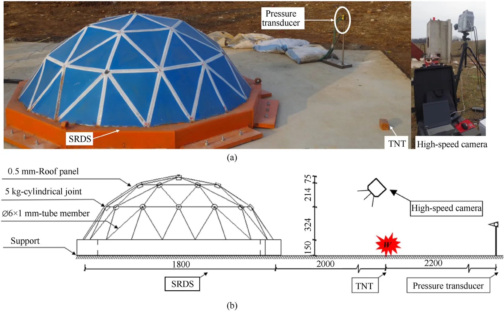
Fig.1. Explosion field test on SRDS [23]: (a) Explosion field test; (b) Sketch of explosion test scenarios (unit: mm).
2.2. Finite element modeling and mesh convergence analysis
The commercial hydro-code ANSYS/LS-DYNA, which can simulate extreme deformation problems,was employed to evaluate the dynamic behaviors of SRDS under explosion (Fig. 2).
In the model,SRDS consists of Hughes—Liu beam elements.The additional weight joints on the SRDS are represented by a lumped mass element assigned to the corresponding nodal point. The Belytschko—Tsay shell element is utilized to model the ground,support, and roof panel. For the boundary condition, nodes of all the members and panels along the support edges were assumed as fully constrained. The joints are simplified as mass elements for precision and reduced calculations. The Lagrangian formulation is applied for the reticulated dome structure and the ground.
The Cowper—Symonds model is adopted for studying the dynamic mechanical behavior of mild steel at various strain rates:
The fluid-structure interaction method considers the interaction between the structure and the blast wave that propagates in air.The air domain that surrounds the structure and the explosive is modeled in a cuboid Eulerian region with a size of 4400 × 1000 × 2200 mm3. A flow-out boundary condition is applied at the top and the side of the Eulerian domain. The solid element is adopted for air and TNT, and it is specified the initial conditions(charge initial position,shape,initiation point)[25—27].The arbitrary Lagrangian—Eulerian(ALE)formulation is applied for simulating TNT and air as multi-material fluids.The NULL material model is adopted for air, which is assumed as an ideal gas in the present study, and the LINEAR_POLYNOMIAL equation of state in LS-DYNA is used [28].
whereVandE0are the internal volume and energy,andC0—C6are the equation of state parameters and the material properties of air(Table 1).

Table 1Parameters of the air [25].
The HIGH_EXPLOSIVE_BURN model is employed to describe TNT with the JWL equation of state [25].
whereA,B,R1,andR2are constants,ω is the reported specific heat,Vis the relative volume, andEis the internal energy per initial volume. Table 2 lists the material properties of TNT[28].

Table 2Parameters of the TNT [28].
To balance the computing efficiency and reliability, a mesh convergence analysis is firstly carried out.The element sizes of theEulerian region in the LSDYNA numerical model are set to 0.025 m,0.03 m, 0.04 m and 0.05 m, respectively. The Lagrangian element and the Eulerian element has approximately the same size for the fluid-structure interaction calculation to be free of shockwave leakage through the roof panel. Fig. 3 shows the ratio of the experimental and numerical reflected overpressure at reference locations under different mesh size,which indicates that the mesh density has a certain effect on blast load.With the decrease of the grid size, ratio of the experimental and numerical reflected overpressure is closer to 1 and tends to stable,especially when the grid size is less than 0.03 mm.Further,it can be seen from Fig.4 that the numerical and the experimental reflected overpressure and impulse history have the same trend in general and are in good agreement, and the relative error is less than 10% for both the overpressure(Pr)and the impulse(Ir).Considering the accuracy and computational cost,a 3D Eulerian element size of 0.03 m is selected in following numerical model.
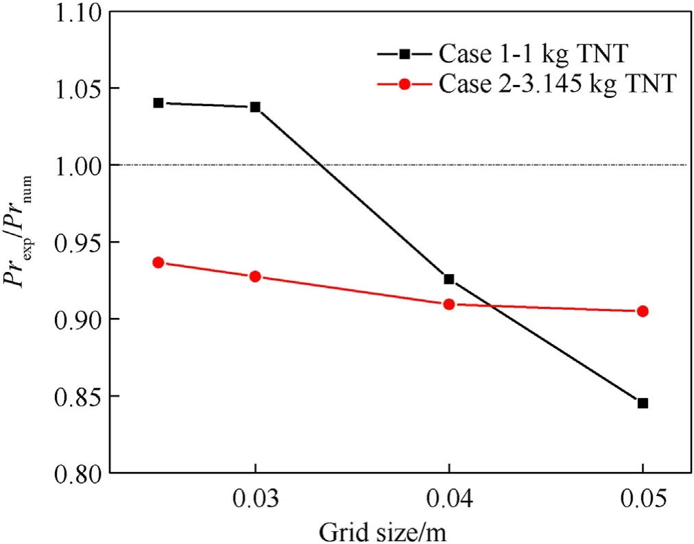
Fig. 3. Comparison of the peak-reflected pressure for different grid sizes.
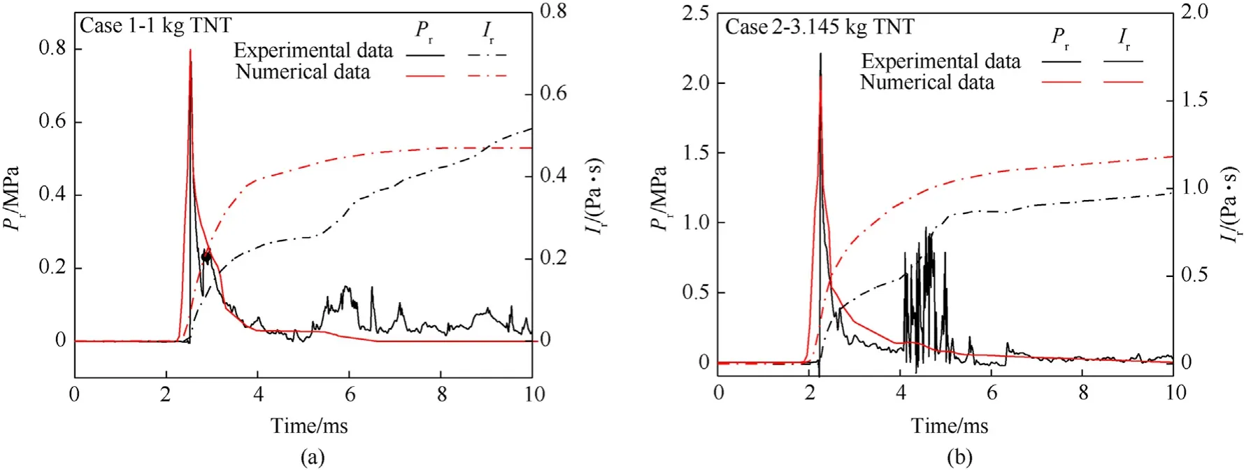
Fig. 4. Overpressure and impulse time history curves at reference locations: (a) Case 1; (b) Case 2.
2.3. Explosion flow field and structural response verification
The fluid-structure interaction model in ANSYS/LS-DYNA is used to simulate the generation and propagation progress of blast wave,the reflection of the blast wave on the structure, and the deformation process of the structure[29].Fig. 5 and Fig.6 illustrate the dynamic response of the dome structure in test case 1 and test case 2 in the numerical simulation and in the explosion experiment,respectively.
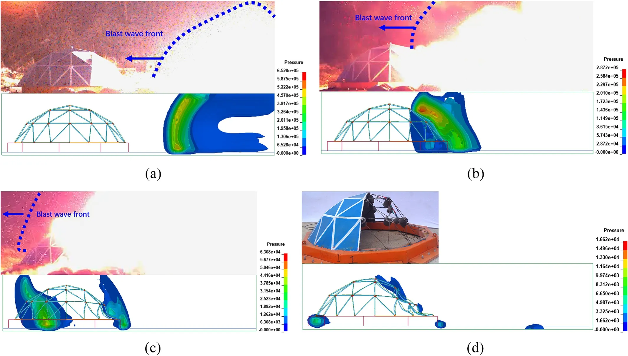
Fig. 5. Fluid-structure interaction process in case 1: (a) 1 ms; (b) 3 ms; (c) 6 ms; (d) 30 ms.
It can be seen from the images of 1 ms that the detonation system initiates the explosion, which generates detonation products along with a hemispherical blast wave.At 3 ms after initiation,the blast wave reaches the dome structure and reflects on the front side, but there is no obvious deformation. When the blast wave continues to propagate along the structure and climbs over the top to the rear dome surface, the front dome surface starts to demonstrate inward concave deformation. The blast wave arrives at the rear surface of the dome structure faster in test case 2(at 5 ms)than in test case 1 (at 6 ms), because the former has a higher TNT equivalent. The blast wave then continues to flow around the rear and spread, and the deformation response of the structure continues to escalate after the explosive loading has been completed.For test case 1, the deformation on the blast front that faces the surface of the structure reaches the maximum at 30 ms(Fig.5(d)),and then gradually stabilizes in the new equilibrium position after vibrations at a small amplitude. The bottom area of the panel fractured, from which the explosion shock waves flow into the interior of the structure.Owing to the intensified blast loading,the roof panel in the front undergoes plastic deformation; this panel was removed to study the characteristics of the bending failure occurring in the tube members. The tube members located in the second and third latitudinal circles show in-plane bending and residual compressive deformation. For test case 2, the structure arrives at maximum deformation at 20 ms, at which point almost all joints located at the front dome touch the ground (Fig. 6(d));eventually the SRDS collapses because the bearing capacity is completely lost.All of the roof panels undergo plastic deformation,and the phenomena of tearing failure and dispersion of panel fragments are observed. In addition, all the tube members suffer severe bending deformation along with fractures and failures in the region located towards the explosive.
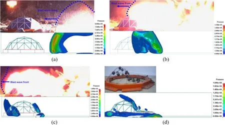
Fig. 6. Fluid-structure interaction process in case 2: (a) 1 ms; (b) 3 ms; (c) 5 ms; (d) 20 ms.
Explosion flow field analysis proves that large structural deformation appears after the explosive loading, so the influence of structural response on the blast wave propagation is limited. In addition, the numerical analysis is in good agreement with the experimental results, so it is further used to study the dynamic response of SRDS under external explosion.
3. Response modes and mechanism of SRDS
3.1. Parametric analysis program
Based on the verified numerical simulation method and material constitutive model,an explosion scenario considered in Fig.7 is a terrorist explosive with an TNT weight ofWplacedRaway from the target structure.A Kiewitt-8 single-layer reticulated dome with 6 rounds, span ofL, rise-height ofFand supporting heightHis establish as typical structure. Fig. 7 presents a parametric analysis of the reticulated dome members (including radial member, latitudinal member, diagonal member), purlin hanger, purlin, rivet,and roof panel in a refined model. Table 3 lists the variables of structural parameters and the explosion parameters involved in Fig. 7. For the convenience of subsequent discussion, some interesting members (FB1-FB3, RB5-RB7) and nodes (FN1-FN4, TN4,RN1-RN4)on the reticulated dome structure are numbered,and the top view of whose distributions are shown in Fig. 7(c). To investigate the deformation degree of the member from the micro level,there are four integration points in the cross-sections of tube members and the symbolnP indicates that there are at least n integration points in cross section of reticulated dome tube member undergoing plasticity.So 1 P indicates that there is at least one integration point that yielded, and 4 P shows that the entire section enters into plastic deformation.

Table 3Calculation parameters of SRDS under explosion.
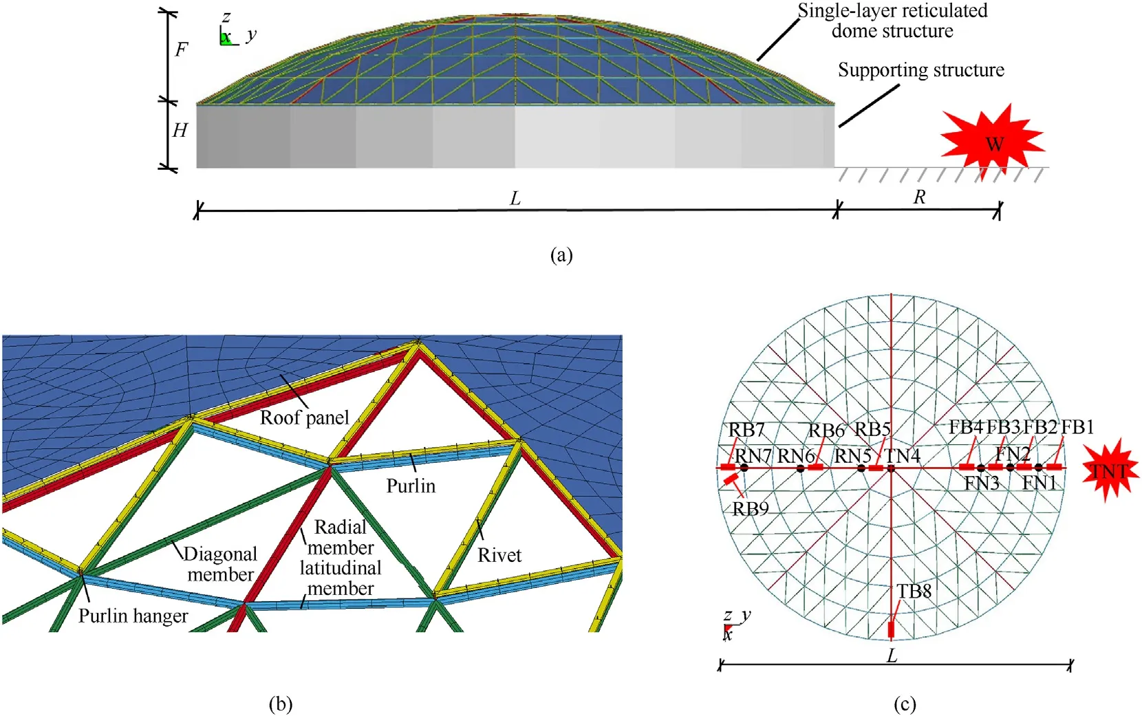
Fig. 7. Finite element calculation model of Kiewitt 8 single-layer spherical reticulated shell: (a) Elevation of single-layer reticulated dome under explosion; (b) Local schematic diagram of FE model; (c) Top view of joints and members.
3.2. Deformation modes
3.2.1. Minor vibration
The SRDS shows a typical small amplitude vibration as the stress response (Fig. 8) when the explosion has the following settings:span, 60 m;supporting height,5 m; rise/span ratio,1/7; weight of TNT,1000 kg;detonation distance,32 m,roof load,120 kg/m2(set of condition referred to as L60H5F7W1000R32P120). The initial equilibrium state is broken at 5 s and the structure then starts to vibrate, as can be seen from a rapid growth of stress that quickly reaches the maximum after loading. At about 5.5 s, all members and nodes begin to vibrate freely in small amplitudes near the new equilibrium state.Most members are still in an elastic state,which can be observed microscopically and is also evident in the stresstime history (Fig. 8(e)). The plasticity remains low as the plastic development proportion of the 1 P and 4 P members is 10.5% and 1.8% respectively, and the average plastic strain of the members is 7.02×10⁻⁵.As for residual deformation performance(Fig.9),there is a slight displacement response in the first and the second ring,and the overall maximum displacement deformation is 0.163 m,which is 1/368 of the span.According to the above analysis,during minor vibration,the whole structure is basically in an elastic state,and there is no significant change in the overall stiffness.
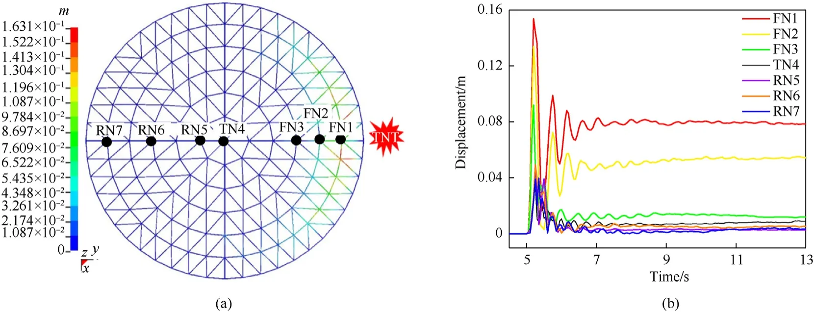
Fig. 9. The displacement deformation in minor vibration: (a) Contour of deformation; (b) Displacement histories of major joints.
3.2.2. Local depression
The SRDS shows a typical local depression as the stress response(Fig.10)when the explosion has the following settings:span,60 m;supporting height,5 m;rise/span ratio,1/5;weight of TNT,1500 kg;detonation distance, 20 m, roof load, 180 kg/m2(set of condition referred to as L60H5F5W1500R20P180). According to the stresstime history of FB1 and FB2, the front members reach the yield state rapidly after blasting, which causes considerable displacement deformation in the two lower rings facing the explosion.In addition,the obvious deformation in FN3(Fig.11)causes some geometric displacement in third and the fourth ring members near FN3 and contributes to the overall deformation.After 5.5 s,the structure begins to vibrate freely near the equilibrium to gradually stabilize. During the local depression, the 1 P is 34.4%, the 4 P is 13.2%,and the average plastic strain of members is 1.13×10⁻³.The residual displacement response (Fig. 11) has a maximum displacement of 2.245 m, which is 1/26.7 of the span, and a top displacement of 0.15 m, which is 1/400 of the span. The above analysis shows that during local depression, the outermost ring members closest to the explosion enter a deep buckling state,which causes significant geometric deformation. The whole structure still manages to maintain its initial geometry although the local stiffness is weakened.
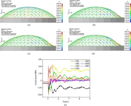
Fig.10. The deformation process of local depression: (a) 5 s; (b) 5.5 s; (c) 6 s; (d) 13 s; (e) Axial stress of members.
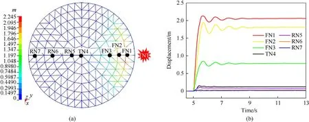
Fig.11. The displacement deformation in local depression: (a) Contour of deformation;(b) Displacement histories of major joints.
3.2.3. Severe damage
The SRDS shows a typical severe damage as the stress response(Fig.12)when the explosion has the following settings:span,40 m;supporting height,5 m;rise/span ratio,1/5;weight of TNT,3000 kg;detonation distance, 15 m, roof load, 120 kg/m2(set of condition referred to as L40H5F5W3000R15P120). In this case, the blast loading is so large that all members abruptly experience large tensile stress until 5.1 s.The stress of each member vibrates in large amplitudes (Fig.12) and the displacement of each node increases continuously (Fig. 13) before 6.5 s, until stress redistribution is accomplished for the stress and displacement to undergo stable vibration.Most members,especially the outermost first and second rings, enter the plastic state, which causes serious buckling deformation. The 1 P and 4 P is 83.6% and 52.7% respectively, and the average plastic strain of members is 8.38 × 10⁻³. In the residual displacement deformation cloud (Fig. 13), the maximum deformation occurs in the third ring facing the explosion, and the top and rear of the structure also have severe displacement. The maximum displacement is 7.799 m,which is 1/5.13 of the span,and the top displacement is 3.82 m,which is 1/10.5 of the span.During severe damage, most parts of the structure undergo large-scale buckling deformation and lose their initial shape. The overall stiffness is greatly weakened in a deep elastic-plastic stage as the normal of the structure geometry reverses in local regions.
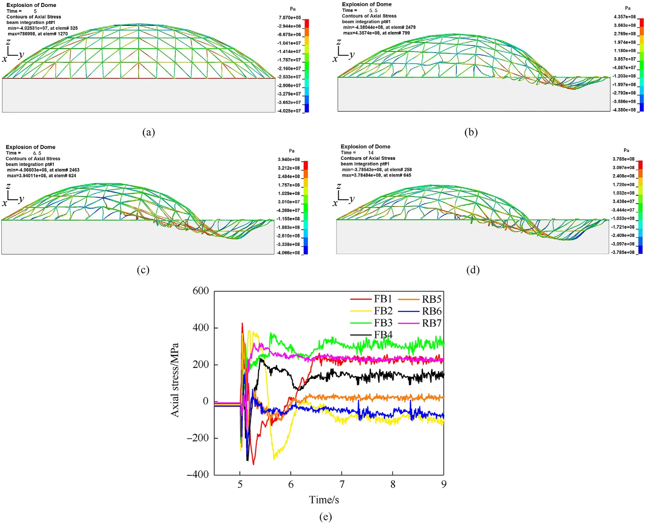
Fig.12. The deformation process of severe damage: (a) 5 s; (b) 5.5 s; (c) 6.5 s; (d) 14 s; (e) Axial stress of members.
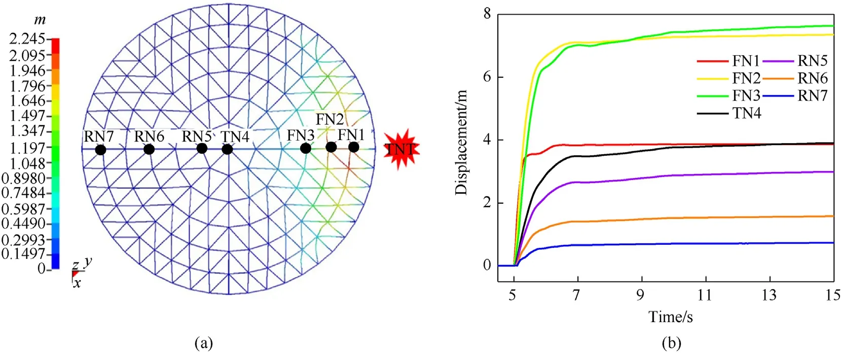
Fig.13. The displacement deformation in severe damage: (a) Contour of deformation; (b) Displacement histories of major joints.
3.2.4. Overall collapse
The SRDS shows an overall collapse as the stress response(Fig.14)when the explosion has the following settings: span, 40 m; supporting height, 5 m; rise/span ratio, 1/7; weight of TNT, 2500 kg;detonation distance, 15 m, roof load, 180 kg/m2(set of condition referred to as L40H5F7W2500R15P180).Because the blast loading is so large, the initial self-equilibrium stress state is broken around 5.1 s. At this point, the FB1 member on the first ring receives the explosion energy and quickly enters the yield stage for the front of the SRDS to start deep buckling at 5.5 s.Inward concave deformation begins from the outermost rings and then expands to the inner rings,and the members continue to buckle and maintain a relatively high stress level. Because the structure does not have enough plastic resistance against the received explosion energy, the excess explosion energy causes larger geometric displacement of the structure.Therefore,at 8 s,the top of the reticulated shell sinks to the height of the bottom supporting structure, and then the structure exhibits reverse deformation.Because the outermost ring members are under high tensile stress, the FN1 measuring point on the first ring is at a maximum deformation level before 9 s(Fig.15).With the explosion energy mostly consumed by the severe geometric deformation and plastic deformation of the front members,the rear members enter an elastic stage before 9 s (e.g., RB5-7 in Fig.14) with relatively small displacement(e.g.,RN5-7 in Fig.15).With further large deformation after 9 s,all members experience high tension and stabilize after 11 s.The 1 P and 4 P is 93.9% and 77.4% respectively, and the average plastic strain of members is 1.19 × 10⁻². The residual displacement deformation cloud(Fig.15)reveals that the deformation in each ring is relatively uniform, and the deformation amplitude from the outermost ring to the innermost ring increases continuously. The maximum geometric deformation, which is 19.22 m and 1/2.08 of the span, occurs at the structural vertex. In the overall collapse, the whole structure completely loses its initial geometric configuration,as the normal direction of the shape is reversed in the new equilibrium.The overall stiffness is lost completely during a deep plastic development stage.
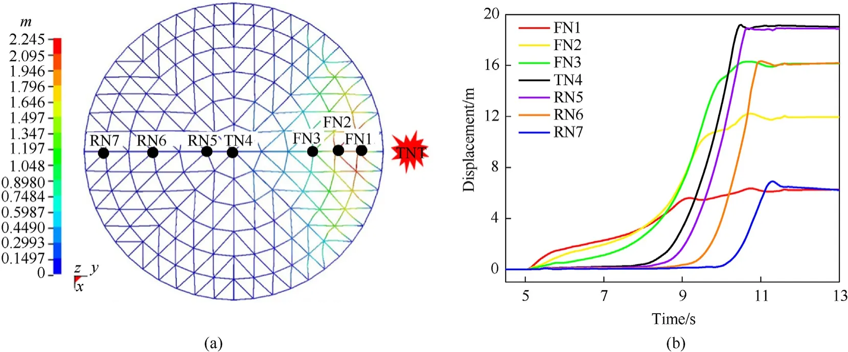
Fig.15. The displacement deformation in overall collapse: (a) Contour of deformation; (b) Displacement histories of major joints.
3.3. Response mechanism
So Fig. 16 and Table 4 describe the deformation and energy distribution of SRDS in the different response modes.

Table 4Energy distribution rate and related response indicators in each response mode.
In minor vibration(Fig.16(a)), the received explosion energy is mainly absorbed by the plasticity of the outermost ring member and roof facing the explosion. Only the first ring facing the explosion shows a slightly plastic deformation due to tension. The internal force and the spatial geometry basically remain unchanged,and 99.85%of the received blast energy is consumed by the plastic deformation of the structure (Table 4).
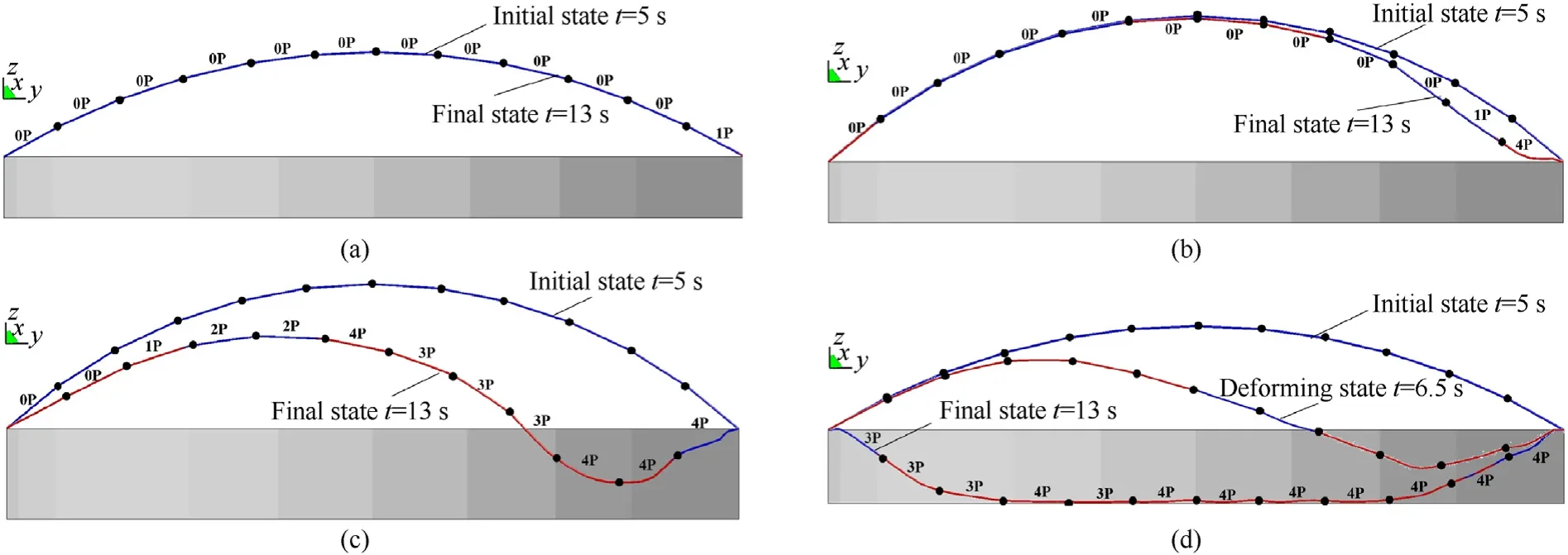
Fig.16. Stress and deformation state of YZ radial members in different response modes: (a) Minor vibration; (b) Local depression; (c) Severe damage; (d) Overall collapse.
In local depression(Fig.16(b)),the received explosion energy is mainly transformed into the local displacement potential energy and the plastic deformation energy of the two outermost rings facing the explosion. The outermost two rings near the explosion experience deep plasticity deformation.The second ring is in mild compression buckling.The top three rings still maintain their initial geometric positions, but their stress state changes from initial compression into tensile deformation. The deformation of the vertex is small, as the ratio of maximum displacement to vertex displacement (Dmax/D1) reaches 15 (Table 4).
In severe damage(Fig.16(c)),the explosion energy increases the displacement potential energy and the plastic deformation energy of most members (Table 4). The structure loses its initial spatial geometry,and most members are in tension deformation and enter deep plastic deformation.
In the overall collapse (Fig. 16(d)), the whole structure finally buckles into deep plasticity and completely loses the initial spatial geometry. The explosion energy is fully converted into the plastic energy, the potential energy, and the damping energy (Table 4).
Different response modes can be distinguished according to the stress and displacement state near the vertex.Fig.17 illustrates the stress-time history of the RB5 member. In the minor vibration response mode,RB5 stays in a compression state and vibrates freely at the initial compression equilibrium position. In both local depression and severe damage,RB5 member is instantly subjected to a relatively strong tensile force but rapidly enters an elastic state and then tends to be stable.In overall collapse,to fully consume the received explosion energy, RB5 is in a tensile yield state with high amplitude and long duration. The ratio of maximum to vertex displacement (Dmax/D1) also differs for each response mode(Fig.18). In both minor vibration and local depression,Dmax/D1is large, which indicates considerable local deformation. However,Dmax/D1tends to be 1 in the case of severe damage and overall collapse,because the maximum deformation position is close to the vertex.Fig.18 shows that in the overall response index,4 P is close to 0 in minor vibration,less than 30%in local depression,and more than 30%in severe damage and overall collapse,but not more than 60%in severe damage.Experimental results of case 1 and 2 are also verified in Fig. 18. Therefore, 4 P and the stress of the vertex member can be used to identify the response mode of SRDS subject to external explosion.
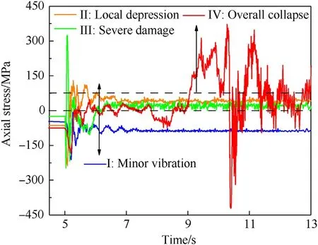
Fig.17. Stress time history curves of RB5 in each response mode.
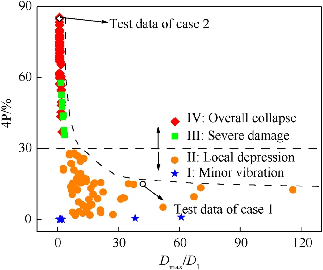
Fig.18. Relation diagram of each response index in each response mode.
4. Conclusions
This work developed and validated a reliable analytical model by small-scale field experiments, to study the blast flow field evolution and predict the response of single-layer reticulated dome structures (SRDS) under external surface burst explosions. The following are the conclusions of this study:
(1) Structural deformation is not evident in the loading area when the blast wave is reflecting and flowing around the SRDS, and some deformation appears after the end of explosive loading. Fluid—structure interaction can be negligible for such large span space structures under external long-range blast loading,so directly applied load method can be tried in further work, which can greatly enhance the computational efficiency.
(2) Four response modes of SRDS under external blast load are identified, namely minor vibration, local depression, severe damage, and overall collapse. In all cases the explosion energy received by structure is mainly consumed by the plastic deformation of each component and the displacement potential energy of the structure. The transformation ability and the degree of participation of the SRDS to the blast loading affect the plastic development and the level of deformation,and thus give rise to different response modes.
(3) The stress characteristics of the vertex members and the deep plastic deformation ratio of 4 P are useful indicators of the response mode. The amplitude of residual stress could distinguish minor vibration from overall collapse, and 4 P could distinguish local depression from severe damage.
(4) Further research illustrating the anti-explosion performance improvement method of resistance to progressive collapse should be conducted. Multiple failure paths and strengthening the main control factors should be proposed in a further study. Furthermore, more research work on a performance-based structural explosion risk model should also be developed to guide the defence technology design.
Declaration of competing interest
The authors declare that they have no known competing financial interests or personal relationships that could have appeared to influence the work reported in this paper.
Acknowledgements
The authors wish to thank the financial support from the China Postdoctora Science Foundation (project No. 2021M690406) and also the financial supports from the National Natural Science Foundation of China (project No.51708521, 51778183).
杂志排行
Defence Technology的其它文章
- A review on lightweight materials for defence applications: Present and future developments
- Study on the prediction and inverse prediction of detonation properties based on deep learning
- Research of detonation products of RDX/Al from the perspective of composition
- Anti-sintering behavior and combustion process of aluminum nano particles coated with PTFE: A molecular dynamics study
- Microstructural image based convolutional neural networks for efficient prediction of full-field stress maps in short fiber polymer composites
- Modeling the blast load induced by a close-in explosion considering cylindrical charge parameters
