Numerical study on dynamic properties of rubberised concrete with different rubber contents
2023-07-04LeiPnHongHoJinCuiThongPhm
Lei Pn , Hong Ho , Jin Cui , Thong M. Phm
a Guangzhou University-Curtin University Joint Research Centre for Structural Monitoring and Protection Against Multi-Dynamic Hazards, School of Civil Engineering, Guangzhou University, China
b Guangzhou University-Curtin University Joint Research Centre for Structural Monitoring and Protection Against Multi-Dynamic Hazards, School of Civil and Mechanical Engineering, Curtin University, Australia
c School of Civil Engineering, Tianjin University, China
d Centre for Infrastructural Monitoring and Protection, School of Civil and Mechanical Engineering, Curtin University, Australia
Keywords:Rubberised concrete Meso-scale model Numerical simulation Strain rate effect Dynamic increase factor
ABSTRACT
1. Introduction
Rubber pollution from waste vehicle tyres has become a serious environmental problem, hence technologies for recovery, treatment and reuse of waste tyres have attracted worldwide attention.The treatment of large quantity of waste tyre rubber is extremely hard and costly because the natural decomposition time of rubber is very long and burning used tyres causes noxious plumes of thick smoke.Therefore,these used rubber tyres should be appropriately recycled.In previous studies[1—6],waste tyre rubber can partially replaces natural aggregates in concrete and it can be used in the construction industry, which has been mentioned. Rubberised concrete(RuC)is green lightweight concrete using rubber particles from used tyres instead of ordinary aggregates. Previous studies have shown that adding rubber aggregate can effectively improve the impact resistance of concrete because rubberised concrete shows great energy absorption performance when subjected to impact load impact load[7],which is the result of increased particle friction between the cementitious matrix and the crumb rubber particles [8]. Because of its strong ability to absorb energy, rubberised concrete has potential to be used in practical projects, e.g.roadside barriers and paver blocks [2,7,9]. Using rubberised concrete for roadside barriers can reduce peak impact force and acceleration, and thus protect drivers and passengers from potential injury.
Concrete subjected to a high rate load behaves different from a static load. The compressive properties of concrete within a large strain rates range have been studied in previous experimental studies [10,11]. It was indicated that concrete-like material is sensitive to strain rate. Compared to static loads, the mechanical properties of concrete such as strength, deformation and energy absorption capacity could increase under dynamic load due to the strain rate effect which is reported in many studies[12—14].Inertial effect [15], failure modes [16,17] and viscosity effect [18] greatly affect the dynamic performance of concrete. The dynamic behaviour of concrete at high rate loads is also influenced by the size and percentage of coarse aggregate [19,20]. Dynamic increase factor(DIF)for concrete compressive strength is the ratio of the dynamic compressive strength to quasi-static compressive strength. The strength increase at different loading rates can be expressed by this value. In order to estimate the compressive DIF, several empirical formulae for normal concrete were put forward [21—23]. Hao and Hao [24]. performed numerical studies on the influences of aggregate size and volume on the DIF, and concluded that they should not be neglected in determining DIF. Hao et al. [25] also conducted high-fidelity numerical simulations to investigate the contributions of lateral inertial confinement to the DIF directly obtained from laboratory testing data.And a method to acquire the real dynamic properties of materials is proposed by eliminating the contribution of lateral inertial confinement to the strength increment in the test data.
Some previous studies [26—29] have indicated that the compressive strength of rubberised concrete also shows the strain rate sensitivity.The composition of rubberised concrete is similar to conventional concrete except containing rubber aggregate.Different scholars have done some research on the quasi static mechanics of RuC [1,3]. However, the research on dynamic compression performance of rubberised concrete is very limited.Topcu[30]carried out an earlier investigation on characterising the dynamic properties of rubberised concrete through drop-hammer tests and found that when coarse and fine aggregate were replaced by rubber particles,the plastic energy absorption capacity of concrete was higher. Atahan et al. [7] found that rubberised concrete had the best impact resistance when the volume replacement amount of coarse aggregate is 20—40%. Recently, the dynamic compressive properties of rubberised concrete were evaluated by SHPB test and found that under impact loads, rubberised concrete properties,like normal concrete,were sensitive to strain rate[29,31].The dynamic compressive strength of rubberised concrete was higher than its corresponding static strength and it increased with strain rates. The impact resistance and fracture toughness of rubberised concrete were substantially strengthened.At the same time, rubberised concrete can also delay the development of cracks,and crack resistance improves with the increase of rubber crumb [29,31,32]. It has also been found that rubberised concrete exhibits better energy absorption capacity compared with normal concrete[26,28].The rubberised concrete has better impact resistance and fracture toughness than the corresponding normal concrete.However,Liu et al.[26]put forward opposite observations that rubberised concrete has a lower DIF than conventional concrete.There have been neither comprehensive explanations nor DIF for the sensitivity of RuC with different rubber contents.
Experimental dynamic tests on concrete are difficult and expensive. Also, the experimental tests could not record all the necessary characteristics, i.e., stress distribution and stress evolution, which means the numerical investigation is the necessary supplement to the experimental study. With the advancement in computational mechanics and computer power, high-fidelity numerical models can be developed to simulate experimental tests.Some researchers have used different numerical methods to study mechanical properties of concrete. Xiao et al. [33] researched the stress distribution in recycled aggregate concrete under uniaxial compression by using two-dimensional finite element model which considered the action of the interfacial transition zone(ITZ).Pham et al.[34]developed a 3-dimensional finite element model of precast recycled aggregate concrete(RAC)using the platform Open Sees in developing a complex nonlinear model under seismic loading.Li et al.[35]used the discrete element method to establish a mesoscopic numerical model composed of irregular cement slurry and gravels to study the compressive properties of recycled concrete.Numerical simulation has been adopted in many previous studies [36—38] to investigate the characteristics of concrete specimens under high velocity impacts.Chen et al.[36]numerically studied the behaviour of concrete materials in high strain rate spalling tests using a meso-scale model,and proposed an empirical relation to correct the spalling test results of non-aggregate mortar specimens. Huang et al. [37] established 2D and 3D meso-scale concrete models to study the dynamic damage and fracture of concrete under compression with strain rates up to 100 s-1,revealing the dynamic failure mechanism of concrete. Zhou et al.[38]developed procedures to generate 3D mesoscale finite element models with realistic aggregate shapes and studied high strain rate effect of concrete. The numerical simulation of concrete materials at high strain rates can expand the limitations of experimental tests,and a large number of simulations can be carried out to obtain further results. For rubberised concrete, some studies have also used numerical method to study their dynamic performance. Shi et al. [39] established a random mesoscale model of recycled rubber-filled concrete, which included mortar, coarse aggregates and recycled rubber particles, and investigated the compressive behaviour of it at high strain rates. Yang et al. [40] numerically studied the performances of the rubber concrete slabs under blasts and found that the rubber concrete slab has a good energy dissipating capacity. Feng et al. [41] modified the Karagozian and Case concrete (KCC) model in LS-DYNA to make it conform to the mechanical properties of rubber concrete, and studied the blast resistance of rubberised concrete under explosion loads. In this study, the SHPB tests of rubberised concrete specimens are numerically simulated. It is generally believed that the different failure modes of specimens under static and dynamic loads cause the real DIF of the inhomogeneous concrete material [15,37,38].Under static loads, cracks slowly initiate and widen in the weak zone of concrete. However, under dynamic loads, the concrete specimen is loaded so fast, such as coarse aggregate and others parts with high strength in concrete may also be damaged.In order to capture these phenomena, it is necessary to model the inhomogeneity and heterogeneity of concrete, which can be modelled by using meso-scale concrete models [36,42].Therefore,the strain rate effect on rubberised concrete should be examined by using a meso-scale concrete model considering mortar matrix,randomly distributed coarse aggregates and rubber crumbs.In this paper,the effect of strain rate on rubberised concrete is studied by a meso-scale rubberised concrete model. And the outputs of the developed numerical model are verified against available SHPB testing data. Seven rubber contents i.e., 0%, 5%,10%,15%, 20%, 25%and 30% by volume were considered in this paper. The numerical model captured the dynamic compressive strength of RuC up to 210 s-1. The formulae of the dynamic increase factor(DIF)considering the rubber content and strain rate were derived accordingly for practical applications.
2. Development and calibration of numerical model
2.1. Brief introduction of SHPB experiment
SHPB systems have been widely used to evaluate the dynamic mechanical characteristic of concrete [43,44]. An SHPB system is composed of an incident bar, a transmitted bar and a specimen,which is sandwiched between the incident and transmitted bars.The numerical model must be verified by some testing results to prove the reliability of the simulation.Therefore,in order to prove the reliability of the numerical model, the experimental results from SHPB tests reported in Ref. [45] are simulated in this study.Fig. 1 gives an illustration of the used SHPB testing system. The incident bar is 5500 mm, the transmission bar is 3000 mm, and their diameter is 100 mm. The density, elastic wave velocity and Young's modulus of the φ100 mm stainless steel bars are 7800 kg/m3,5064 m/s and 240 GPa,respectively.The size of the specimen is 100 mm in diameter and 50 mm in length.
The theory of one-dimensional stress wave propagation theory points out that, by measuring the reflected wave (εR) and transmitted wave (εT), the stress (σ), strain rate (ε•) and strain (ε) of the specimen can be derived [46] as follows:
whereA,EandC0are the cross-section area,Young’s modulus and elastic wave velocity of the bars, respectively; L and ASare the length and the cross-section area of the tested specimens,respectively.
The strain rate of the specimens is not constant and changes.Previous studies[47,48]also mentioned that the strain rate cannot be simply regarded as a constant during the loading. Typically,there are three methods to determine the representative strain rate i.e., the strain rate corresponding to the peak stress in the stressstrain curve, the average slope of the rising stage of the stressstrain curve and the average value of strain rate during the whole experiment[48].To make it consistent with the experimental study[45],the strain rate of the specimen at the maximum stress is used as the representative strain rate.
2.2. 3D rubberised concrete meso-scale model
A 3D meso-scale model of RuC considering randomly distributed rubber crumbs with different sizes is developed in this section.Through comparing the experimental results and numerical results of cylinder specimens under low and high strain rates, the reliability of the established 3D meso-scale model and the modelling method is validated.
2.2.1. Establishment of 3D meso-scale model
In the meso-scale model, it is assumed that the concrete specimen is a composite material composing of aggregates, rubber crumbs and mortar matrix. By using the FORTRAN computer language, a program for generating the random distribution of the aggregates and rubber crumbs for the meso-scale concrete model was written.
In order to consistent with the adopted experimental study[45],the size of aggregates and rubber crumbs is set to 1—10 mm in the meso-scale model. According to the mixing of concrete specimens in Ref.[45],aggregates accounted for 45%of the total volume of the specimens, the rubberised concrete specimens with the rubber contents of 0%,15%and 30%,i.e.,the equivalent volume percentage of natural aggregates were replaced by rubber crumbs,were mixed and tested.In this paper,the numerical models are developed first accordingly to verify the accuracy of the numerical simulations.The first step is to build a homogeneous meshed finite element model.A cylindrical concrete specimen, with a length of 50 mm and a diameter of 100 mm,is meshed by 1.0 mm Lagrange solid elements since this mesh size was recommended by Ref. [49] to generate reliable results. Then, the random distribution of the aggregates and rubber crumbs is generated by a FORTRAN program and map them into the meshed homogeneous finite element model [49].
Step 1: Generation of coarse aggregates and rubber crumbs.
In this study, aggregates and rubber crumbs are assumed to be randomly sized spheres,which are randomly distributed inside the concrete specimen. The size distribution of aggregates and rubber crumbs follows Fuller's curve. It defines the ideal density and strength of the aggregate particles gradation of the concrete mixture[50] and given by
whereP(d)represents the passing percentage of the coarse aggregates with aperture diameterd;dmaxrepresents the maximum size of aggregate particles;nis the exponent of the equation, with a value range of 0.45—0.7. In the present study, 0.5 is taken [49].
The generation and placement of random aggregates are divided into sub-steps:
(1) Randomly generate the diameter and location of an aggregate or a rubber crumb;
(2) Check whether the boundary condition meets the requirement that the aggregate and the rubber crumbs have no overlap, and the aggregate is within the boundary of the specimen;
(3) If the generated aggregate or rubber crumb meets the boundary conditions,it is placed in the specimen area;if not,delete the aggregate or rubber crumb and execute another generation until the generated aggregate or rubber crumb meets the boundary conditions.

Fig.1. SHPB test system.
(4) Repeat the above steps continuously until the target percentage of aggregates and rubber crumb is attained.
Step 2: Mapping aggregate and rubber crumb to the homogeneous finite element model.
Firstly, the meshed finite element model of the homogeneous specimen is established. Then, the keyword file of the homogeneous finite element model of the specimen is modified by a FORTRAN program, i.e., mapping the aggregate and rubber crumb generated in the previous step into the homogeneous specimen.The placement of aggregates into the finite element model includes the following three sub-steps:
(1) Calculate the central coordinate of each element in the finite element model;
(2) Call the spatial location information of aggregates or rubber crumbs generated in the first step;
(3) Analyse the position relationship between aggregates or rubber crumbs and elements. If the central coordinate of an element is inside one of the aggregates or rubber crumbs,specify the aggregate material or rubber crumb to the element accordingly; if not, fill the material property with mortar.
The Interfacial Transition Zone (ITZ) in concrete is supposed to be the vulnerable zone where cracks initiate.For RuC,there is also an interfacial transition zone between rubber crumb and mortar.Concrete was generally divided into three phases, namely cement mortar, aggregate and ITZ in some previous investigations using concrete meso-scale models[51,52].At present,the characteristics of the ITZ have not been well understood[42].The inclusion of ITZ in a numerical model may bring uncertainty to numerical simulation.Furthermore,10—50 μm is generally considered to be its actual thickness [53]. If such a thickness is adopted in a 3D meso-scale model, it will cause an extremely large number of elements,which is too difficult for the current computer ability.Therefore,the interface transition zones between an aggregate vs mortar and a rubber crumb vs mortar are not considered in this paper,and they are assumed to have perfect bond by sharing the same nodes.This simplification has been adopted by many previous studies of mesoscale concrete models and yielded reliable predictions [38,49]. On the other hand, the mechanical properties (such as Young’s modulus)of rubber crumb and mortar are very different,therefore,the severer damage at ITZ could be naturally considered to some extent because of uncoordinated deformation of the two materials.
As shown in Fig. 2, a three-dimensional meso-scale (3D) numerical model is established to simulate the SHPB test in Ref.[36].

Fig. 2. A typical 3D meso-scale model of rubberised concrete with 15% rubber crumb: (a) Concrete; (b) Mortar; (c) Aggregate; (d) Rubber crumb.
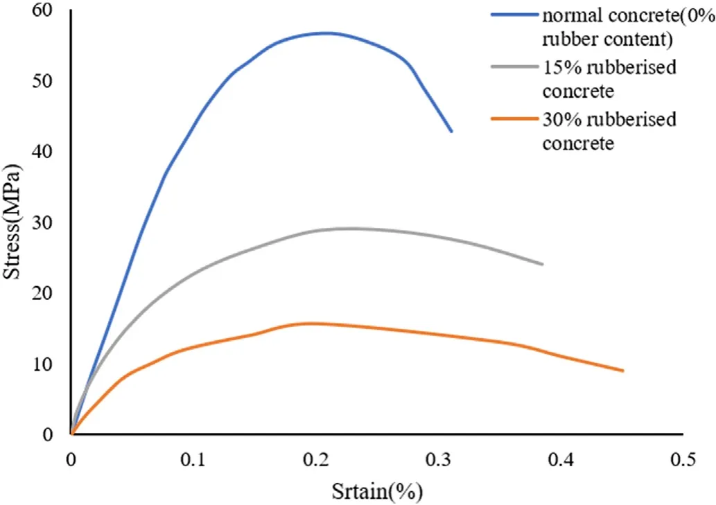
Fig. 3. Stress-strain curves of rubberised concrete with different levels of rubber contents.
2.2.2. Material model
In the present research,the simulation of mortar and aggregates adopts the plastic-damage model for concrete in LS-DYNA [54]developed by Malvar et al.[55](Mat_072R3)[36].Previous studies[56,57] have confirmed that this material model can effectively simulate and forecast the performance of concrete structure. The model considers the strain rate effects and the damage of the material by using three fixed shear failure surfaces, i.e., the yield surface,the maximum surface and the residual surface which could describe the damage characteristics of the material under different loading stages. The strain rate effects under tensile and compressive loads are considered by using the tensile dynamic increase factor(TDIF)curve and compressive dynamic increase factor(CDIF)curve,respectively.In the simulation,the parameters of K&C model are used by automatic parameter generation. Table 1 shows the input material parameters.

Table 1Material parameters of mortar and aggregate [56].
Rubber-like materials have highly non-linear stress—strain behaviour and show very large strain. A strain-energy density function can be used to derive their stress-strain relationship.In the present study,*Mat_Mooney-Rivlin_Rubber(MAT_27)is employed to model the rubber crumb. Mooney proposed the Mooney-Rivlin model in 1940, and then in 1984, the most general form of strain energy function was modified by Rivlin [58,59]. At present, the most commonly used strain energy density function model is
whereC10,C01,anddare Mooney constant determined by material test,I1andI2are the first and second Green strain invariants,respectively, andJ= 1 for incompressible rubber. Since it contains two parameters,it is called a two-parameter Mooney-Rivlin model.Only poisson's ratio of rubber crumb and parameterC10,C01need to be input in the LS-DYNA. As shown in Table 2, the input material parameters of rubber crumb are as follows:

Table 2Material parameters of rubber crumb [60].
2.2.3. Strain rate effects
The mechanical properties of concrete under impact and blast loads are different from those under quasi-static conditions in terms of both the compressive and tensile behaviours [15,61]. The performance of concrete is affected by strain rate as discussed in previous studies [15,62,63]. the dynamic behaviour of the mortar matrix is simulated by adopting DIFs recommended by CEB [21],which are obtained from a large number of experimental test data on mortar matrix and concrete. The CEB recommendation for compressive DIF (CDIF) is shown below
wherefcdis the dynamic compressive strength in MPa;fcsis the quasi-static uniaxial compressive strengths in MPa;s-1.
The tensile DIF (TDIF) recommended by CEB is as follows:
whereftdandftsare the dynamic and quasi-static uniaxial tensile strengths in MPa,respectively,and=1×10⁻⁶s-1.The DIFs for aggregates are adopted from previous studies [24,64]. The compressive and tensile DIFs of natural aggregates are shown below:
Due to the limited test data,when the strain rate over 50 s-1,a constant value is adopted for the TDIF of granite aggregates to avoid overestimating TDIF[24,64].
2.2.4. Model validation
(1) Quasi-static compressive test
To verify the developed numerical models,the quasi-static tests of the rubberised concrete with the rubber contents of 0%,15%and 30%reported in Ref.[45]are simulated in the present study.When the rubber content is 0%,15% and 30%, the corresponding experimental quasi-static compressive strengths of rubberised concrete were 56.33 MPa,27.96 MPa,and 16.33 MPa,respectively.No stressstrain curve was given in Ref.[45],therefore only static compressive strengths can be compared.
Similar to the experiment,in the numerical model,the specimen is placed between two rigid loading plates.Restrict all directions of the bottom plate. And the upper plate can be moved in a vertical direction by controlling the movement speed of 0.2 mm/s. For the rigid loading plates, the elastic material model *MAT_ELASTIC(MAT_001)in LSDYNA is used,in which the yield strength of steel is 300 MPa,the mass density is 7800 kg/m3and the Young's modulus is 200 GPa. The contact between the rigid loading plates and the specimen is simulated by the contact algorithm named*Contact_Automatic_Surface_to_Surface and the friction coefficient is set to 0.105 [56].
Fig.3 shows the stress-strain curves of rubberised concrete with different rubber contents obtained by numerical simulations. The comparison of numerical simulation results and experimental test results of quasi-static compression test is given in Table 3.It can be seen that the quasi-static compression test of numerical simulation is in good agreement with the experimental test results. The effectiveness of the meso-scale concrete model in this study is verified.

Table 3Model verification at the quasi-static condition.
(2) SHPB test
As shown in Fig. 4, the numerical model of the SHPB test includes an incident bar, the meso-scale concrete specimen and a transmitted bar. The incident stress history curve obtained from the SHPB test is applied on one end of the incident bar.The mesh size of the elastic steel bars is set to 10 mm (cubic Lagrange solid elements).While the mesh size of the specimen is set to 1 mm becausethe smallest size of aggregates and rubber crumbs considered in this meso-scale model is 1 mm.The chosen meshes have passed the convergence test.In addition,the*MAT_ADD_EROSION function in LS-DYNA is used to automatically delete elements with large deformation to make sure the calculation continue. In this study,the failure criterion is set as the compressive strain value of 0.15,which yields good agreement with the experimental results.
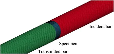
Fig. 4. Numerical model of SHPB compression test.
Fig. 5 compares the experimental and numerical stress-time histories recorded on the incident bar and the transmitted bar during tests of rubberised concrete with different rubber contents,which indicates that the simulated stress histories are close to the test data. Fig. 6 shows the comparison of dynamic compression stress-strain curves. It can be seen that the stress-strain curves obtained by simulation are also fit good with the test results.

Fig. 5. Stress histories from tests and simulations: (a) Normal concrete (0% rubber content); (b) 15% rubberised concrete; (c) 30% rubberised concrete.

Fig. 6. Experimental and numerical stress-strain curves: (a) Normal concrete (0%rubber content); (b) 15% rubberised concrete; (c) 30% rubberised concrete.
The dynamic compressive strengths obtained from numerical simulations and tests are presented in Table 4. It can be seen that the error ranges between 0.14% and 7.8% by comparing the numerical simulation results with the test results, which indicates that the established meso-scale finite element model can well predict the dynamic compressive strength of rubberised concrete.

Table 4Validation with experimental data of SHPB compression test.
To further verify the reliability of the developed model, failure modes of rubberised concrete with different rubber contents in the simulation are compared with those observed in the tests. Fig. 7 and Fig. 8 show the progressive failure of rubberised concrete with 0% and 15% rubber contents, respectively. The failure process of 30%rubberised concrete was not presented in Ref.[45],therefore the comparison of 30% rubberised concrete cannot be made. From the figure,it is obvious that the crack and failure modes of concrete in the meso-scale model numerical simulations match well with those in the tests. The results have shown that the established numerical models can predict well the behaviour of rubberised concrete with various rubber contents under different strain rates.
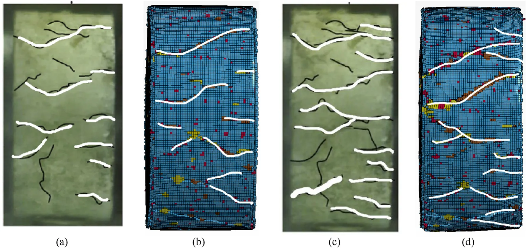
Fig. 7. Comparison of failure modes of 0% rubberised concrete (experiment vs simulation): (a) 120 μs test result; (b) 120 μs simulation result; (c) 200 μs test result; (d) 200 μs simulation result.
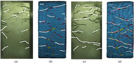
Fig.8. Comparison of failure modes of 15%rubberised concrete(experiment vs simulation): (a)200 μs test result;(b) 200 μs simulation result;(c)1800 μs test result;(d)1800 μs simulation result.
3. Strain rate effect on rubberised concrete with different rubber contents
3.1. Numerical results and discussions
As can be seen from Fig. 7 and Fig. 8, cracks develop from both sides to the middle area of the specimens. Afterwards, more fracture is observed in the intermediate zone and develops arbitrarily.As shown in Fig. 7 and Fig. 8, rubberised concrete slows down the development of cracks.At 200 μs,compared with normal concrete,the number of cracks in 15% rubberised concrete is much less.Normal concrete was crushed into small pieces soon after 200 μs while 15%rubberised concrete specimen remains intact at 1800 μs with a similar number of cracks to that of ordinary concrete specimen at 200 μs.
To study the effects of the rubber content and strain rate on the dynamic mechanical properties, rubberised concrete with 7 different rubber contents subjected to a wide range of strain rates of 10-5-about 210 s-1was simulated.Table 5 shows the strengths of rubberised concrete with different rubber contents. The stress strain curves of rubberised concrete containing different rubber contents under different strain rates are given in Fig. 9—Fig.15.
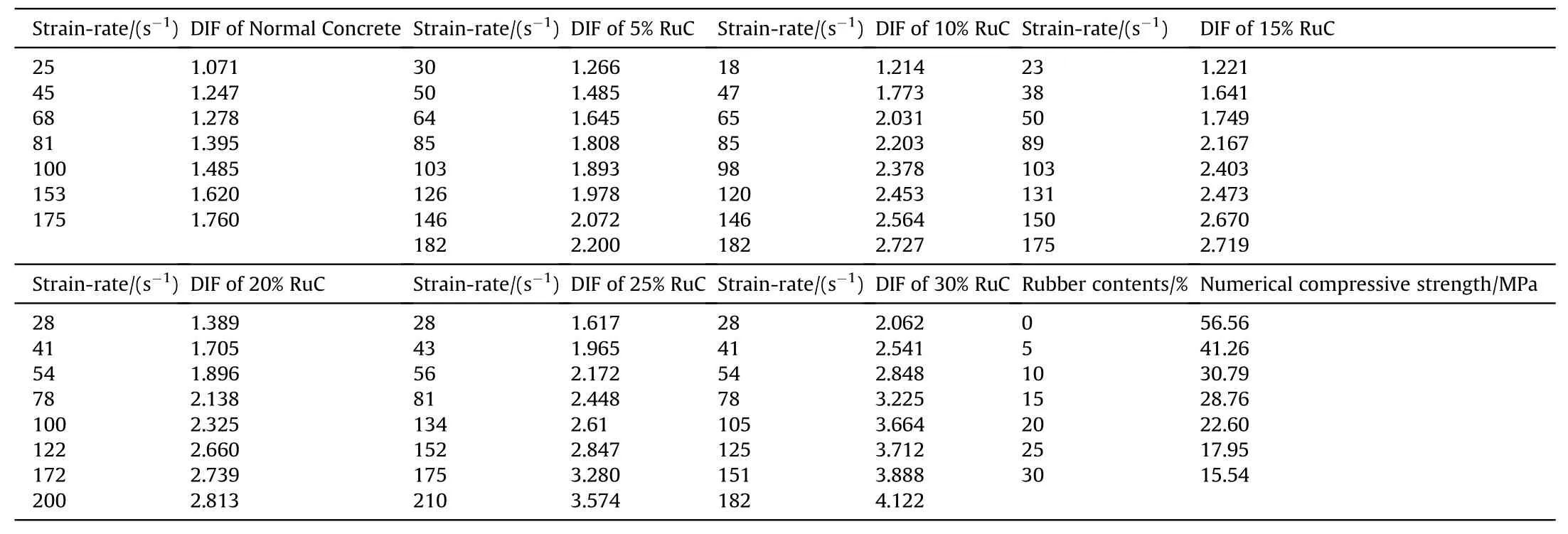
Table 5DIF of rubberised concrete with different rubber contents.

Fig. 9. Stress-strain curves of normal concrete (0% rubber) at different strain rates.
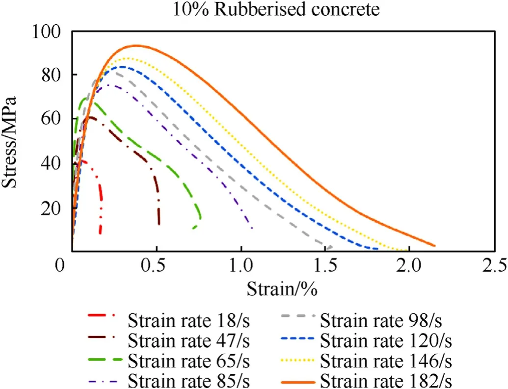
Fig.11. Stress-strain curves of 10% rubberised concrete at different strain rates.
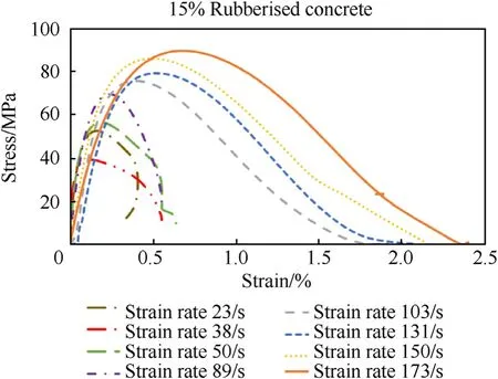
Fig.12. Stress-strain curves of 15% rubberised concrete at different strain rates.
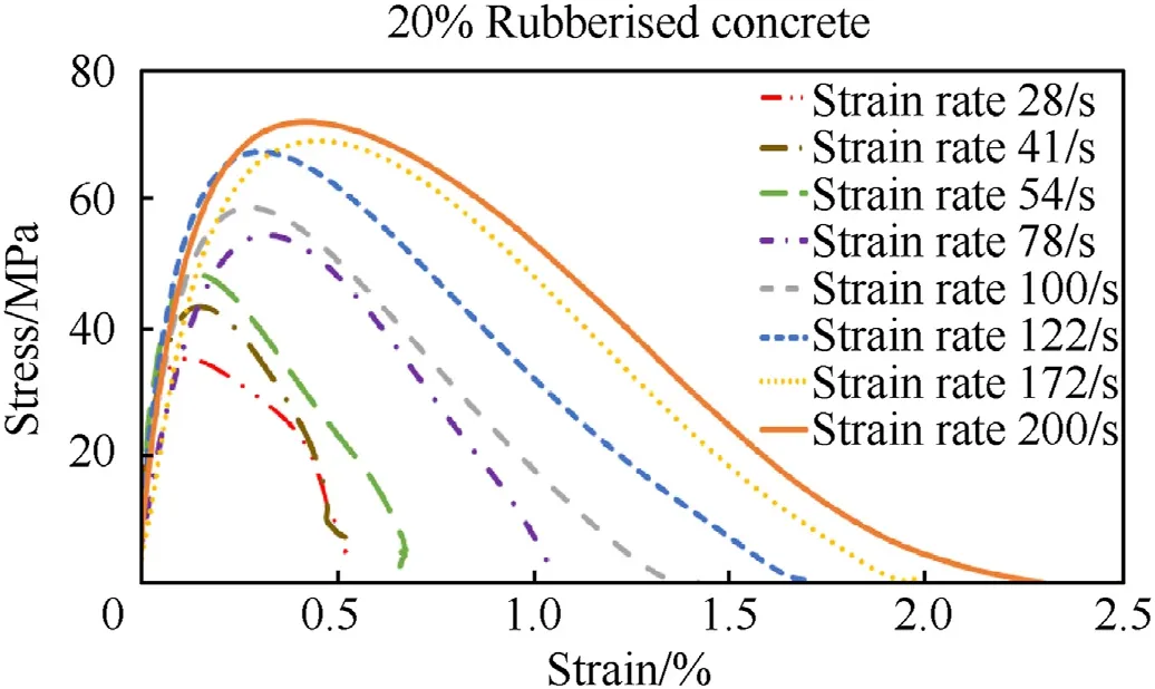
Fig.13. Stress-strain curves of 20% rubberised concrete at different strain rates.
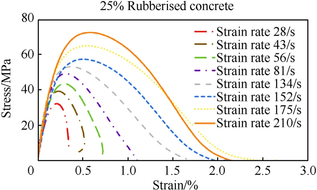
Fig.14. Stress-strain curves of 25% rubberised concrete at different strain rates.

Fig.15. Stress-strain curves of 30% rubberised concrete at different strain rates.

Fig.16. Strain rate sensitivity of rubberised concrete compressive strength.
Shown in Fig.9—Fig.15,the compressive strength of rubberised concrete increases with the strain rate which resembles the previous studies on the strain rate effect of concrete-like materials[10,11]. Besides, the critical strain (strain at the maximum stress)also increases with the strain rate while the elastic modulus does not show an obvious or consistent strain rate sensitivity for rubberised concrete,which oscillates with the strain rate,especially for the cases without and with 15% rubber contents. Meanwhile, the elastic modulus of rubberised concrete does not exhibit considerable changes when the strain rate increases. This phenomenon is interesting and requires further investigations to unveil the true mechanism.
The dynamic increase factor(DIF)is used to assess the increase in dynamic compressive strength relative to static compressive strength for concrete with different rubber contents.Table 5 shows DIF of rubberised concrete containing various rubber contents under different strain rates.Among which,30%rubberised concrete shows the highest DIF,while that of normal concrete is the lowest and the DIF increases with the strain rate.It can be concluded that the strain rate effect of rubberised concrete becomes more sensitive with the increase of rubber content,which means adding rubber to concrete can more prominently enhance the compressive strength of concrete at high loading rates.The cracking arrest mechanism of rubber can be used to interpreted the increase of DIF. When the high strain rate load is applied on the specimen, cracks begin to appear and cross over the rubber aggregates, then the rubber particles reduce the crack velocity through stress relaxation [65]. At low loading rate,the crack development and the stress change are synchronous. When the loading rate is up to a certain extent, the velocity of the crack development lags behind that of loading stress resulting in the improvement of compressive strength under high loading rate. At this failure stage, the rubber could slow down the crack development velocity and limits the penetration of the main cracks. Due to the elastic characteristics of rubber itself, it can eliminate the stress concentration in the void, restrict the generation and development of micro-cracks when concrete is subjected to impact loads, so as to improve the impact resistance of rubberised concrete[8].
Previous studies have mentioned that the improvement of dynamic compressive strength depends not only on the material properties, but also on the structural effect, especially under high impact loads. According to previous studies [47,64], the improvement of dynamic compressive strength is also related to the lateral inertial confinement, which leads to an overestimation of DIF, and this improvement needs to be removed to gain the real material strain rate effect. Some previous studies on the DIF of normal concrete have mentioned that lateral inertial confinement contributions are about 4%—13%for φ100×50 samples when the strain rate is in the range of 10—80 s-1[43], while the corresponding contribution for φ100x50 specimens was 13.68% at 200 s-1as reported by Hao et al. [25]. In this study, since the strain rate ranges from 20 to 210 s-1, a reduction factor of 6% at the strain rate of 18—64 s-1and 10%at the strain rate of 64—210 s-1are assumed and applied to the simulated data to remove the inertial confinement effect.
In Fig. 16 and Fig. 17, the strain rate range of 18—210 s-1was divided into six groups to research the strain rate sensitivity of concrete with different rubber contents under similar strain rates.The DIFs increase with the rubber content at a certain rate which confirms that the sensitivity of rubberised concrete increases with the rubber content.Pham et al.and Xu et al.[45,66]also found that the DIF of rubberised concrete and rubberised geopolymer concrete[67] had a linear positive correlation with the strain rate, which is similar to this study. However, Liu et al. [26] pointed out that rubberised concrete has a lower strain rate sensitivity than normal concrete, which is inconsistent with the results of this study.Besides, Pham et al. [20] and Liu et al. [26] also found that the DIF also substantially increased with the increase of rubber aggregates particle size.In Ref.[26],the maximum size of the rubber aggregate was 2 mm,while the maximum size in this study was 10 mm.This difference may explain why Liu et al. [26] had different observations.Meanwhile,the critical strain(strain at the maximum stress)does not exhibit an obvious relation to the rubber content but it increases with the strain rate,as shown in Fig.17.
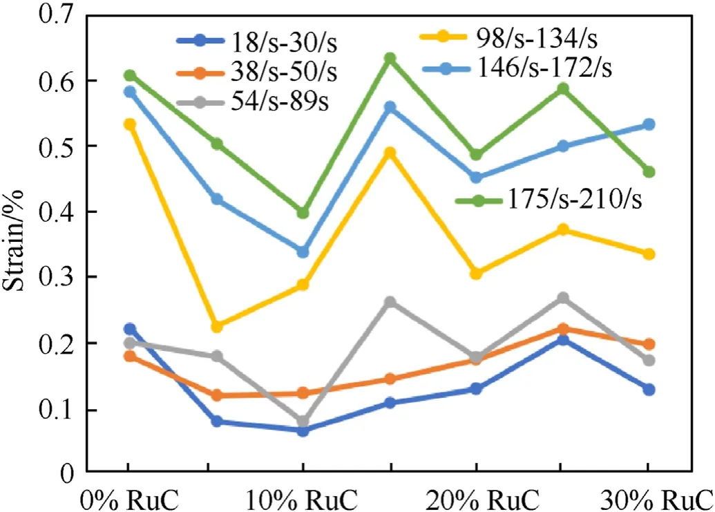
Fig.17. Strain rate sensitivity of critical strain of rubberised concrete.
3.2. Definition of DIF used in the rubberised concrete model
Fig. 18 shows the comparison between the DIFs of the rubberised concrete in this study. DIFs of the normal concrete from other research [21,25] are also shown for comparison. In general,the DIF of rubberised concrete has a similar trend to normal concrete,in which it increases with the strain rate.The strain rate effect is not very obvious at a low strain rate,but when the strain rate is greater than 30 s-1, it becomes significant. Besides, it also can be shown from Fig.18 that with the increase of rubber content,the DIF also increases gradually. In addition, compared with normal concrete rubberised concrete is more sensitive to strain rate.As shown the data for normal concrete from Refs. [21,25] are higher than those for normal concrete obtained in this study,especially the CEB DIF data[21]are close to those with 10%—20%rubber crumbs.This is because the contribution from lateral inertial confinement effect to DIF is removed in the present data, which leads to smaller DIFs than those obtained directly from impact tests.

Fig.18. Comparison of DIF with different rubber content.
Empirical formulae of DIF of compressive strength for RuC material can be derived similarly to that of the normal concrete. The DIF—strain rate curve of RuC presents a bilinear function.The range of strain rate in the first stage is about 10-5-30 s-1,corresponding to a low strain rate.In the second stage,if the strain rate is over 30 s-1,the increment rate of DIF is much faster.In each stage,DIF is linear with the logarithm of the strain rate. The linear relationship between strain rate and DIF is expressed as follows:

Table 6Parameters of fitting curves of Eq. (14).
The relationship between the four parameters ofa,b,c anddand the rubber content are shown in Fig.19.As shown in the figure,the horizontal axis represents the rubber content and the vertical axis represents the value of the four parameters. The best fitting equations of parametersa,b,c anddas a function of rubber contents are as follows:

Fig.19. Correlation between a, b, c and d and rubber content.
where RuC is the volume percentage of rubber content. These empirical relations, together with Eq. (14), can be used to predict the DIF of rubberised concrete with rubber volume percentages in the range of 0%—30%.
4. Conclusions
This study successfully developed a meso-scale model of rubberised concrete with different crumb rubber contents up to 30%to evaluate the dynamic characteristics of the rubberised concrete.The existing experimental data prove the accuracy of the numerical model. The observations of this study are summarised as follows:
(1). Rubberised concrete shows great impact resistance under high loading rates. Compared with the normal concrete,rubberised concrete slows down the crack expansion and progressive destruction significantly.
(2). Rubberised concrete is a strain rate sensitive material and compared with normal concrete,it is more sensitive to strain rate.With the increase of the rubber content,the strain rate sensitivity of rubberised concrete increases. At the same time,the critical strain does not show an obvious relation to the rubber content but it increases with the strain rate.
(3). DIF formulas for rubberised concrete with various rubber contents were established.The proposed DIF relation can be used to forecast the dynamic strength of rubberised concrete in response analysis of structures under different strain rates and with different rubber contents.
It should be noted that the ITZ between rubber crumb and cement mortar is not considered in the numerical modelling of this study. Although the current numerical model is verified against testing results, it is well known that the adhesion between rubber crumb and mortar is weak,and which is one of the reasons for the low strength of rubberised concrete. Therefore, studying the bonding mechanism between rubber crumb and cement mortar and how would it influences on the static and dynamic properties of rubberised concrete could be an interesting research topic in the future.
Declaration of competing interest
The authors declare that they have no known competing financial interests or personal relationships that could have appeared to influence the work reported in this paper.
杂志排行
Defence Technology的其它文章
- A review on lightweight materials for defence applications: Present and future developments
- Study on the prediction and inverse prediction of detonation properties based on deep learning
- Research of detonation products of RDX/Al from the perspective of composition
- Anti-sintering behavior and combustion process of aluminum nano particles coated with PTFE: A molecular dynamics study
- Microstructural image based convolutional neural networks for efficient prediction of full-field stress maps in short fiber polymer composites
- Modeling the blast load induced by a close-in explosion considering cylindrical charge parameters
