Vibro-acoustic characteristics of multifunctional carbon fiber reinforced panel
2023-07-04LiertGudgnoMriluigiRimondoLuigiVertuioGiuseppinBrrMurizioArenMssimoVisrdi
Liert Gudgno , Mriluigi Rimondo , Luigi Vertuio , Giuseppin Brr ,Murizio Aren , Mssimo Visrdi ,**
a Department of Industrial Engineering, University of Salerno, Via Giovanni Paolo II,132, 84084, Fisciano, SA, Italy
b Department of Engineering, University of Campania “Luigi Vanvitelli”, Via Roma 29, I-81031, Aversa, Italy
c Department of Industrial Engineering, Aerospace Section, University of Naples “Federico II”, Via Claudio 21, 80125, Naples, Italy
Keywords:Composite materials Electrical properties Damping Tunneling atomic force microscopy (TUNA)Vibro-acoustic properties
ABSTRACT
1. Introduction
The extensive use of composite materials, namely Glass Fiber Reinforced Composites (GFRCs) or Carbon Fiber Reinforced Composites(CFRCs),in aircraft structure involves glass fibers or carbon fibers,generally in the form of fabric,in a non-conductive resin and poor adhesive properties at the joints[1].Furthermore,the current trend in aircraft design is an increasingly massive shift toward the replacement of mechanical systems with electronic systems to manage fly function and increase the safety level through automatization functions. In this contest, strategies based on the modification of matrix material have been proposed as possible solutions to different drawbacks ranging from aspects related to pollution and waste recovery to those strictly related to mechanical performance and integration of functional properties [2—6]. Concerning the functional properties,many of these strategies focus on the establishment of smart materials and electronic control of electrically stimuli-responsive materials. Modification of epoxy resins with carbon nanotubes(CNTs)may transform the electrically insulating resin into a conductive material[7—11],able to respond to electrical signals and allowing easy thermal management[12—15],an increase in adhesive properties[16,17],the integration of self-sensing [18—20], lightning strike protection [21], electropolymerization ability [22]. Another important issue to address in developing aircraft composites is their flame resistance.The epoxy resin between carbon or glass fiber woven can burn under accidental aircraft fire conditions. In order to design a functional resin able to increase its fire resistance, different approaches have been proposed in literature [23]. Specific nanoparticles have been considered good candidates because they are found to enhance fire resistance and char formation of the polymeric material [24—26].CNTs in polymeric matrices have shown to reduce heat release in burning materials very effectively. CNTs dispersed in a resin of aeronautical grade prepared by mixing a tetrafunctional epoxy precursor TetraGlycidyl-MethyleneDiAniline (TGMDA) with a reactive diluent 1—4 ButanediolDiglycidyl Ether (BDE), which facilitates the solubilization of the hardener agent,are able to confer flame and thermal resistance to the hosting matrix [27]. Furthermore, their combination with GPOSS compound and phosphorous hardeners, such as BAMPO has proven to be more effective to increase flame resistance[27,28].While many mentioned properties of the developed functional CFRCs have been extensively studied from the point of view of the flame resistance property and the static mechanical and electrical performance, very limited studies have been performed for the assessment of their damping and acoustic properties. The study of these properties is relevant to understanding the stability of developed components/systems providing information about the energy dissipation of a system under dynamic excitation induced vibrations. Fiber reinforced composites are seen as promising materials because of the potential tailoring of intrinsic damping properties by acting on composition, geometry, and boundary conditions, providing damping of several orders of magnitude higher than that detected for traditional engineered materials [29,30]. In this regard, composites based on nanoparticles represent a class of materials offering a high potential as noise and vibration control solutions, especially in applications where weight reduction is strongly requested[30—33].In recent years, significant studies have been carried out to investigate and improve the acoustic properties of filled polymer composites.Previous studies showed that foaming and the use of nanoparticles such as CNTs improved the soundproofing properties of different composites [31]. CFRCs manufactured using CNTs dispersed in an epoxy resin based on TGMDA and DDS, also containing BAMPO and GPOSS,showed promising damping value and a higher sound transmission loss (STL) at low frequencies, in the normal mode participation region [34]. Combination of these properties, with the functional and smart ones mentioned above,open great opportunities for functional CFRCs, not only with reference to the aeronautical field but also for other technological applications (i.e., automotive and lightweight high-tech applications)where the integration of functional and smart properties are requested.
The present work deals with the experimental characterization of both dynamic and sound insulation properties of a CFRC manufactured with a modified bulk infusion process using a resin formulated to be flame resistant and to contrast electrical insulating properties of epoxy resins. Vibro-acoustic tests have been carried out for the characterization of the damping as well as the transmission loss properties related to micro-handling treatments.The vibration tests,according to the impact technique,were carried out to estimate the modal parameters, and in particular the damping ratio.A high dissipation behaviour has been observed for the manufactured panel for both the low frequency region (pure vibrations) and sound pressure waves domain. Furthermore, electrical properties have been analysed at macro and nanoscale.Tunneling Atomic Force Microscopy (TUNA) was used to analyze the local electrical conductivity of both the multifunctional resin by which the carbon fibers in the panel were impregnated and of the final manufactured panel, named LS1. This technique made it possible to clearly detect a regular distribution of the conductive carbon nanotubes within the multifunctional resin and to observe electrically conductive three-dimensional networks inside the resin through the panel plies.The manufactured panel exhibits very high values in electrical conductivity.
2. Experiment
2.1. Materials and methods
For the preparation of the multifunctional resin used for the impregnation of the carbon fibers, the following compounds were used: a) the epoxy precursor TGMDA (CAS 28768-32-3 chemical formula C25H30N2O4); b) the DDS (CAS 80-08-0, chemical formula 4-(NH₂)C₆H₄₂SO₂); c) the epoxy reactive monomer BDE (CAS 2425-79-8,chemical formula C10H18O4).BAMPO hardener,acting both as a curing agent and a flame retardant, was synthesized through a sequence of steps as already reported in the literature and available in the section “Electronic supplementary information (ESI)” of Ref. [27]. In more detail, for the modified epoxy system, the experimental procedure can be summarized as follows: CNTs(0.5 wt%.) were dry mixed with the hardeners DDS/BAMPO for 10 min at 100 rpm using a ball-mill(Retsch PM400)to disaggregate CNT and further facilitate their incorporation within the epoxy precursors. After milling, the resulting powder was incorporated within the epoxy resin (TGMDA 75 wt% and BDE 25 wt%.) containing GPOSS at 118◦C and mechanically stirred for 20 min in order to dissolve the hardeners.The blend was then ultra-sonicated(Branson S-50D equipment, 200 W, 20 kHz, 13 mm diameter ultrasonic-probe)for 2 min in order to finely disperse the CNTs. The master batch of epoxy nanofilled resin obtained by adopting the described procedure was used to manufacture the CFRC panel,here named LS1. The panel LS1 constituted by 8 plies, 40 cm × 40 cm,was produced using the formulation (TGMDA 75 wt% and BDE 25 wt%). In this matrix, the weight percentages of the different components were: 0.5% CNTs, 5% GPOSS, 53.3% DDS and 46.7%BAMPO. As described in previous papers, traditional infusion approach was practically un-feasible because CNTs increase the viscosity of the system and prevent the resin to flow rapidly and impregnate the fibers on long paths. Moreover, the carbon fibers retain part of the nanotubes as a filter, creating a gradient of CNT concentration.For this reason,a modified infusion process detailed described in Ref.[7]has been adopted.The benefit of this modified infusion process has been described in detail in Ref.[35],where the traditional infusion process has been compared with the modified one.
The curing cycle was set in the following way:
(1) Ramp at 2◦C/min up to 100◦C;
(2) Dwell (until filled resin emerges from preform);
(3) Close vacuum pump-pressure at 4.5 bar,vent open at 2 bars;
(4) Ramp to 120◦C at 2◦C/min;
(5) Dwell of 1 h at 120◦C;
(6) Ramp to 180◦C at 1◦C/min; 7) Dwell of 3 h at 180◦C.
The optical image of the panel LS1 is shown in Fig. 1 and the main physical characteristics in Table 1.

Table 1Main physical characteristic of the laminate panel.
The Limiting Oxygen Index(LOI)(%)value,corresponding to the minimum concentration of oxygen in a nitrogen/oxygen mixture necessary to sustain the combustion of the sample has been evaluated following the standard test method reported in ASTM 2863[37].The DC volume conductivity of the cured multifunctional resin was measured by using disk-shaped samples of a diameter of 50 mm and a thickness of 2 mm using an experimental procedure already described in literature [36].
The in-plane DC conductivity of the LS1 panel was measured according to the method described in Ref.[7]by adopting the fourprobe method on strip samples of about 40 × 17 × 1.6 mm3, as illustrated in Fig. 2.
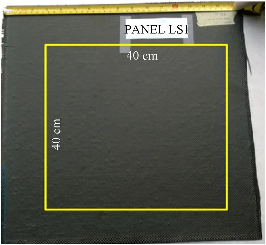
Fig.1. Optical image of the CFRC named LS1.

Fig.2. Geometry of the sample(length=40 mm,b=17 mm,c=1.6 mm),and Set-up for the measurement of the in-plane DC conductivity of the panel.
Both the multifunctional resin and the LS1 panel based on the multifunctional resin were investigated by TUNA technique, after being subjected to a chemical etching [38] which, through the consumption of the resin,discovered the conductive filler in order to evaluate the effectiveness of its distribution within the epoxy matrix and between the carbon fiber plies,respectively.The TUNA measurements were performed in contact mode with an electrically conductive tip of 20 nm and platinum-coated probes having nominal spring constants of 35 Nm-1.For the multifunctional resin,we used the DC sample bias equal to 3 V,current sensitivity equal to 10 pA/V,scan rate equal to 0.500 Hz/s,and number of samples per ramp equal to 512. For the LS1 panel, the scan parameters were instead the following: DC sample bias equal to 2 V, current sensitivity equal to 1 pA/V, scan rate equal to 1.00 Hz/s, and number of samples per ramp equal to 256.The TUNA investigation was carried out without grounding the conductive samples.The four images of Height, Deflection Error, Friction and Tuna Current, taken contemporaneously, were examined using the Bruker software Nanoscope Analysis 1.80 (BuildR1.126200).
MWCNTs were kindly provided by Nanocyl (grade 3100). They were used without any further purification. High resolution scanning electron microscope (HRSEM) micrographs of MWCNTs were obtained with a field emission SEM apparatus (JSM-6700F, JEOL)instrument operating at 3 kV.
3. Experimental results and discussion
3.1. Panel components: MWCNTs, fibre, resin and void content of the manufactured panels
High resolution transmission electron microscope (HRTEM)images of MWCNTs at two different magnifications are shown in Fig. 3.

Fig. 3. HRTEM micrographs of MWCNTs at two different magnifications.
HRSEM micrographs detected for the CNT used in this work highlighted a diameter of MWCNTs frequently ranging between 9 and 19 nm;but also higher diameters up to 30 nm were observed in some images. The distance between walls was found ranging around 0.35 nm and a number of walls in nanotubes varying from 4 to 11 was detected. Nanotubes length was found to be from hundreds of nm to μm.
Fibre, resin and void content of LS1 panel was measured by ASTM D3171 [39] method on small coupons extracted from the panel. The following results were found: a) fibre (Vf= 59.4%); b)matrix (Vr= 39.3%) and c) Void (V0= 1 0.3%). A reference panel manufactured using the same epoxy resin without fillers (GPOSS and MWCNTs)was also tested.In this last case,the following values were found:a)fibre(Vf=64.3%);b)matrix(Vr=35.0%)and c)Void(V0=0.7%).Concerning the observed differences,it is worth noting that a proper comparison between the reference panel and the panel with nanofilled formulation cannot be performed without considering the drastic difference in the viscosity of the unfilled and filled epoxy mixture. This difference determines a reduced amount of resin in the reference panel. This is mainly due to the lower value of viscosity of the unfilled resin.In fact,the viscosity of the unfilled resin was modified to decrease the viscosity (it is composed of 25% of reactive diluent) to make the epoxy matrix suitable to host carbon nanotubes. Hence, this decrease was properly planned for the multifunctional resin with the aim to contrast the increase in the viscosity subsequently determined by the presence of MWCNTs. The volume ratio between the fibre and the resin for the reference panel is 1.8,while the same ratio,for the functionalized panel, is 1.5. This value underwent a not negligible decrease of 16%.
3.2. Electrical conductivity
Samples without CFs, composed only of the same multifunctional resin used to manufacture the panel LS1, were obtained applying the same double-stage curing cycle used for the panel (a first for 1 h at 120◦C followed by a dwell of 3 h at 180◦C)with the aim to obtain information on the characteristics of the filled epoxy mixture alone. The electrical conductivity of the multifunctional resin was found to be 4.02 × 10⁻²S/m. It is of the same order of magnitude as the electrical conductivity of the same sample obtained using DDS as a “hardener agent” alone. The unfilled resin manifests an electrical conductivity typical of insulating materials(8.17×10⁻¹⁴S/m).The enhancement in the electrical conductivity,due to the presence of CNTs in the resin,determines an increase of about 12 orders of magnitude with respect to the unfilled resin.
The cured multifunctional resin has been investigated from a morphological point of view to analyze the distribution of MWCNTs in sample.
TUNA images of the cured master batch (multifunctional resin)are shown in Fig. 4.
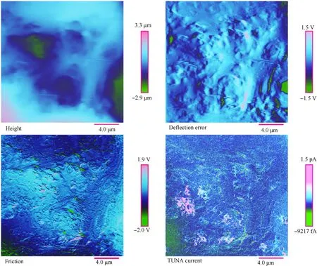
Fig. 4. TUNA images of the etched fraction surface of the multifunctional resin.
The images clearly evidence that CNTs are well distributed in the sample.For our aim,the most relevant image is that corresponding to the TUNA current.It is well evident,for the same color tone,well diffused in the frame of the image, that the sample shows almost the same electrical conductivity throughout the surface.In fact,the blue color dominates in a diffused way on the whole image. The network of nanotube filaments (of lighter blue color) results well organized through the sample and seems perfectly interpenetrated in the hosting polymeric matrix to give it an electrical conductivity corresponding to the same color tone over large areas.
It is worth noting that the cured multifunctional epoxy mixture also manifests a high value of the glass transition temperature(Tg).In fact,the value ofTg,determined by DMA,was found to be 247◦C,a value very similar to that obtained for epoxy resins based on the tetrafunctional epoxy precursor (TGMA) loaded with CNTs and using only DDS as a hardener agent [40].
Furthermore, considering that under accidental aircraft fire conditions, the most vulnerable part of a panel is the epoxy resin between the carbon fiber layers, the LOI value of the solidified multifunctional epoxy resin was determined according to the standard mentioned in Section 2.1. The multifunctional resin used for the manufacturing of Panel LS1 is characterized by a value of LOI(%)value of 36(with respect to the value of 27 corresponding to the resin without flame retardants), and the maximum degradation temperature was found to be 414◦C.
Being the results obtained for the multifunctional resin suitable for manufacturing load-bearing composites, panels manufactured according to the procedure described in section 2.1 were prepared.The electrical properties of the obtained panel were investigated using the same investigation applied for the multifunctional resins.
The in-plane DC conductivity of the panel was found to be 1.39 × 10⁴S/m. This value is in line with the values of electrical conductivity already found for CFRCs containing 0.5% of MWCNTs and only GPOSS as flame resistant component(5 wt%) [7].
TUNA images of the LS1 panel strips are shown in Fig. 5.
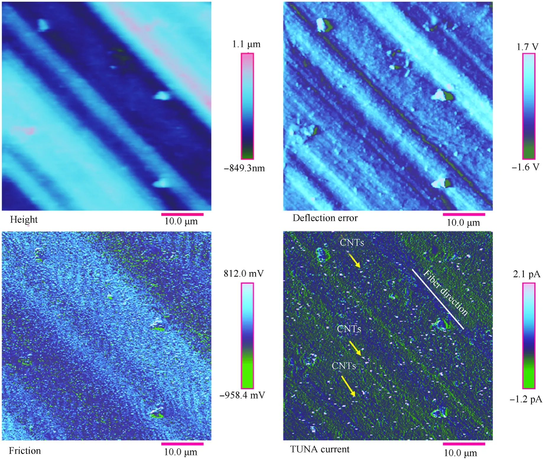
Fig. 5. TUNA images of the etched string of the LS1 panel.

Fig. 6. TUNA images at higher magnification of the etched string of the LS1 panel.
It is worth noting that,as described in the experimental section,the samples were chemically etched before the morphological investigation, then a part of the resin were removed before the observation.
This allows to better observe the CNTs filament and the carbon fiber direction. From a comparison of the TUNA image with the other three images, it is well evident that the carbon fibers (see white segment in Fig. 5) of the woven constitute the most conductive part of the sample surface (blue tone in the TUNA image). In light of the relevant difference detected in the electrical conductivity of the multifunctional resin and the panel strips, this last result was expected. However, despite the etching procedure,the resin well adheres to the carbon fibers, and carbon nanotubes can be seen in all parts of the image (both the most and less conductive regions), see yellow arrows in Fig. 5. TUNA images at higher magnification in Fig.6 clearly allow differentiating between CNTs and CFs. The color scale evidences that CFs and CNTs appear with of a lighter color tone. Nevertheless, the nanofiller is well interpenetrated in the matrix among CFs,as such to confer almost the same tone of color to the whole image and corresponding to an electrically conductive matrix.
To better understand the distribution of the carbon nanotubes among the fibers of the carbon woven,HRSEM images of the panel after a strong etching procedure have been collected. Despite the strong chemical etching, it has been found that many carbon nanotubes form a tightly bonded network to carbon fibers. Fig. 7 shows that the strong etching consumes almost completely the resin in contact with the fiber and the carbon nanotubes, but the CNTs in the resin in contact with the fiber are not completely removed as they are well interpenetrated between the fibers and adhered to them.
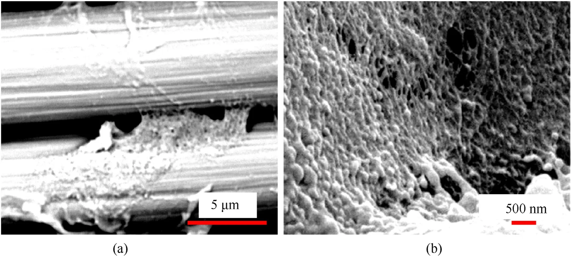
Fig. 7. HRSEM images of the carbon panel: (a) region near to the carbon fibers; (b) magnification of a region between CFs.
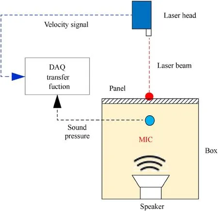
Fig. 8. Laser vibrometry test set-up.
3.3. Laser scanning vibrometry test
The laser vibrometry test allows measurements of the modal properties of a structure avoiding any contact with the examined surface using an external dynamic load; in this case, an acoustic pressure emitted by a sound source has been applied.The reference panel was installed as a cover of a soundproof box with a sound wave generator on its bottom side:the transfer functions between the acoustic signal measured by a microphone inside the chamber and the surface vibration velocity detected externally by the laser head were measured in the range(20, 4000 Hz); general set-up is reported in Fig.8.The frequency response(vibration velocity/input pressure level) includes a series of peaks (Fig. 9) representing a measure of the modal vibrations and the relevant mode shape.Specifically, relying on these amplitude peaks the significant damping coefficients could be evaluated.Except the initial zone of the spectrum where some high peaks occur mainly related to a rigid plunge motion of the panel,other resonances indicative of the elastic deformation are measured between 50 and 350 Hz, Fig.10.
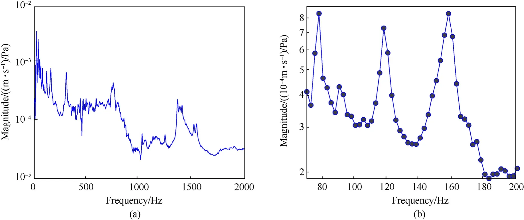
Fig. 9. Laser vibrometry results: FRF between surface vibration and acoustic pressure: (a) Broad spectrum analysis; (b) Spectral windowing of modal region.
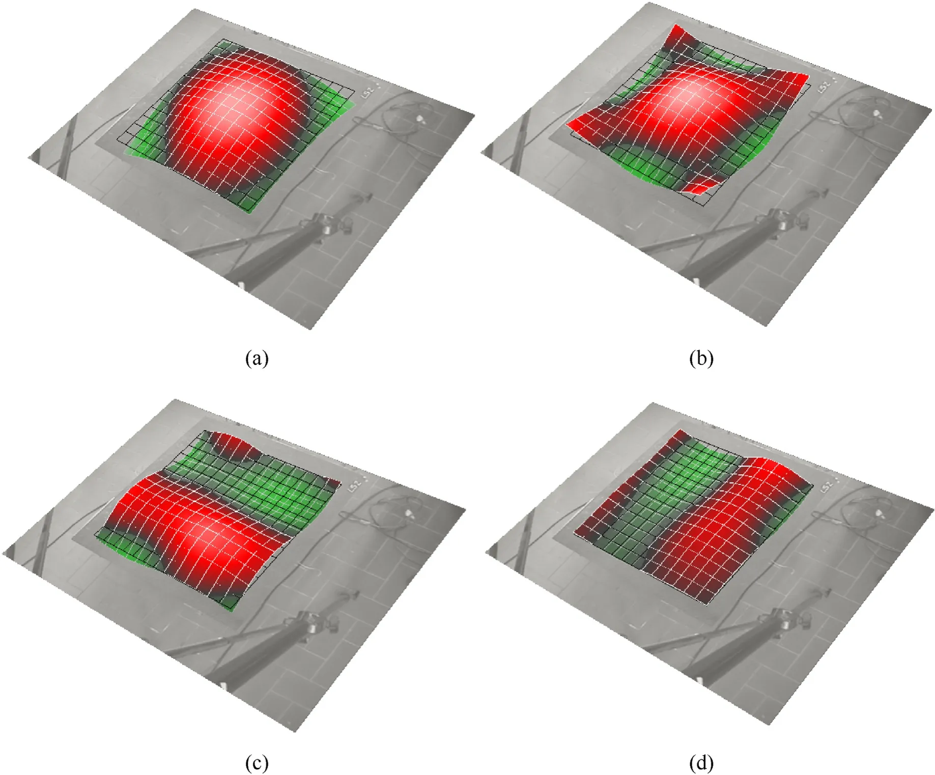
Fig. 10. Operating Deflection Shapes: (a) Tympanum mode shape, f = 78 Hz; (b) Symmetric bending mode shape, f = 120 Hz; (c) First anti-symmetric bending mode shape,f = 158 Hz; (d) Second anti-symmetric bending mode shape, f = 158 Hz.
The damping measurement performed by the Half Power Bandwidth method is of course a way to quantify the dissipative properties of a structural component,in the frequency range where normal modes (and/or their combination) affect the dynamic behaviour. Such energetic method considers the amplitude peaks of interest and the two respective spectral limits (φ2and φ1) corresponding to a drop from the resonance maximum of 3 dB(equivalent to the root mean square Ieff,Ieff=Amax/√2)according to the following Eq. (1).
The results achieved through the previous method are tabulated and diagrammed in Fig.11, with special reference to the first four modes,as reported in Fig.11:mode(1,1)in the form of tympanic or free edge bending mode and mode (1,2)/(2,1) in the form of first order(i,j)flexural modes;these last two,corresponding to the same frequency because of the symmetric shape of the panel. An increment of almost twice the damping measured on a conventional composition was observed following the addition of carbon nanotubes inside the former resin.
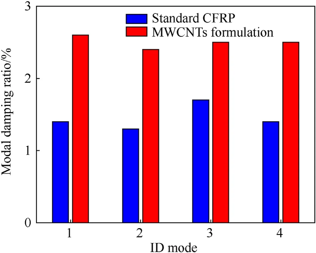
Fig.11. Damping ratio for each of four mode shapes.
These results can be explained in light of the interfacial contact friction between CNTs and polymer resins and among the nanotubes themselves (micro stick-slip) [41]. Generally, the material dissipating properties depend on the structural strain,CNTs volume fraction,interfacial bonding strength and the critical shear stresses at which slippage occurs[42,43].A second aspect to be considered is the modification of the polymeric matrix due to the introduction of the filler, in fact in previous work in which an epoxy resin was modified with the introduction of carbon nanotubes, a change in the mechanical properties was found [44]. Dynamic mechanical analysis(DMA)evidenced that the samples containing CNTs exhibit two falls in the storage modulus and two peaks in the tanδ of which one at lower temperature with respect to the main peak related to the main glass transition temperature of the epoxy matrix[45].The authors ascribed the second peak (at lower temperature and intensity) to the presence of an additional phase with a different(lower) crosslinking density. This hypothesis is plausible considering that the presence of the CNTs interrupts the cross-linking points in the regions of the sample where CNTs are placed. Of course,the phase at lower crosslinking density is most likely placed close to the wall of carbon nanotubes.Hence,the matrix in contact with CNTs is characterized by lower glass transition temperature and is more deformable with respect to the parts of the matrix not in direct contact with CNTs. This higher flexibility of the chain segments increases the damping capability of the epoxy matrix.Then,the increase in the damping properties due to the interfacial friction between the nanofiller and the polymeric matrices,already found by other authors[42,43,46—48]is affected in a synergic way by the higher deformability of the epoxy matrix around the CNTs.
3.4. Acoustic performance: transmission loss assessment
The experimental study has also been focused on the characterization of sound insulating capacities of the CNTs based panel in terms of transmission loss (TL, dB), referred as the logarithmic difference(using the dB scale)between the incident acoustic powerwiand the passing acoustic powerwtEq. (2)
Due to the specific test setup, the measurement has been performed according to the UNI EN ISO 15186-1 standard procedure[49]. This procedure implies the measurement of sound pressure level (here realized by the use of omnidirectional microphones)inside the box and sound intensity level(here realized by the use of a pressure-pressure intensity probe)outside the box(immediately downstream the panel), as illustrated in Fig.12.
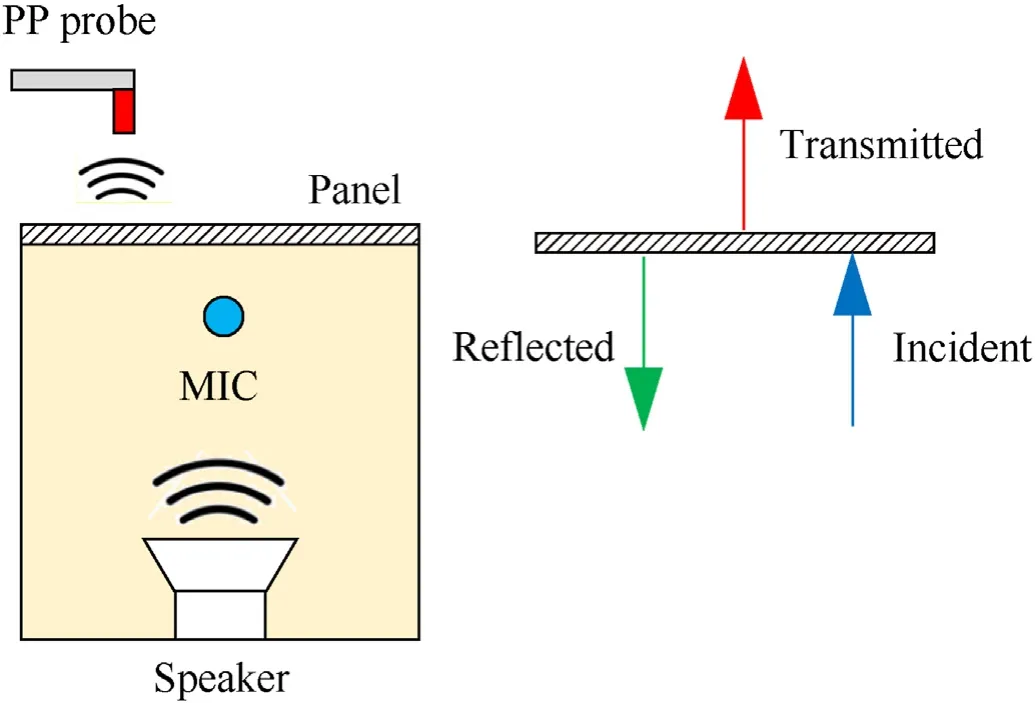
Fig.12. Sound power transmission measurement setup (left) acoustic energy balance(right).
The average sound intensity was measured as follows Eq. (3):
Using the incident SPL (measured by the microphone in the closed room)and the Sound Intensity(externally detected), theTL(or equivalently the sound insulationRi) is given by Eq. (4)
where:
•Lpis the average sound pressure level inside the reverberating box;
•Linis the average sound intensity level;
•Smis the measuring grid total area;
•Sis the partition total area.
The measured sound insulation diagram is reported in Fig.13.Three main physical regions could be observed. The first range,where the static stiffness dependency is prevailing (the structure exhibits less capability to dissipate acoustic energy when frequency increases and then with lower modal displacements),explains the descending profile of theTLcurve generally described by a firstorder law. The second part of the graph is controlled by the normal modes participation before passing to the mass-law governed third part of the diagram.

Fig.13. Sound insulation power trend as function of frequency.
The comparison ofTLdiagrams related to a “reference” CRFP panel and the functionalized CNTs test article show an increment of the noise reduction comprised between 6 and 8 dB compatible with theoretical evaluation,as a consequence of the increased structural damping as previously measured (paragraph 3.2) that drive to an equivalent increment of the structural loss factor[50,51].
4. Conclusions
The current industrial scenario, especially in the transport sector,pushes towards ever-lighter design choices and at the same time with outstanding structural and functional performance. The goal of incorporating several functionalities into a single material has therefore become the challenge of many research groups. In such perspective, composite materials certainly offer more possibilities to manipulate their respective physic-chemical properties in view of the requirements to be achieved.
In the present work the following activities have been performed:
(1) Carbon fiber reinforced panel has been manufactured with the aim to contrast electrical insulating property and poor flame resistance of the epoxy resins impregnating carbon woven;
(2) the electrical conductivity of the multifunctional resin and the manufactured panel have been measured. Both values were found satisfactory enough, being 4.02 × 10⁻²s/m and 1.39 × 10⁴s/m respectively;
(3) TUNA images demonstrated a good dispersion of the nanofiller in both the multifunctional resin and the panel manufactured by adopting a bulk infusion process;
(4) The solubilization of GPOSS in the resin and the replacement of a part of DDS(46.7%)with BAMPO allows for improving the flame resistance of the multifunctional resin (loi value increases from 27% to 36%);
(5) Considering these promising results, an experimental assessment of the vibro-acoustic characteristics of the manufactured multifunctional panel.The panel was tested to evaluate its low frequency vibration damping and sound insulation;
(6) The results, although preliminary, are very encouraging to investigate further aspects, especially regarding the mathematical modelling of these new properties;
(7) The proposed formulation has demonstrated an improved efficiency if compared to a baseline configuration,presenting about the double of modal damping and a gain of about 6 dB on the global noise reduction.
Funding
This research did not receive any specific grant from funding agencies in the public, commercial, or not-for-profit sectors.
Declaration of competing interest
The authors declare that they have no known competing financial interests or personal relationships that could have appeared to influence the work reported in this paper.
杂志排行

Defence Technology的其它文章
- A review on lightweight materials for defence applications: Present and future developments
- Study on the prediction and inverse prediction of detonation properties based on deep learning
- Research of detonation products of RDX/Al from the perspective of composition
- Anti-sintering behavior and combustion process of aluminum nano particles coated with PTFE: A molecular dynamics study
- Microstructural image based convolutional neural networks for efficient prediction of full-field stress maps in short fiber polymer composites
- Modeling the blast load induced by a close-in explosion considering cylindrical charge parameters