Operational feasibility study of stagnation pressure reaction control for a mid-caliber non-spinning projectile
2023-07-04Bouquet
F. Bouquet
The Netherlands Organisation for Applied Scientific Research, Oude Waalsdorperweg 63, 2597 AK Den Haag, the Netherlands
Keywords:Supersonic projectile Feasibility study Ram air Stagnation pressure reaction control Simulation Attitude control
ABSTRACT
1. Introduction
Precision of gun-launched projectiles is a key element in modern, high-precision military operation. A one-shot-one-kill capability can limit collateral damage, reduce required ammunition demand and increase endurance.Perturbations such as variation in manufacturing repeatability, projectile balloting, aiming errors,influence of wind and target manoeuvring will lead to a certain level of imprecision, or dispersion, that modern fire control computers will never be able to completely correct. Furthermore, it is never completely possible to predict the trajectory of a maneuvering target. This underlines the need for projectile control.Controlled,guided munitions can reduce the dispersion in the shot,while providing the capability of engaging maneuvering targets.
Projectiles can be controlled in flight using aerodynamic surfaces [1,2], or using other means. Such other, innovative means of control include articulation of the projectile body[3—5],controlling the boundary layer to induce differential drag [6—8], shifting internal mass [9—11], or generating impulse thrust perpendicular to the projectile axis [12—14]. This impulse thrust may be derived from small thrusters embedded in the projectile body,or from a gas plenum feeding ejection orifices. Another promising method for controlling the projectile orientation is using ram-air to asymmetrically modify the flow around a projectile and create pressure differences for control [15].
This study will examine the so-called 'Stagnation Pressure Reaction Control',or SPRC technology,in which high pressure air from the stagnation point of the projectile, also called 'ram air', is expelled through one of four ejection ports upon demand to provide desired control moments around the center of mass. (See Fig.1).
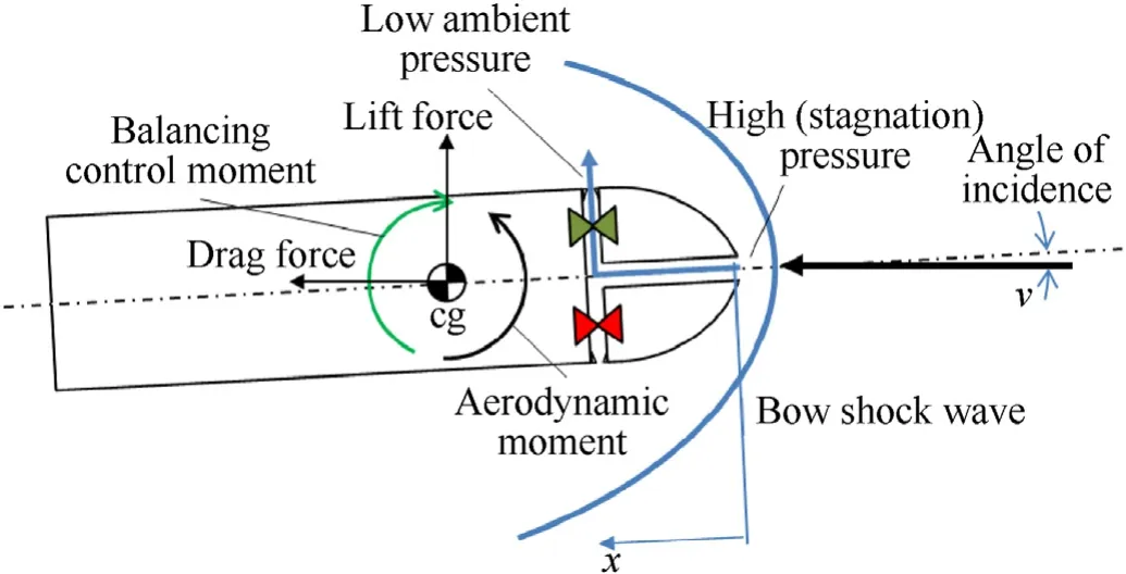
Fig.1. Working principle of SPRC showing how high pressure stagnation air is used for generating lateral control thrust from Ref. [16].
The primary advantage of this control method over conventional aerodynamic fin control is the lower radar signature and the ability to keep a full-caliber projectile without requiring technicallycomplex fin-unfolding mechanisms. TNO has been developing SPRC technology since 2016 and has demonstrated this technology in a Mach 2 wind tunnel experiment for an aerodynamically unstable projectile-like test object[16].The experiment demonstrated the potential of the SPRC technology, with carefully characterized latency and delays, combined with a suitable control algorithm to stabilize and control an aerodynamically unstable, non-spinning projectile-like test object to angles of incidence of up to 1.5◦. Angles of incidence of 0.5◦were achieved in a control response time of 30 ms.
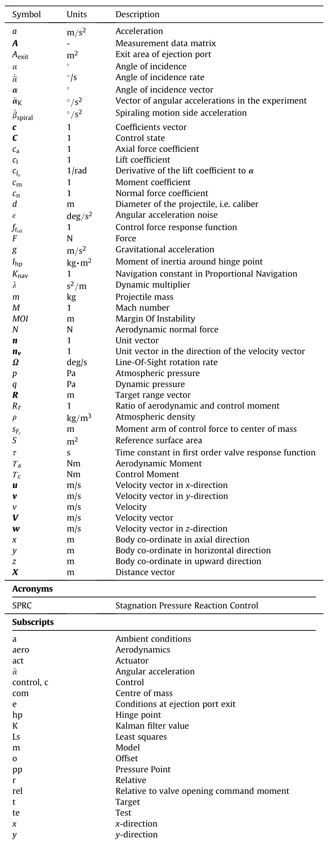
Nomenclature
In practice, a sudden change of wind speed of 20 m/s experienced during Mach 2 flight will increase the projectile angle of incidence by almost 2◦. This means that for a practical and operationally significant course-correcting projectile, stable and controllable angles of incidence are required that are significantly larger than 2◦throughout its mission from launch to impact on target.
An additional challenge is the gradual and continuing forward shift of the aerodynamic pressure point with decreasing Mach number.Due to this shift and the absence of spin,the decelerating projectile will become increasingly unstable during flight.Furthermore, the decelerating projectile will experience a decline in Mach number that not only reduces the stagnation pressure,but also reduces the overall pressure level over the projectile and therewith the pressure difference over the ejection ports. As the projectile is aerodynamically decelerated the control force steadily decreases during flight. The increasing instability and decline in control force will ultimately lead to a loss of controllability of the projectile in the lower subsonic region.
This work presents a feasibility study into the practical use of SPRC in a non-spinning 30 mm projectile.The aim of this study is to simulate, and thereby demonstrate that, when integrated in a projectile, SPRC technology would be able to stabilize and control the selected mid-caliber projectile configuration throughout its flight path, from launch to impact, in a direct fire mission, against stationary as well as maneuvering targets.For improved reliability of the result, this study uses the control performance data of the previously mentioned experiment [16] as input.
This work focuses on the supersonic portion of the flight path where the control force is sufficiently high to put the projectile under a desired angle of incidence. In the transonic and subsonic regions of the flight path, the SPRC projectile becomes more and more destabilized as described above. The low level of the control force in that region (see Fig. 10) requires a different approach in guidance using a spiraling motion of the projectile, tweaking the radius of the spiral to achieve trajectory modification.This different approach is however beyond the scope of the current article and will be addressed in future work.
To the best of our knowledge the assessment of the application of SPRC technology in a supersonic projectile has not been reported elsewhere.
This article is built-up as follows.Analyzing the behavior of the SPRC projectile during flight requires building blocks such as aerodynamic analysis, projectile lay-out and mass distribution,stability analysis and control behavior. Section 2 describes these building blocks and provides the theoretical background to this work. Section 3 explains the simulation setup used to determine the SPRC projectile trajectory and behavior. Section 4 presents the trajectory analysis results obtained for the selected projectile shape and mass lay-out. Section 5 summarizes the main findings of this work and presents recommendations for further work.
2. Projectile and control design
This work aims to quantify the performance of a projectile using SPRC technology for control. This quantification requires a projectile design including i)inertial characteristics,ii)external shape and aerodynamic characteristics, iii) control behavior under varying Mach numbers.The following paragraphs explain key aspects of the above topics.
2.1. Projectile shape
The mid-caliber projectile shape used in the wind tunnel experiments [16] was highly unstable, leading to relatively small maximum stable angles of incidence up to 1.5◦at Mach 2. In the current work the challenge was to design a projectile shape with a lower margin of instability,or MOI(i.e.making the projectile more stable). The MOI is defined by the distance between the center of pressure and the center of mass of the projectile (see Fig.1).
A decrease of the MOI can be obtained by either i) shifting the pressure point aft, or ii) shifting the center of mass forward. A pressure point shift may be obtained by modification of the external shape of the projectile, having an effect on local pressure and, hence, on the total resulting moment of these pressures around the center of mass. A shift of the center of mass may be obtained by internal rearrangement of subsystems, adding mass/high density volume in the nose.
Several shapes were analyzed for their location of center of pressure in relation to the center of mass.The challenge was to shift the center of pressure as far aft as possible, without having to introduce fins that would extend beyond the projectile caliber.Fig. 2 shows a sketch of the resulting shape. This shape features a nose section,followed by a narrow section with eight small strakes.The strakes end in a flare that extends back to the projectile caliber.The back end flare helps to shift the center of pressure backwards towards the center of mass,decreasing the level of instability of this hypothetical projectile.The total length of this projectile is 115 mm with a caliber of 30 mm.
2.2. Aerodynamic characteristics
Aerodynamic characteristics were determined using MISL3[17]treating the strakes as small-span fins with aspect ratio and taper within the allowable applicability limits of MISL3 [17]. This aerodynamics code has shown to produce reliable aerodynamic trends[18]for missile-and projectile-like configurations for use in design study phases. Fig. 1 of Ref. [18] shows the use case that best resembles the current study. This figure indicates that at Mach 3.11,MISL3 underestimates the axial force coefficient by 22%. It is also acknowledged that there will be an effect of the frontal air intake and the four exit holes on the overall projectile aerodynamics,especially the drag coefficient. The lateral jets will slightly change the pressure distribution on the projectile front that will become noticeable as additional drag through the sine of the local inclination of the projectile’s outer surface.MISL3 did not allow studying this effect. This means the drag coefficient will be more underestimated than the aforementioned 22%.This means that an actual projectile would decelerate faster, decreasing its effective range.Furthermore Fig.1 of Ref.[18]shows that MISL3 overestimates the experimentally derived aerodynamic characteristics for that use case by an amount between 0 and 20% for the normal force coefficient between 0 and 5◦angle of incidence. This means that any maneuver would require a slightly higher angle of incidence. The non-dimensionalized stability margin (xcp-xcom)/d, in Fig. 1 of Ref. [18], is 13% lower than experimental values at 5◦angle of incidence.This means that in reality,the projectile is expected to be more stable than estimated using MISL3. The fly-out simulations based on the MISL3 results are therefore considered to be worst case in terms of required control forces and best case in terms of range, although further projectile shape optimization may reduce the drag coefficient.
Based on the previous considerations the aerodynamic characteristics provided by MISL3 are deemed sufficiently detailed for the purpose of simulating the ability of SPRC to steer a hypothetical projectile to its assumed target.Expected errors in the current flyout simulation results will be indicated where appropriate.
Fig. 3 shows the lift coefficient as a function of the angle of incidence for different Mach numbers. Due to the absence of a significant wing section,a projectile-like object will have a low lift coefficient and,hence a low lift to drag ratio.Fig.4 shows the drag coefficient as a function of Mach number and angle of incidence.The low lift to drag ratio leads to low levels of induced drag,visible by the modest dependency of the drag coefficient on the angle of incidence.
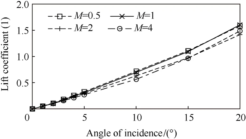
Fig. 3. MISL3 supersonic lift coefficient as a function of angle of incidence for Mach = [0.5, 4].
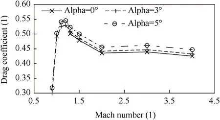
Fig. 4. MISL3 supersonic drag coefficient for alpha = [0, 5].
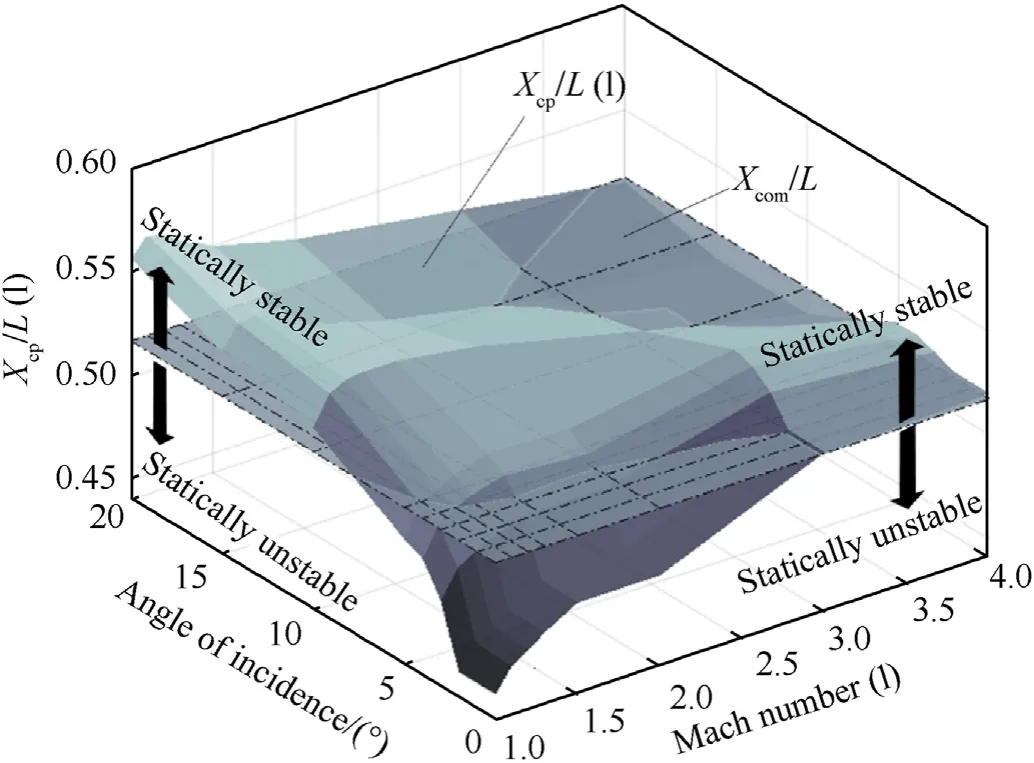
Fig.5. The location of the center of pressure is Mach dependent and shifts forward in flight, as aerodynamic drag reduces the velocity.
The center of pressure changes with Mach number and angle of incidence impacting the controllability of the projectile considered here.The projectile shape and internal lay-out were chosen to have a stable flight configuration at high supersonic Mach numbers(M> 3), allowing the center of pressure to shift forward during flight, destabilizing the projectile.
Fig. 5 shows the behavior of the center of pressure of the projectile with Mach number and angle of incidence.The figure shows that the projectile is fully stable above Mach 3 up to 5◦angle of incidence.At intermediate and low Mach numbers,the projectile is unstable at zero angle of incidence, but shows stable behavior at higher angles of incidence. It will therefore naturally stabilize at non-zero angles of incidence. In the unstable region, the control force must stabilize and control the projectile whilst being able to absorb disturbances such as gusts, that increase the angle of incidence.
2.3. Center of mass
For this shape,the high-level internal lay-out was determined to obtain an estimate of the location of the center of mass. As a projectile is a thick-walled metal shape with lower density internal systems and materials the center of mass is mostly dependent on external shape. The center of mass of the current, hypothetical projectile was determined to be 60 mm downstream of the nose.
2.4. Derivation of experimental control force benchmark
The realized SPRC performance was deduced from the experimental data obtained in a wind tunnel experiment[16].The use of regression techniques on the measurement data allowed the creation of a model of the control force exerted on the test object during the experiment.This experiment-derived control force was used in the fly-out simulations of the hypothetical projectile assumed in the current study,allowing these simulations to remain close to reality in terms of angular response.The experiment that is referenced used a cone-cylinder-flare configuration with SPRC ejection ports placed 10 mm from the frontal stagnation air inlet(See Fig. 6). The test object was hinged aft of the location of the center of pressure providing aerodynamically unstable test object behavior that allowed demonstration of the SPRC technology to keep this test object stable and controlled under Mach 2 conditions.

Fig. 6. The SPRC wind tunnel demonstrator model showing the 120 mm long, flared projectile shape, suspended in its centre of mass, with one rotational degree of freedom allowing it to rotate in the vertical plane, from Ref. [16], reprinted with permission.
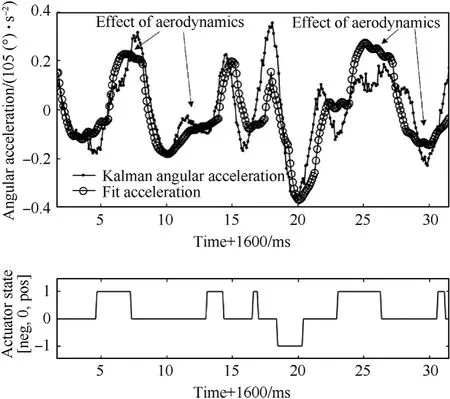
Fig.7. Derived Kalman angular acceleration,Kalman angle,actuator state and derived least squares solution of the angular acceleration in the wind tunnel experiment.
In the experiment (denoted by subscript te) the object was subjected to aerodynamic forces, control forces and other, noiserelated sources, such as mechanical vibrations and flow turbulence. This results in three contributions to the object’s angular acceleration.
The concurrent acting of these three contributions makes it impossible to deduce control-related acceleration levels from the measurement data in a direct manner.Instead, a regression model was constructed to distinguish between the control- and aerodynamic contributions.
In the experiment, the angle of incidence was measured using an eddy current sensor. Kalman filtering of these measurement data[16]allowed the angular rate,required for the selected control algorithm,to be derived while suppressing the amplification of the sensor noise that is involved in the differentiation of the eddy current signal. This Kalman angular rate was differentiated a second time to obtain a measure of the test object’s angular acceleration. This angular acceleration consists of the 'real' angular acceleration of the test object(¨αte)and an unspecified level of noise(ε) introduced by the differentiation of the measured angular rate signal.
This angular acceleration will have a time-offset with respect to the test object’s actual acceleration,as indicated by thet0term,due to the Kalman filtering of the original angle-signal. To find the control forces from the Kalman angular acceleration, a behavioral model (subscript 'm') of the angular acceleration is hypothesized,containing control- and aerodynamics contributions:
In this equation,ccis the unknown control force coefficient andCis the control state, which was recorded during the experiment.
Functionftrelis a dynamic, first order response function of the control force that indicates the time dependent rise of the control force and reflects the associated response time from the moment the valve command is given.
The time required for the actuation system to open the actuation port is modelled using a first order transfer function.wheret0actis the time of ejection port opening command.The time constant in this first-order response curve has been based on visual inspection of the angular acceleration data from the experiment and is equal to
The coefficientscai,i=[1…3]in Eq.(4)are unknown coefficients pertaining to the aerodynamic contribution to the angular acceleration. The aerodynamic contribution is assumed to be quadratic and destabilizing. This means that the occurrence of a non-zero angle of incidence will tend to further increase the magnitude of this angle of incidence. The constantca1includes the effect of any asymmetry of the projectile’s aerodynamics.
To be able to derive the contribution of the control force to the angular acceleration, it is hypothesized that there exists a set of coefficients,c,for Eq.(4)that will minimize the difference between the model and the Kalman acceleration derived from the measurements(¨αK).In vector notation,this hypothesis is formulated as follows:
With A the matrix containing the control state and angular measurement data at all measurement times. This is a linear system that can be easily solved in a least squares (subscript 'ls') method,for the coefficients vector c
Fig. 7 shows the Kalman angular acceleration and the least squares solution of the angular acceleration (the 'fit acceleration'),together with the actuator state from the experiment. The figure clearly shows the effect of the valve openings on the resulting projectile acceleration. The slope of the acceleration in between valve changes, after the transient effect of valve closing (as indicated by the arrows) shows the effect of aerodynamics on the acceleration.
The temporal offset(to,Eq.(3))introduced by the Kalman filter,was found by minimizing the least squares error as a function of this offset. The value of the temporal offset was found to beto=1 ms. The figure shows reasonable agreement between the least squares solution and the Kalman angular acceleration. The remaining error is attributed to the aforementioned sources of error, such as measurement noise, hinge characteristics, etc., that have not been modelled explicitly.
The least squares solution allows the distinction between the control accelerations and the aerodynamic accelerations from Eq.(4).
From this result, the maximum control force can be estimated using the moment of inertia of the test object around its hinge point(Ihp)and the distance of the ejection port from this hinge point(sc):
This analysis yields a control force of 1.25 N during the wind tunnel experiment at Mach 2 and a total pressure equal to 3 bar.
2.5. Control force behavior
To translate the experimental control force to flight control forces for a fired projectile, it is noted that for a given design at a given Mach number the control force scales with total pressure behind the shock wave.The wind tunnel experiments of[16]were carried out at a storage (total) pressure equal to 3 bar at Mach 2.Behind the shock wave, this resulted in a total pressure equal to 2.16 bar. When travelling in the standard atmosphere at Mach 2 conditions at sea level,the total pressure in the free stream is equal to 7.93 bar,yielding a stagnation pressure equal to 5.72 bar behind the shock wave.The ratio of total pressures behind the shockwave during experiments and in real flight would thus be 5˙72/2˙16 =2˙65.This means that the 1.25 N SPRC experiment-derived control force scales to 1.25 × 2.65 = 3.3 N at Mach 2 sea level flight conditions. In comparison, at 1◦angle of incidence, the projectile experiences a normal force equal to approximately 10 N at these conditions. In a stable configuration, the control force adds to the side force. In an unstable configuration, the control force diminishes the side force, reducing the normal projectile acceleration.
The effect of Mach number on the expected control force in the wind tunnel experiment was determined numerically using the High Mach Number Flow interface of Comsol Multiphysics® [19]using a free tetrahedral mesh in a section one-eighth of the test object’s conical nose section. This physics interface solves for conservation of energy, mass, and momentum, including turbulence effects that are described by the κ-ε model[20].This model assumes wall functions to solve for the flow conditions near the wall. For illustration purposes, Fig. 8 shows the pressure distribution on one-eighth of the test object’s conical nose section along with streamlines that indicate the interaction between the lateral jet emanating from the ejection port. This is visible by the rapid merging of the lateral flow with the main flow along the nose cone.
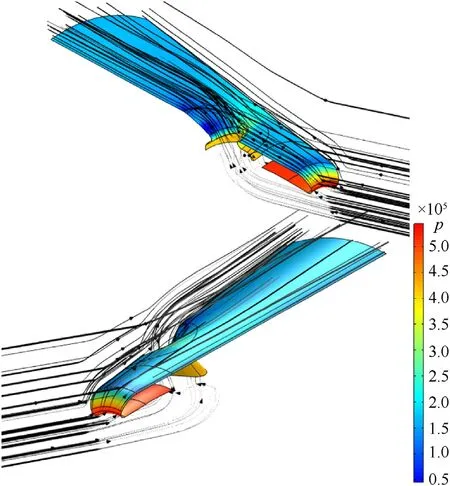
Fig. 8. Pressure distribution on one eighth of the test object wall and streamlines in Mach 2 flow from COMSOL CFD analysis.
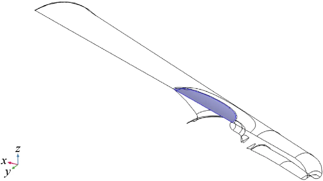
Fig.9. Thrust was determined by integrating impulse and pressure difference with the environment over the ejection port exit area.
The control thrust was obtained by integrating the impulse in upward direction and the pressure difference at the exit area,indicated in blue in Fig. 9 and the local ambient pressure.
Fig. 10 shows the thrust thus obtained as a function of Mach number. This figure shows that Comsol underpredicts the experiment-derived value. In the experiment the CFD-derived trend of thrust vs. Mach number was scaled using the experimental data point for Mach 2 conditions translated to flight conditions, as indicated in Fig.10.

Fig. 10. Control force as a function of Mach number. The circular markers show numerical data obtained using Comsol Multiphysics®, the triangle shows experimental data from Ref. [16] translated to sea level flight conditions.
The projectile-like test object of the experiment[16]featured a conical nose.The current hypothetical projectile features an ogival forebody for reduced aerodynamic drag. The smaller local surface inclination with respect to the body axis at the location of the ejection ports leads to a lower backpressure at the exit of the ejection ports and hence, a slightly higher thrust in the current study. However, to prevent the fly-out simulation results of the current study to be overly optimistic the experimentally derived thrust with scaled Mach-dependency has been used in the fly-out simulations described hereafter.
2.6. Static stability and controllability
The static stability of the projectile is indicated by a negative derivative of the aerodynamic moment (Τa) with the angle of incidence:
A positive derivative of the aerodynamic moment means that an increase in angle of incidence tends to reinforce this increase. A negative derivative tends to counteract the increase in angle of incidence and hence, leads to statically stable behavior. In the current work, the aerodynamic moment, Τahas been calculated using the aerodynamic normal force(N),multiplied by the margin of instability as defined in Eq. (1).
Note that this value is positive for unstable projectile behavior and is a function of Mach number and angle of incidence (see Fig. 5). For a controlled projectile the control moment is given by the control force (which is a function of the Mach number),multiplied by the distance of the control ejection ports to the center of mass.
Note that the values of the control moment and the aerodynamic moment need to be opposite in sign to impose an angle of incidence on the projectile in a static situation for stable as well as unstable projectile behavior.The ratio of the aerodynamic moment and the control moment(RΤ(M,α) =Τa/Τc<0),together with the aerodynamic moment derivative with angle of incidence indicate the state of stability and controllabilityS(M,α)of the projectile.For this variable, four distinct situations are recognized.
When the aerodynamic moment exceeds the maximum control moment in absolute value, the control system will be unable to bring the projectile to that combination of Mach number and angle of incidence,both for stable and unstable projectile behavior.Those regions are therefore 'inaccessible'. When the control moment exceeds the aerodynamic moment in magnitude, the control system will be able to control the projectile to a desired angle of incidence in that region. In these situations, the projectile is'controlled'. Fig. 11 shows these four regions ofstability and controllabilityas a function of Mach number and angle of incidence.

Fig. 11. The aerodynamic, inertial and control characteristics lead to regions in the Mach/α plane with different stability and controllability properties, described by S(M,α) in Eq. (16).
The two grey areas represent theaccessible angles of incidenceas a function of Mach number. The white (4) and black (1) regions represent theinaccessible angles of incidenceas a function of Mach number. In a dynamic situation the projectile may access the inaccessible black and white areas, but in both these areas the aerodynamic moment will push the projectile back to the light or dark grey area. The boundary between the unstable and stable controlled areas (Region 2 and Region 3) signifies the non-zero stable angles of incidence that exist below Mach 3 (see also Fig.5).The existence of non-zero stable angles of incidence can be explained from the destabilizing lift force generated by the ogive nose, which is nearly constant with angle of incidence, and by the stabilizing lift force from the strakes that show a stronger dependency of lift with angle of incidence.For instance,at Mach 2,the stable angle of incidence is found to be approximately 4◦.Without active control the projectile will assume this angle of incidence and deviate off its intended flight path.
The figure shows that the current projectile shape leads to a substantial improvement of the stable angle of incidence of 1.5◦in the projectile-like shape used in the experiments[16]to at least 6◦,as indicated by the light grey area in the intermediate Mach numbers.
2.7. Proportional Navigation and trajectory integration
There are several methods to guide a projectile to the target,using either active or semi-active seekers [21,22,24] and a Proportional Navigation algorithm.A beam-riding concept[23]provides a more low-cost alternative where the projectile has a passive sensor in the back for guidance,with the targeting and logic provided by a ground-based unit. In this work, the trajectory of the hypothetical projectile is integrated in three-dimensions, assuming a Proportional Navigation guidance algorithm. In Proportional Navigation,steering commands are proportional to the line of sight rate between projectile and target. For this analysis, the projectile is assumed to have a means of sensing the direction of the target,for instance using a semi-active laser solution.The relative velocityVrand rangeRare defined as
where Vtand Xtare the target’s velocity and position,respectively.The Line-Of-Sight rotation rate is defined as
Proportional Navigation defines the acceleration required to achieve target hit.
To achieve the required acceleration,the projectile will need to assume a required angle of incidence that is obtained by integrating its derivative, as defined by
where τ is the desired time constant of the control loop, nvis the unit vector in the direction of the velocity vector and λ is a dynamic multiplier, given by
wheremis the momentary mass,qis the dynamic pressure,Sis the reference surface andclαis the derivative of clto α.
3. Simulation setup
The projectile’s kinematic behavior was modelled using Matlab/Simulink® allowing simulation of the projectile’s trajectory.
3.1. Objective
The simulations aim to provide a theoretical proof-of-concept for using SPRC as a fin-less control technology in a gun-launched,supersonic projectile, by showing that the current shape and related aerodynamics,combined with the SPRC technology,is able to bring the projectile to a stationary and a moving target while under supersonic flight conditions. The simulations assume a reliable measurement of the LOS to the target and a measurement of angle of incidence to be available. The simulations furthermore assume zero roll.In reality,after having been fired from a smoothbore gun some residual roll may remain which may be sensed by for instance a tail optical cell with a ground-based illuminator.This can be combined with for instance the previously referenced semiactive laser guidance option [21,22,24], with projectile illuminator[25].Otherwise a beam-riding guidance option[23]can provide the projectile with the required roll reference although this option will require a different guidance scheme than the PN scheme assumed in the current work.
3.2. Engagement conditions
In the current simulations,launch velocity has been assumed to be 1000 m/s against a 1500 m range stationary and maneuvering target. At this target range, dispersion in the shot may be limited,while target maneuvering will present the largest need for projectile controllability. Longer range targets are well within the operational envelope of most 30 mm projectiles. However, the 1500 m range has been chosen to present the supersonic flight behavior of the current projectile. With this initial set of engagement parameters thebasic functionalityof the projectile with control characteristics as determined from experiments [16] is theoretically demonstrated in the projectile’s supersonic flight regime. Behavior of this projectile in the trans- and subsonic regions is identified as the immediate next step in this analysis,but is beyond the scope of the current article.
In all shown simulations the projectile is assumed to be fired directly at the target with no trajectory elevation to correct for gravitational pull.Furthermore,the projectile is assumed to be fired with zero total angle of incidence and zero total angular rate. In reality,perturbations on these values may exist that will affect the flight path.At this moment however,this is considered to be within the capability of the control system and is not analyzed further.
3.3. Simulation components
Fig.12 shows a schematic of the simulation which models the behavior of the projectile taking Initial Conditions and a Target Trajectory as input.
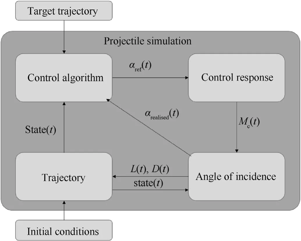
Fig.12. The simulation encompassed the kinematic behavior of the projectile as well as detailed angle of incidence control as established experimentally in Ref. [16].
The“Trajectory”block integrates the equations of motion of the projectile assuming it to be a point mass with three spatial and two rotational degrees of freedom, under the assumption of zero roll.The reference angle of incidence is determined by the “Control Algorithm”, based on the projectile state and the target location.The reference angle of incidence is followed by the “Control Response” block, which is a representation of the mechanical response of the SPRC control technology and the achieved control moment,as established experimentally in Ref.[16],and quantified in Section II. The control moment and aerodynamic moment determine the projectile’s angular acceleration, rate and angle of incidence, as determined in “Angle of Incidence”.
3.4. Control scheme and response
The control response is characterized by the reaction time of the control valve,which has an opening and closing time of 600 μs with a maximum repetition frequency equal to 400 Hz.The control loop has an update frequency of 16 kHz.The control algorithm deciding the opening and closing of the valves is covered in Ref.[16].This is the bang-bang control with tunable decision planes. This is a control scheme based on the error in angle of incidence and its first time-derivative, where the error is defined as the difference between the actual angle of incidence, αrealised(t) and the desired angle of incidence,αref(t).Fig.13 shows the decision scheme in the error and error derivative plane. The grey areas indicate where either the plus or minus valve are opened.With four control valves,the projectile contains two such sets of opposing valves. Between these grey areas the valves are not opened. The direction of these'tunable decision planes'are variable and can be selected such that the error between commanded and realized angle is minimized.This simulation allows the performance of SPRC in the given projectile platform to be studied in detail.
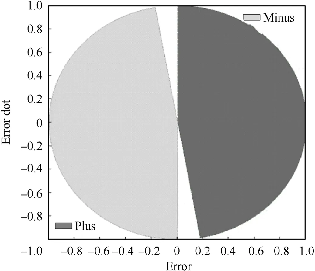
Fig.13. The control algorithm uses the error in alpha and the rate of error to determine the on-off control commands, in a scheme called 'bang-bang control with tunable decision planes'.
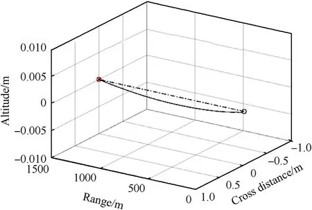
Fig. 14. 3D Trajectory, 1000 m/s muzzle velocity, 1500 m range, zero target cross velocity.
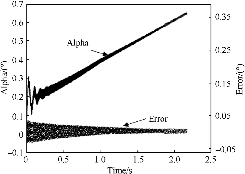
Fig. 15. Realized angle of incidence and error with respect to commanded angle of incidence,1000 m/s muzzle velocity,1500 m range, zero target cross velocity.
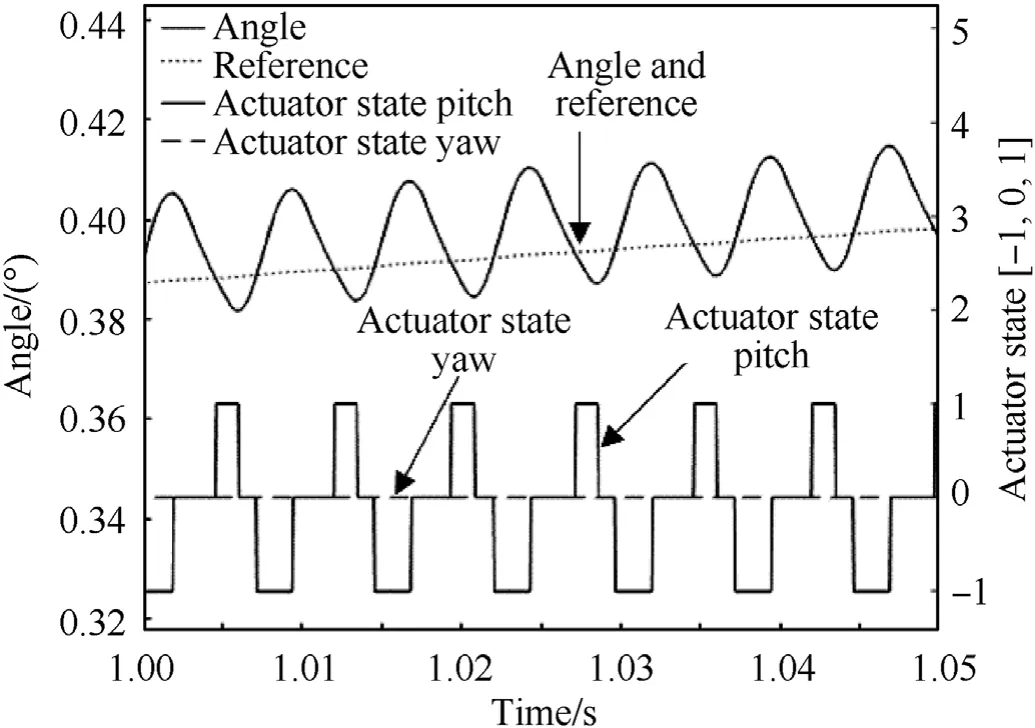
Fig. 16. Detail of realized angle of incidence, commanded angle of incidence, and associated actuator states,1000 m/s muzzle velocity,1500 m range, zero target cross velocity.
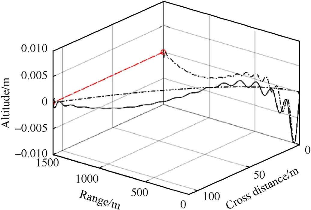
Fig. 17. 3D Trajectory, 1000 m/s muzzle velocity, 1500 m range, 50 m/s target cross velocity.
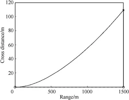
Fig. 18. Trajectory top view, 1000 m/s muzzle velocity, 1500 m range, 50 m/s target cross velocity.
In the simulation, the projectile’s yaw and pitch angles are controlled by two orthogonal control systems. The yaw control system operates the left and right ejection ports, while the pitch control operates the top and bottom ejection ports (Fig. 2).
4. Results
The following sections present the results of the SPRC projectile trajectory simulations, illustrating the feasibility of the SPRC projectile concept.
4.1. 1500 m range, zero target cross velocity
The first use case that is presented in this work engages a stationary target at 1500 m range to theoretically demonstrate basic functionality of the SPRC projectile. This is a straightforward scenario in which the projectile does not need to achieve any lateral course corrections and remains outside of the inaccessible region.Fig.14 shows the flight path for this scenario.The dash-dot line in the figure represents the horizontal path from launch point to target. The figure shows different scales on the three orthogonal axes.The vertical axis has a range from-10 to 10 cm,enabling the 1.5 cm vertical displacement of the projectile throughout the 1500 m flight. After a flight time of 2.17 s, the SPRC projectile hits the stationary target at a velocity of 510 m/s.
Fig.15 shows the realized angle of incidence and the error, i.e.the deviation from the commanded angle of incidence. The figure shows that in this simple scenario the SPRC control with a bangbang control with tunable decision planes, combined with a PN guidance scheme, keeps the projectile on the intended flight path throughout the complete flight, with errors well within [-0.05,0.05] degrees. The increase in angle of incidence balances the decline in dynamic pressure that is associated with projectile deceleration.
Fig.16 shows a detail of the time sequence with the commanded and realized angle of incidence and the associated actuator states.This actuator state indicates the activation of the angle increasing actuators(+1)or angle decreasing(-1)actuators.As expected the yawing actuator is idle in this scenario because of the zero target cross velocity.The plot shows the response time of the actuators.A cycle of positive and negative actuation, leading to the oscillating motion around the reference angle has a period of approximately 10 ms, as also achieved in experiments [16].
4.1.1. 1500 m range, 50 m/s target cross velocity
The next case considers engaging the target at 1500 m distance,moving sideways at a 50 m/s velocity. Fig.17 shows the projectile flight path, with a -1 to +1 cm vertical scale and a 0—100 m transverse scale. The two dash-dot lines are the projections of the projectile path on the horizontal plane and vertical plane. Fig.18 and Fig.19 respectively show the top and side views of the trajectory for further clarification.

Fig.19. Trajectory side view,1000 m/s muzzle velocity,1500 m range, 50 m/s target cross velocity.
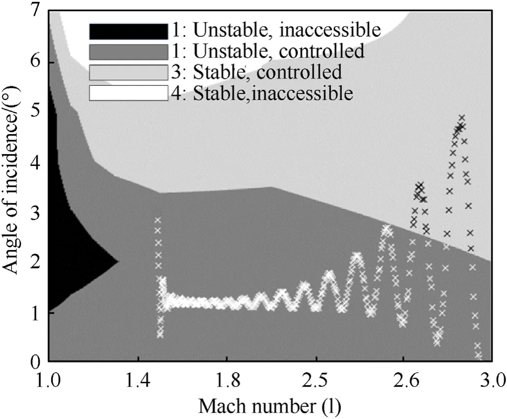
Fig. 20. Total angle of incidence vs. Mach number,1000 m/s muzzle velocity,1500 m range, 50 m/s target cross velocity.
Fig.20 Shows the trajectory in the Mach-alpha plane,where the projectile starts at 1000 m/s sea level conditions (M= 2.9) in the unstable,controlled region.The projectile remains in the unstable,controlled region for most of the flight. The angle of incidence in this figure is the combination of the yaw and pitch angles,shown in Fig. 21. Att= 0 s, the target at 1500 m range is at the 0 m cross distance mark and starts moving to the left in Fig.17 at 50 m/s when the projectile is fired.The projectile controller,acting upon the lineof-sight rate, commands an angle of incidence that will bring the projectile on an interception course, while increasing the angle of incidence to account for the gravitational pull. Together with the oscillation in pitching angle, Fig. 21 clearly shows this upward trend. The projectile furthermore shows a slowly damped oscillating yawing motion throughout flight, that is initiated when the projectile initiates the course-correction towards the predicted impact point.
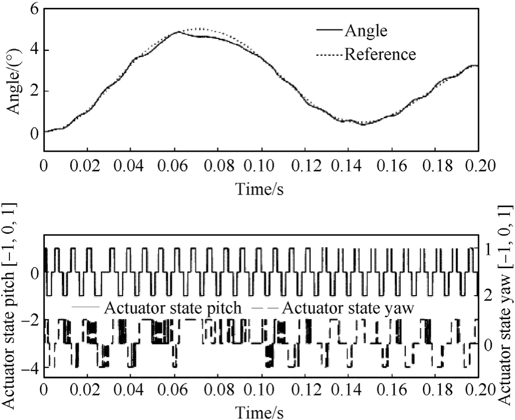
Fig. 22. Total and commanded (reference) angle of incidence (top) and actuator state plot (bottom),1500 m range, 50 m/s target cross velocity.
Fig.22 shows the total and commanded angle of incidence in the top figures and corresponding actuator states for pitching and yawing motion in the bottom plot.
For maximum effect on target, the impact velocity must be as high as possible.After 2.18 s the target at a 109 m cross distance is successfully hit with a final projectile velocity of 507 m/s,only 3 m/s,or 0.6%lower than the impact velocity in the previous,stationary target case. This means the act of steering the projectile using the Proportional Navigation scheme in this current case will lead to target hit and will have an end-effect on the target that is similar to the effect on a stationary target. The oscillation in yawing motion may be reduced by optimization of the controller. With only very limited effect on impact velocity, this optimization is beyond the scope of this initial feasibility study.
4.1.2. 1500 m range,fleeing, weaving target
The last case considered in this study is an initially stationary target at 1500 m range. The target moves away from the shooter with an acceleration of 5 m/s2in the axial direction. At the same time, it makes a weaving motion in the cross direction with an amplitude of 5 m at 0.5 Hz frequency. Fig. 23 shows a top view of the projectile trajectory.As the target weaves in the cross direction,the projectile follows the target, which is expressed by its crossdirectional offset of slightly more than 4 m to either side, before hitting the target. Viewing the trajectory from the side, Fig. 24 shows that the projectile has some initial oscillation in the vertical plane and a maximum downward deflection of 1.5 cm, due to gravitational pull.
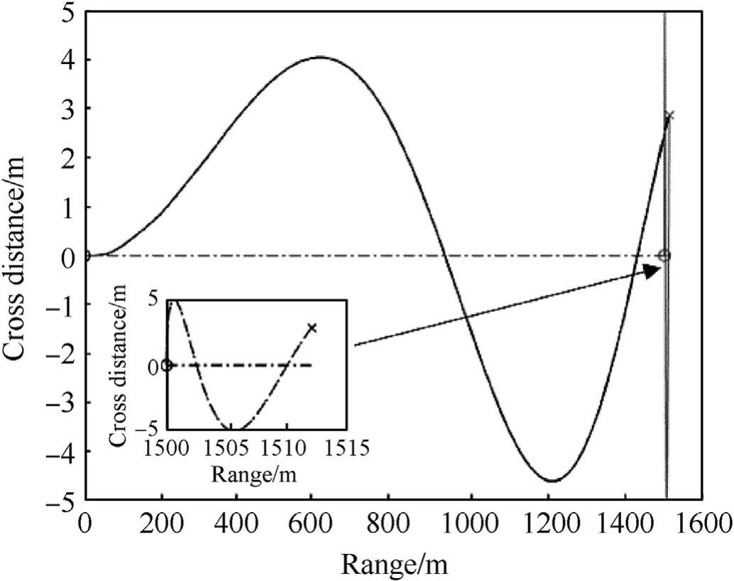
Fig. 23. Trajectory top view,1000 m/s muzzle velocity,1500 m range, weaving target.
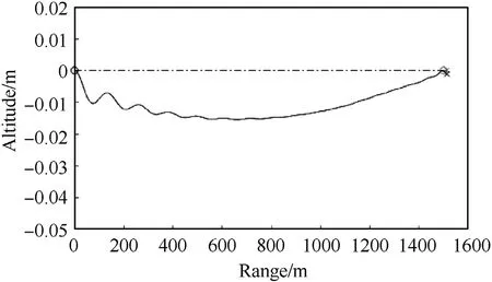
Fig.24. Trajectory side view,1000 m/s muzzle velocity,1500 m range,weaving target.
The previous figures show that the SPRC projectile is able to hit a weaving target with weaving parameters indicated above. After a flight time of 2.19 s, the projectile hits the target at a distance of 1512 m at a velocity of 506 m/s,only 4 m/s,or 0.8%slower than the hit velocity against the stationary target.Again,it can be concluded that in this case,the act of steering will only have a minor influence on the end-effect on the target.
To achieve this trajectory, the projectile needs pitch and yaw angles as indicated in Fig. 25. In the Mach-alpha plane, Fig. 26 shows the total angle of incidence, which is the combination of these angles.The figure shows that the total angle of incidence falls within the unstable, controllable area. This means that the projectile is aerodynamically unstable,but is controlled at the desired angle of incidence by the two orthogonal control systems.

Fig. 25. Projectile pitch and yaw angles, 1000 m/s muzzle velocity, 1500 m range,weaving target.
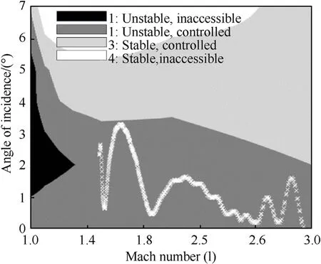
Fig. 26. Total angle of incidence in the Mach-alpha plane,1000 m/s muzzle velocity,1500 m range, weaving target.
4.2. Outlook
The current analyses have shown the capability of the hypothetical SPRC projectile to hit stationary, moving and weaving targets. In the current analysis, a target range of 1500 m was chosen,maintaining supersonic flight conditions for the SPRC projectile.In this regime, the guidance algorithm of Proportional Navigation,using the rate of the line of sight vector to determine the required projectile accelerations has been shown to lead to target hits in the scenarios simulated in this study. Follow-up activities will include the determination of a suitable guidance scheme for the transonic and subsonic regimes that make use of the small remaining control force in these situations. Such future efforts will illustrate the projectile behavior when engaging longer-range targets.
Currently the SPRC control is based on having a measurement of the angle of incidence. Additional effort will be required to determine practically achievable sensor measurements for the SPRC control to either determine this angle of incidence or to use other measurements,such as the combination of higher harmonics of the line-of-sightrate,inertialmeasurementsorpressure measurements.
5. Conclusions
This work has presented a feasibility study in the application of SPRC technology in a hypothetical SPRC Projectile. Modelled aerodynamic behavior of this projectile, experiment-based control latency and -forces, a bang-bang control algorithm with tunable decision planes and a Proportional Navigation scheme were combined in a detailed Matlab/Simulink®model.SPRC is characterized by reduction of control force with reducing Mach number.Furthermore, aerodynamic stability of the projectile decreases during flight. Aerodynamic analysis of the projectile shape designed in this work showed that the stable angles of incidence were increased from 1.5◦to at least 6◦at the intermediate Mach numbers and higher for Mach>2.5 and < 0.8. Assuming the projectile can detect the location of the target and the projectile can measure its angle of incidence, detailed trajectory simulation indicates that SPRC is able to keep the projectile stable and under required angles of incidence imposed by the guidance scheme despite the instability of the projectile and the declining control force. In three scenarios, i.e. a stationary target, a target moving sideways with 50 m/s and a weaving target at 1500 m, theoretical proof-of-concept was provided for the assumed 30 mm caliber SPRC projectile under supersonic flight conditions.The simulations showed that target cross-velocity and weaving only led to impact velocity reduction of up to 0.8%, signifying only a very small difference in target end-effect.
Currently only the supersonic flight regime has been analyzed,for which Proportional Navigation has been shown to be a suitable guidance scheme, although a beam-rider concept can be envisioned as a low-cost alternative.The current feasibility study shows that for supersonic flight conditions,SPRC can be a suitable fin-less control technology for gun-launched mid-caliber projectiles,under the assumption that a reliable measurement of the Line-Of-Sight to the target and a measurement of the angle of incidence and roll angles are available. Further work will focus on transonic and subsonic controllability and practical measurements on which to base the SPRC control technology.
Declaration of competing interest
The authors declare that they have no known competing financial interests or personal relationships that could have appeared to influence the work reported in this paper.
Acknowledgements
This research did not receive any specific grant from funding agencies in the public, commercial, or not-for-profit sectors.
杂志排行
Defence Technology的其它文章
- A review on lightweight materials for defence applications: Present and future developments
- Study on the prediction and inverse prediction of detonation properties based on deep learning
- Research of detonation products of RDX/Al from the perspective of composition
- Anti-sintering behavior and combustion process of aluminum nano particles coated with PTFE: A molecular dynamics study
- Microstructural image based convolutional neural networks for efficient prediction of full-field stress maps in short fiber polymer composites
- Modeling the blast load induced by a close-in explosion considering cylindrical charge parameters
