Hardware-in-loop adaptive neural control for a tiltable V-tail morphing aircraft
2023-05-06FuxingQioJingpingShiXioboQuYongxiLyu
Fu-xing Qio ,Jing-ping Shi ,b,* ,Xio-bo Qu ,b ,Yong-xi Lyu ,b
a School of Automation,Northwestern Polytechnical University,Xi'an,710129,China
b Shaanxi Province Key Laboratory of Flight Control and Simulation Technology,Xi'an,710129,China
Keywords:Morphing aircraft Back-stepping control Adaptive control Neural networks Radial basis function
ABSTRACT This paper proposes an adaptive neural control(ANC)method for the coupled nonlinear model of a novel type of embedded surface morphing aircraft which has a tiltable V-tail.A nonlinear model with sixdegrees-of-freedom is established.The first-order sliding mode differentiator (FSMD) is applied to the control scheme to avoid the problem of “differential explosion”.Radial basis function neural networks are introduced to estimate the uncertainty and external disturbance of the model,and an ANC controller is proposed based on this design idea.The stability of the proposed ANC controller is proved using Lyapunov theory,and the tracking error of the closed-loop system is semi-globally uniformly bounded.The effectiveness and robustness of the proposed method are verified by numerical simulations and hardware-in-the-loop (HIL) simulations.
1.Introduction
For the past two decades,morphing aircraft has become an interesting topic due to its superior flight performance.Compared to the traditional fixed-wing aircraft,this aircraft has multi-mission adaptability by altering the aerodynamic structure of the aircraft[1—3].With the development of several research fields such as actuators,materials,structure,and control theory,morphing aircraft can easily and effectively implement multiple missions in different flight environments [4—8].As a complicated system,the control of morphing aircraft is faced with the huge variations of aerodynamic parameters,the existence of external disturbances,and internal uncertainties,which is one of the major hot spots of research on morphing aircraft [9].
In previous research,most of the extant control schemes mainly focus on the decoupled longitudinal model,and most of the control objects in this literature are the sweep-back wings aircraft which is similar to the F-14 Tomcat.The aircraft with morphing wing technology mentioned in many studies are the Firebee [10]and the MFX-2 [11].Based on the unmanned aerial vehicle (UAV) Firebee,Yan et al.[12]designed a morphing aircraft that has a pair of variable-sweep wings.And designed a controller by proportionalintegral-derivative (PID) with different gains for the longitudinal model of this aircraft.Then,an adaptive super-twisting algorithm sliding mode control method was presented based on their existing research work [13].According to the longitudinal dynamics of the MFX-2,Wu et al.[14]proposed an adaptive approach based on neural network and high-order integral chained differentiator.Then they proposed a control scheme by composite switching neural prescribed-performance [15].And for the longitudinal dynamics with input-output constraints and unknown parameters,a modified control method by adaptive neural dynamic surface has been developed based on their previous work [16].Based on the same longitudinal model as Wu et al.,Wang et al.[17]modeled the longitudinal altitude motion as a switched nonlinear system in the form of a lower triangle.And the control scheme was proposed for it based on adaptive dynamic programming and switched nonlinear systems.
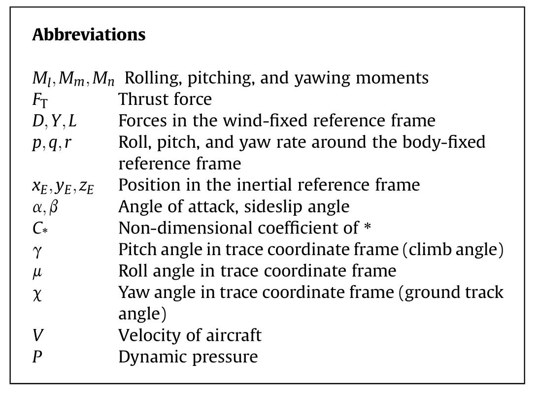
In addition to the morphing aircraft with swept-back wings,some scholars have designed different types of morphing aircraft and proposed corresponding control methods.Inspired by a seagull's wing structure,Grant et al.[18]designed a multiple-joint morphing-sweep aircraft,which is independent on the wings along with on the inner and outer segments.And they analyzed the flight dynamics under the different swept-back wing configurations in symmetric and asymmetric cases.In Ref.[19],they advanced their work by studying the longitudinal dynamics of this aircraft and presented a time-varying characteristic equation for the influence of various morphing schemes.Based on X—24B,Jiao et al.[20]researched a hypersonic morphing vehicle with retracted winglets.According to the longitudinal model of this aircraft,they proposed a new learning approach for the control law of mode switching based on a type-2 Takagi-Sugeno-Kang fuzzy neural network.Yue et al.[21]investigated a folding-wing morphing aircraft and used the linear parameter varying (LPV) approach to build a longitudinal model of the aircraft and simulated the longitudinal dynamic response during wing folding.Based on the LPV model,they designed a pair of linear controllers by the selfscheduled gain H∞robust control approach to ensure the control effect of aircraft altitude and speed during the process of wing folding [22].
Despite the designs and control schemes of morphing aircraft have made significant progress in recent years,some phenomena and issues need to be considered:
(1) Many researchers have focused on the sweep-back-wing morphing aircraft as the control object,and the transformation process of this type of morphing aircraft only has notable changes in the longitudinal dynamics.
(2) And most of the control schemes and performance analyses are based on the decoupled longitudinal model,however,there is not much analysis and research on the lateral dynamics of the morphing aircraft.Essentially,the controlled object is a single input single output model,it is difficult to reflect the complexity of morphing aircraft and the actual performance of the controller.And most previous researches have only considered the control of the longitudinal system,rather than considering longitudinal and lateral dynamics as a whole system.
(3) In the field of morphing aircraft control,few scholars carry out HIL simulations after numerical simulations,they did not verify the control method by HIL simulation in a complex environment.However,it is very common to use HIL simulation to verify the feasibility and reliability of the algorithm in some fields such as navigation and vehicle control[23—25].
Inspired by the mentioned discussion,this paper presents a new type of embedded surface morphing aircraft with an adjustable Vtail and proposes an ANC method for the coupled nonlinear model of this novel morphing aircraft.The main contributions of this work are listed as follows:
(1) A novel morphing aircraft which is a tailless blended wing/body aircraft with an adjustable V-tail is designed to satisfy the requirements of different flight environments and missions.Based on a large number of aerodynamic data from different V-tail configurations,a nonlinear model with six degrees of freedom is established.
(2) The FSMD is introduced into the traditional back-stepping control (TBC) scheme to avoid the “differential explosion”.To solve the problem of the external disturbance and uncertainty of the model,radial basis function (RBF) neural networks (NNs) are introduced,and an ANC controller is proposed based on this design idea.
(3) By contrast to studies that focus only on a linearized model with decoupled longitudinal dynamics,the controller presented in this paper is designed for the longitudinal and lateral dynamics of the whole system.And the stability of the closed-loop system is proved by using Lyapunov synthesis based on stability analysis.
(4) After numerical simulations,the robustness and effectiveness of the proposed method are verified by HIL simulations.
The layout of this paper is organized as follows.Section 2 introduces the preliminaries and problem formulation.And section 3 presents an adaptive neural controller and the corresponding stability analysis.The numerical simulations and HIL simulations are given in section 4.Finally,section 5 concludes the work of this study.
2.Preliminaries and problem formulation
2.1.Morphing aircraft specification
A novel type of embedded surface morphing aircraft,named XQ-8A which is shown in Fig.1(a),has been devised by a research group at the Northwestern Polytechnical University,Xi'an.The takeoff weight of the XQ-8A is 28 kg and the cruise speed is designed to be 150 km/s at an altitude of 1000 m.The key parameters of this aircraft are given in Table 1.And the aerodynamic data of the aircraft are shown in Fig.2.
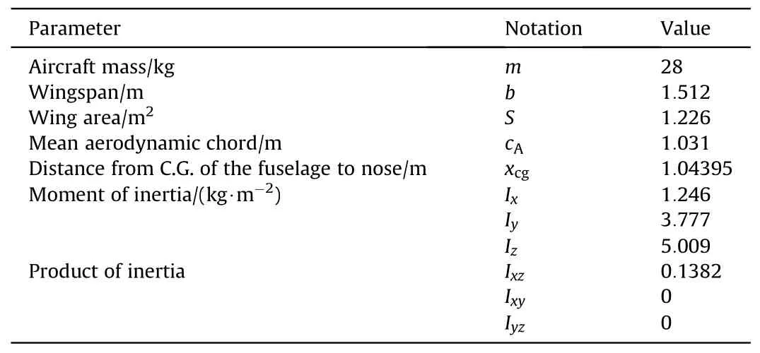
Table 1 Main parameters of XQ-8A.

Table 2 Parameters of the ADRC.
All control surfaces on the XQ-8A are shown in Fig.1(b).It has four empennage surfaces and a pair of variable flight control surfaces (VFCSs),which can form a V-tail or be embedded in the fuselage.And there are twin all-moving fins on the VFCSs.
The control surfaces are embedded in the fuselage and the aircraft has a flying-wing configuration when the angle of the V-tail is zero (Λ=0°).Because of the mechanical dead zone,the allmoving fins cannot deflect when the angle of the V-tail is less than 15°(Λ<15°).Thus,only when the angle of the V-tail is greater than or equal to 15°(Λ ≥15°) do the all-moving fins work,operating as a rudder.The other two pairs of empennage surfaces can be divided into an inner control surface (CS1) and an outer control surface (CS2) according to their positions.The range of the V-tail angle (Λ) is 0°-90°.And the range of flight control surfaces CS1(δcs1R,δcs1L),and CS2 (δcs2R,δcs2L) is limited to -20°-20°.The position limit of the all-moving fins (δvcsR,δvcsL) is -15°~15°when the angle of the V-tail exceeds 15°(Λ ≥15°).
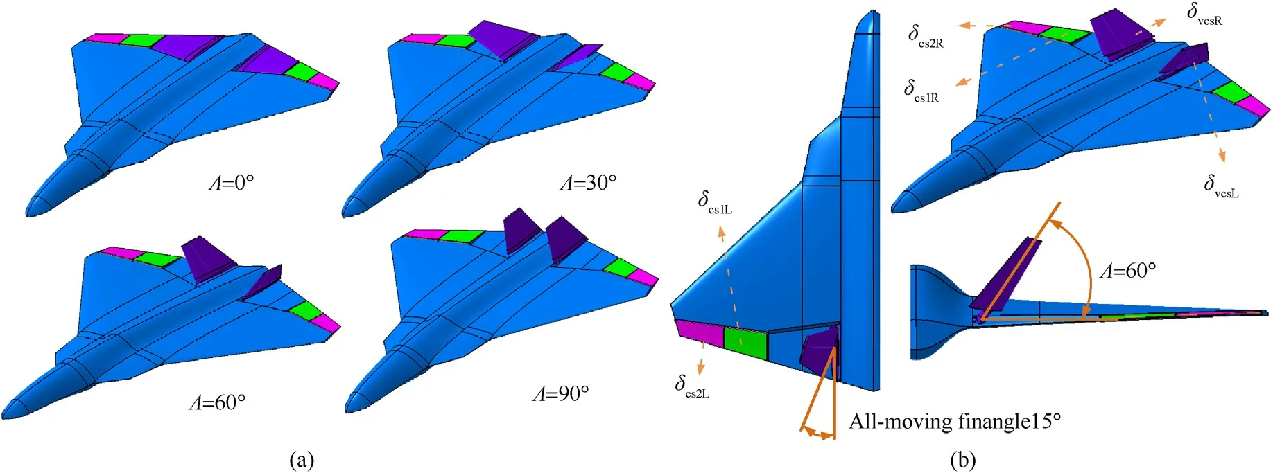
Fig.1.Morphing aircraft XQ-8A: (a) Different morphing configurations;(b) Definition of control surface.
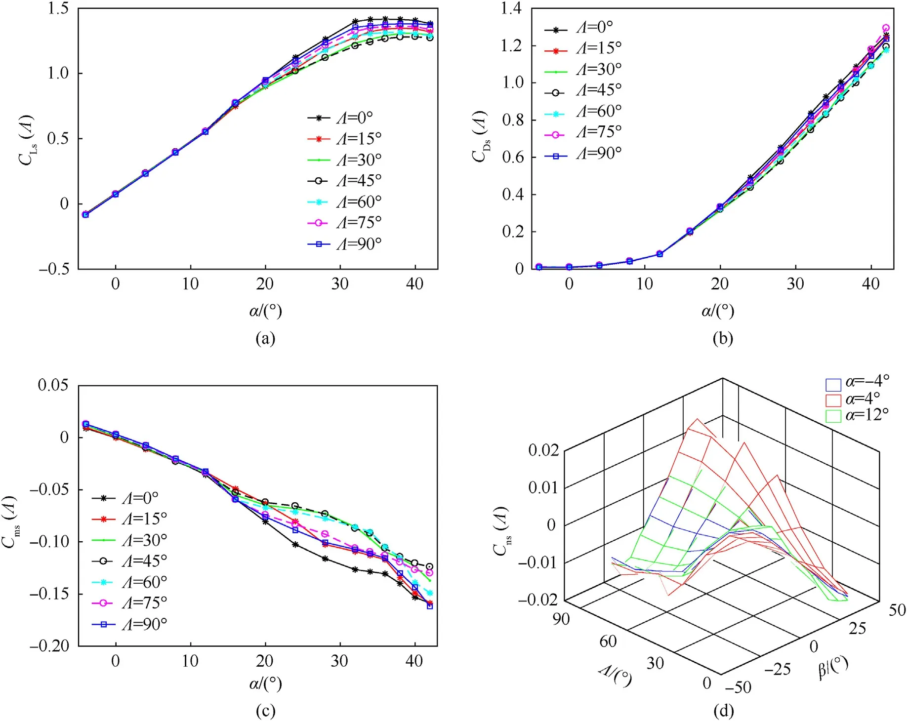
Fig.2.Some aerodynamic data of XQ-8A: (a) Lift coefficient;(b) Drag coefficient;(c) Pitching moment coefficient;(d) Yawing moment coefficient.
2.2.Dynamic model
The control-oriented model of the dynamics of this aircraft are as follows:
For simplicity,the dynamic model in Eq.(2) and Eq.(3) can be converted as
Assumption 1.The deflection of the control surface has negligible effects on the aerodynamic force component [26,27],i.e.,g1u(xm)u≈0.
Considering Assumption 1,the modeling uncertainty and external interference,the dynamic model can be written as
where parts(a)and(b)in Eq.(8)denote two separate subsystems.The functions fi(•)and gi(•)are given in Appendix A.Δ1∊R3and Δ2∊R3denote the approximation errors in each subsystem,respectively.To deal with the system uncertainty in each subsystem effectively,RBFNNs are adopted.
Assumption 2.The command signal y1d=x1d=[αdβdμd]Tis bounded and continuously differentiable,and its first derivative(1d) is also bounded.
Assumption 3.The matrixes g1(xm)∊R3×3and g2(xn)∊R3×6are invertible.
Remark 1.Note that g1u(xm)denotes the aerodynamic force component caused by the control surface deflection and numerical analysis finds that the control surfaces have a negligible influence on the aerodynamic force,so the size of g1u(xm)is negligible.Assumption 2 ensures that the command signal for aircraft control satisfies the conditions of continuous differentiability and a bounded first derivative.Because the control surfaces of the aircraft are designed to control each axis angular rate of aircraft independently,g2(xn)is invertible for all cases.The morphing aircraft in this paper has six control surfaces,so g2(xn)∊R3×6is a matrix of three rows and six columns,and g2(xn)-1∊R6×3is a pseudo-inverse matrix.
2.3.Neural networks
RBFNNs are used to approximate the continuous function [28].An arbitrary continuous function ⊿∊R can be denoted as follows:
where ω∊RNis the weight matrix of the NN (N>1 denotes the number of neural network nodes,andN=50 in this paper),ρ∊RNis the RBF matrix,and ε∊Rexpresses the approximation error of the NN.
Definition 1.The function trv(A)is defined to obtain the vectors of diagonal elements of the matrix A∊RM×M.trv(A)and A are defined as follows:
In Eq.(8),Δ1and Δ2denote the approximation errors of the two subsystems,and are defined as follows:
The RBF ρi,j(xini)usually takes the form of a Gaussian function
where ζiniis the center vector of the RBF and σi,jis thejth RBF bandwidth.The specific definitions of xiniand ζiniare as follows:
Taking (ω1)Tρ1(xin1)as an example,the structure of the NN is shown in Fig.3.
2.4.Active disturbance rejection control
Active disturbance rejection control (ADRC) has achieved satisfactory performance for the uncertain nonlinear system [29,30].The ADRC approach is applied to design the velocity controller in this paper.ADRC comprises 3 parts: the extended state observer(ESO),the tracking differentiator(TD),and the nonlinear state error feedback(NLSEF).ADRC approach is applied to design the velocity controller,the structural diagram of velocity control is shown in Fig.4.
The algorithm of TD is expressed as follow:
ESO is used to observe the internal state and estimate the unpredictable state of the system.It is the core of ADRC.Form as follows:
3.Controller design and stability analysis
3.1.Controller design
The proposed controller is designed for the attitude subsystem,which contains a two-step recursive design procedure.The FSMD is introduced into the TBC scheme to avoid the problem of “differential explosion”and RBFNNs are used to solve the problem of the external disturbance and uncertainty of the model.The diagram of the control scheme is shown in Fig.5.
Step 1:Define e1=[e1,e2,e3]T∊R3as the tracking error and y1dis the reference signal.The derivative of e1can be formulated as
Define x2das the desired signal of the inner subsystem.The virtual control law of the outer system can then be designed as
where K1∊R3×3is a diagonal positive-definite matrix anddenote the estimations of W1.
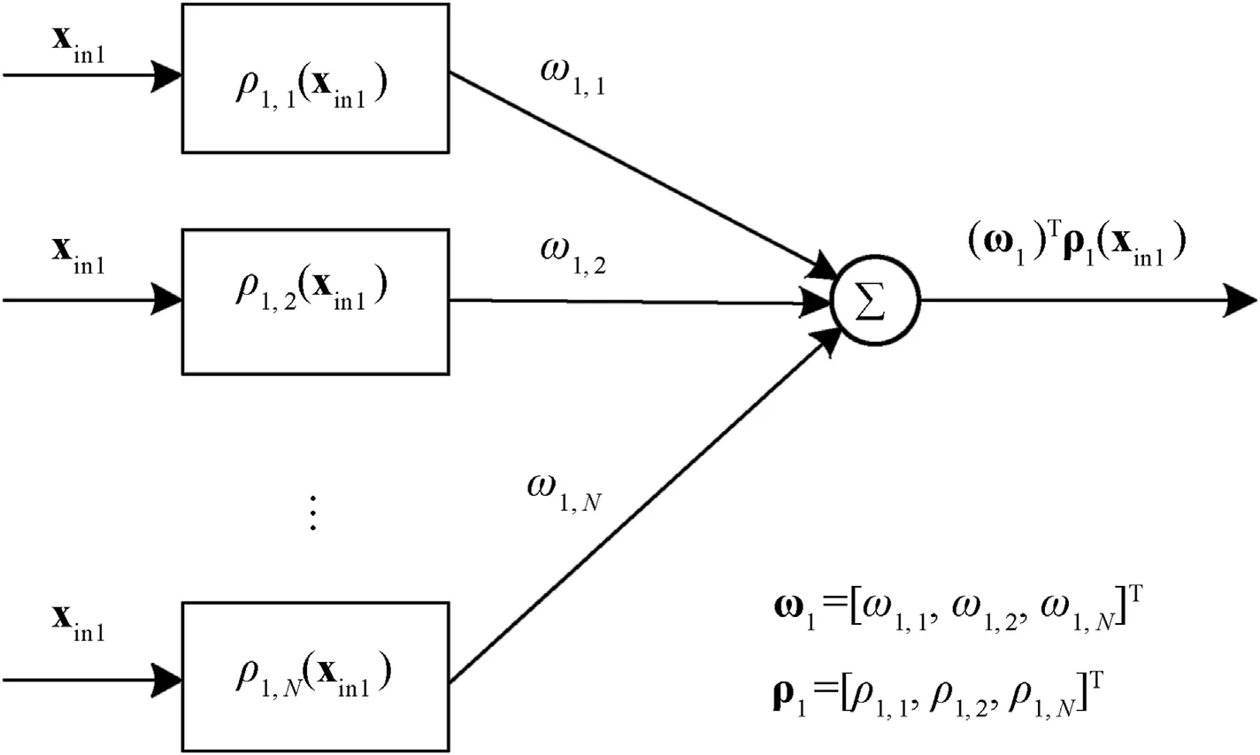
Fig.3.The structural diagram of NN.
Lemma 1.The first-order sliding mode differentiator (FSMD) is designed as
Step 2:To prevent the problem of the differential explosion,according to Lemma 1,we have
Define e2=[e4,e5,e6]T∊R3as the tracking error of the inner subsystem.So2can be expressed as
where ηiis a positive design constant and Γi∊RN×Nis a diagonal positive-definite matrix.
3.2.Stability analysis
Define the errors
Then,note that the following inequalities hold
Lemma 2.For any vectoraandb,the following inequality holds:
Lemma 3.(Young’s inequality[32,33])The following inequality holds for any matrixAwhich‖A‖≤amax,amax>0.
For convenience,in the following,abbreviations such as f1are used for f1(xm).According to the above equations,the time derivative of e1and e2are given by
According to the matrix operation principle,the following expressions can be obtained
Thus,Eq.(32) and Eq.(33) can be rewritten as
Note thatg1min≤‖g1‖,ηi≤ηmaxand λmin(K1),λmin(K2),and λmin(Γi)denote the minimum eigenvalues of the corresponding matrices.Additionally,λmin(Γi)≥λminΓ(i=1,…,6).
Therefore,the derivative ofLwis obtained as
To ensure closed-loop stability,the design parametersC1should be selected such thatC1>0.According to Eq.(36),it can be shown that the tracking error of the closed-loop system is semi-globally uniformly bounded.
4.Simulations and results
4.1.Numerical simulations
To illustrate the performance of the proposed method,two setsof numerical simulations are devised,and corresponding comparison and analysis are performed.
The control parameters of the controllers are shown in Tables 2 and 3.For the RBFNNs component of the proposed controller,each control channel includes 50 NN nodes (N=50).The RBF bandwidths σi,j(i=1,2,3,j=1,…,50)in the first subsystem are evenly spaced in the scope [3,4].And the corresponding NN weight elements ωi,j(i=1,2,3,j=1,…,50)are initially set to random values in the scope[0,1].In the second subsystem,the initial values of the NN weight elements ωi,j(i=4,5,6,j=1,…,50)are also random in the range of[0,1].And the corresponding RBF bandwidths σi,j(i=4,5,6,j=1,…,50) are evenly spaced in the scope [20,21].

Table 3 Parameters of the ANC.
4.1.1.Verification under the static V-tail
In this scenario,the angle of the V-tail is fixed at 45°,and the initial trim conditions are set as [V0,h0,α0,β0,μ0]=[41.67 m/s,1000 m,4.849°,0°,0°].The change of the reference signal is as follows:
The tracking performance in this simulation is revealed in Fig.6(a).Fig.6(b)shows the root mean square errors (RMSEs)and the settling time.The results suggest that the proposed method decreases the RMSE and reduces the settling time under the condition of the static V-tail.
4.1.2.Verification under the dynamic V-tail with wind and aerodynamics uncertainties
In this scenario,a new numerical simulation is carried out to verify the efficiency and robustness of the proposed method.The Vtail angle is variable and the wind disturbance and aerodynamic coefficient variation are taken into consideration.The wind model is the Dryden Wind Turbulence Model in Simulink,and the wind velocities denoted in the three-body axes areuw,vw,andww,as revealed in Fig.7(b).The aerodynamic coefficient variation is expressed as:
The V-tail command signal is shown in Fig.7(a) and the initial trim conditions are set as [V0,h0,α0,β0,μ0]=[41.67 m/s,1000 m,4.774°,0°,0°].As can be seen from Fig.8(a),the proposed controller has better robustness and performance and the RMSAEs revealed in Fig.8(b) support this conclusion.
4.2.HIL simulations
4.2.1.HIL simulation setup
To further validate the performance and robustness of the proposed method,the corresponding methods are transferred to the HIL simulation.And three sets of HIL simulation scenarios are devised.
The HIL simulation system contains the following components:(1) an autopilot with sensors for controller implementation and measuring angular velocity,(2)a real-time simulation computer for implement the morphing aircraft model,(3) a 3-axis turntable for driving the attitude motion of the autopilot,(4) a visual display software for displaying real-time flight data of morphing aircraft.Fig.9 Shows the structural diagram of the HIL simulation platform.
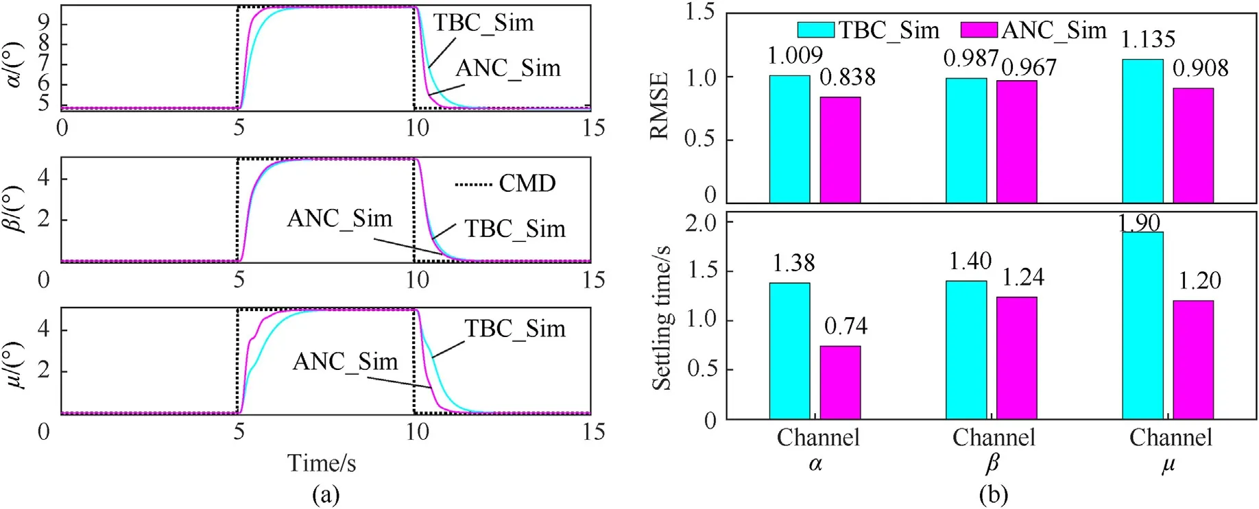
Fig.6.Simulation results comparison in scenario 1: (a) Tracking performance;(b) RMSEs and settling time.
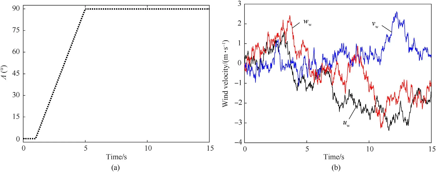
Fig.7.V-tail command signal and wind velocity: (a) V-tail command signal;(b) Wind velocity.
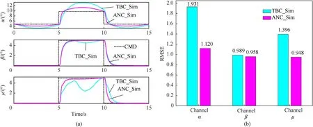
Fig.8.Simulation results comparison in scenario 2: (a) Tracking performance;(b) RMSEs.
The autopilot was developed by our laboratory,which integrated a high-precision IMU integrated module for measuring the angular velocities of morphing aircraft.The real-time simulation computer runs the morphing aircraft model by MATLAB/xPC Target,a PC-based real-time control system from MathWorks [34,35].It receives the control signals from the autopilot and sends the states of morphing aircraft to autopilot.And it also sends the states to the visual display software via the UDP for observing the kinematic characteristics of the aircraft intuitively.The autopilot is fixed on a 3-axis turntable which was driving by the signals which are the angular velocities of morphing aircraft from the real-time simulation computer.Considering the real physical data source,the angular velocities used by autopilot comes from the data measured by IMU (sensor data,p,q,r) instead of the data calculated by the real-time computer (xPC data,p,q,r),and the comparison of the two data is shown in Fig.10.And Fig.11 shows the snapshot of the HIL simulation platform.
4.2.2.Verification under the static V-tail
In this scenario,the angle of the V-tail is fixed at 45°,and the initial conditions are set as[V0,h0,α0,β0,μ0]=[41.67 m/s,1000 m,4.849°,0°,0°].The reference signals are the same as scenario 1.The tracking performance is revealed in Fig.12(a).And the RMSEs are revealed in Fig.12(b).
Compared with the previous numerical simulation results,the effect of HIL experiment becomes worse under the same control command.The main reason is the change of aircraft angular velocity data source of the controller.As shown in Fig.9,the angular velocities (xPC data,p,q,r) calculated by the real-time simulation computer drives the turntable to move,and the IMU of the autopilot is measuring the angular velocities (sensor data,p,q,r).Fig.10(a)shows the angular velocities under different information sources.It can be seen that there are errors and delays in the angular velocities used by the controller.Under such harsh signal interference,the two controllers can also track the reference signal well,which shows that the robustness of the controllers is good.As expected,the proposed method has a better tracking effect,especially on the α and μ channels.The comparison of RMSEs in Fig.12(b) and Table 4 supports this conclusion.
4.2.3.Verification under the dynamic V-tail
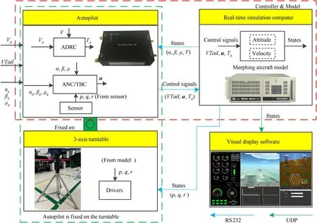
Fig.9.The architecture of the HIL simulation.
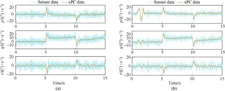
Fig.10.Angular velocities under different information sources: (a) Data in scenario 3;(b) Data in scenario 4.
In scenario 4,the V-tail command signal is the same as in scenario 2,and the initial trim conditions are set as [V0,h0,α0,β0,μ0]=[41.67 m/s,1000 m,4.774°,0°,0°].The angular velocities under different information sources are shown in Fig.10(b).The tracking performance and the RMSEs are shown in Fig.13.Table 4 shows the detailed comparison of RMSEs in this scenario.Scenario 4 adds the V-tail control command,which increases the interference to the system,so the control effect becomes worse compared with scenario 3.However,the results still support the previous conclusions,and it can be concluded from the detailed data in Table 4 that the greater the interference to the system,the better the effect of ANC controller compared to the TBS controller.

Table 4 Comparison of the RMSEs of different HIL simulations.
Although the obtained outcomes still support the previous conclusions,it can be observed through Fig.13(a)that around 1.7 s,the effects of both controllers become very poor.By comparing the V-tail control command in Fig.7(a),it can be found that the V-tail angle is less than 15°at 1.7 s before.Through analysis,it is found that this phenomenon is also following the objective laws of physics.Due to the mechanical dead zone,the all-moving fins cannot work when the V-tail is less than 15°.In this situation,the lateral stability and controllability of the aircraft become worse.And from the simulation in the 5 s of Fig.13(a),it can be noticed that the performance of the proposed controller is preferred over the TBS controller when Λ<15°.
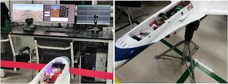
Fig.11.The snapshots of the HIL simulation platform.
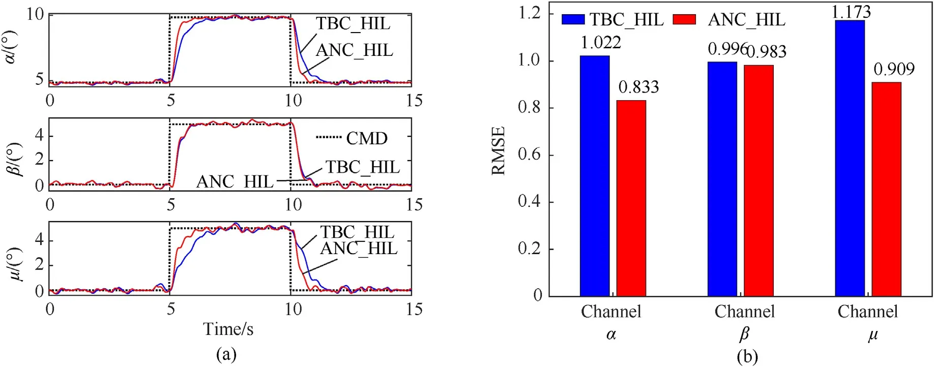
Fig.12.Simulation results comparison in scenario 3: (a) Tracking performance;(b) RMSEs.
Leaving aside the effect of V-tail on the aircraft,a new experiment (scenario 5) is designed.In this scenario,the simulation conditions are the same as scenario 4 except for the V-tail command signal as shown in Fig.14(a).The angular velocities under different information sources are shown in Fig.14(b).The tracking performance and the RMSEs which are shown in Fig.15 and Table 4 also support the conclusion that the proposed method is superior.The next step to improve the simulation effect of the HIL experiment should start with the data source of the sensor and filter the state required by the controller.This will increase the effectiveness of the controller,which is also a way of our research in the future.
5.Conclusions
This paper presented a novel morphing aircraft that has an adjustable V-tail.An adaptive neural control method using RBFNNs was proposed and the longitudinal and lateral channel flight controller was designed by the proposed method.Using Lyapunov theory,the parameter ranges of the proposed method were derived and the Lyapunov stability for the proposed methods was proved.To verified the performance of the method in terms of rapidity,accuracy,and robustness,numerical and HIL simulations across five scenarios were designed.The results show that the proposed method works well with good robustness and tracking performance.
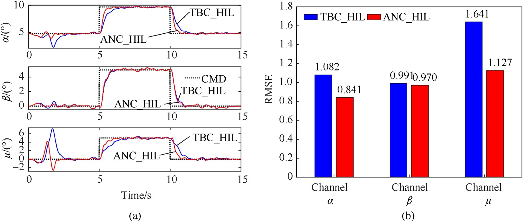
Fig.13.Simulation results comparison in scenario 4: (a) Tracking performance;(b) RMSEs.
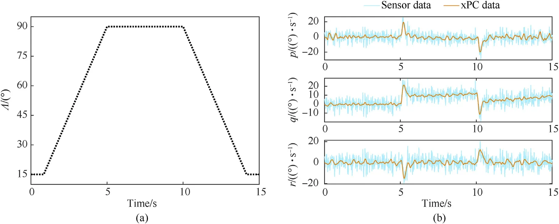
Fig.14.New V-tail command signal and angular velocities: (a) New V-tail command signal;(b) Angular velocity.
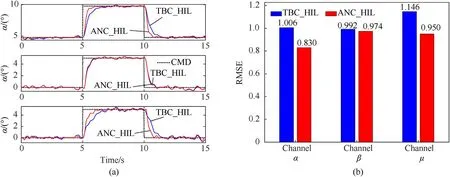
Fig.15.Simulation results comparison in scenario 5: (a)Tracking performance;(b)RMSEs.
Declaration of competing interest
The authors declare that they have no known competing financial interests or personal relationships that could have appeared to influence the work reported in this paper.
Acknowledgments
This work was funded by the National Natural Science Foundation of China (No.61573286),the Natural Science Foundation of Shaanxi Province (2019JM-163,2020JQ-218),the Fundamental Research Funds for the Central Universities (3102019ZDHKY07),and supported by Shaanxi Province Key Laboratory of Flight Control and Simulation Technology.
Appendix A
where
Note that abbreviations are used for aerodynamic coefficients,such asClsforCls(Λ).
杂志排行
Defence Technology的其它文章
- Resilient tightly coupled INS/UWB integration method for indoor UAV navigation under challenging scenarios
- Microfluidic assisted 90%loading CL-20 spherical particles:Enhancing self-sustaining combustion performance
- Dual Attribute Adversarial Camouflage toward camouflaged object detection
- GO/HTPB composite liner for anti-migration of small molecules
- Benchmark calculations and error cancelations for bond dissociation enthalpies of X—NO2
- One-step green method to prepare progressive burning gun propellant through gradient denitration strategy
