Quasi-in vivo corrosion behavior of AZ31B Mg alloy with hybrid MWCNTs-PEO/PCL based coatings
2022-12-30MortezDvriMsoudAtpourMrtMohednoHugoMornhezJunRodrguezHernndezEndzheMtykinRulArrlAoozrTherizdeh
Mortez Dvri,Msoud Atpour,Mrt Mohedno,Hugo Mor Sánhez,Jun Rodríguez-Hernández,Endzhe Mtykin,Rul Arrl,Aoozr Therizdeh
a Department of Materials Engineering,Isfahan University of Technology,84156-83111 Isfahan,Iran
b Departamento de Ingeniería Química y de Materiales,Facultad de Ciencias Químicas,Universidad Complutense,28040 Madrid,Spain
c Institute of Polymer Science and Technology (CSIC),Polymer Functionalization Group,Madrid 28006,Spain
Abstract This study investigated the effects of multi-walled carbon nanotubes(MWCNTs)and polycaprolactone(PCL)on the quasi-in vivo corrosion behavior of AZ31B Mg alloy treated by plasma electrolytic oxidation (PEO).Thin (∼2 μm,PCTPCL4) and thick (∼60 μm,PCTPCL6) PCL layers were applied only onto the MWCNTs-PEO coating (PCT) as it showed better corrosion performance.Findings reveal that incorporation of MWCNTs induced several structural and functional modification in the PEO coating,such as increased roughness,a thicker inner barrier layer,and reduced hydrophilicity.
Keywords: AZ31B Mg alloy;Plasma electrolyte oxidation (PEO);Multi-walled carbon nanotubes (MWCNTs);Quasi-in vivo condition;Polycaprolactone(PCL).
1.Introduction
Every year,millions of people experience bone fractures due to sports injuries,car accidents,falls,or osteoporosis [1].Nowadays,metallic biomaterials such as titanium,stainless steels,and cobalt-chromium alloys are commonly employed to repair or replace injured bone tissues [2].However,these alloys present three main disadvantages: (i) release of harmful ions that affect cell adhesion and proliferation [3];(ii)stress-shielding effect due to a higher elastic modulus compared to that of the bone [4];and (iii) the necessity of a secondary removal surgery that inconveniences the patients and imposes additional costs to healthcare systems [5].Magnesium and its alloys are the promising new generation of materials for the fabrication of bone implants that overcome the abovementioned disadvantages.Specificall ,Mg participates in human body metabolism [6],is biodegradable [7],and has mechanical properties similar to those of cortical bone [8].
Local alkalization and excessive hydrogen evolution are the main risks associated with the accelerated degradation of magnesium implants [9].Plasma electrolytic oxidation (PEO)is an electrochemical surface treatment that can efficientl control the degradation rate of Mg alloys and simultaneously ensure an enhanced implant bioactivity through a tailored surface [10–12].However,long-term protection of Mg by PEO coatings is often compromised by their localized failures associated with the presence of micro-defects and the pseudopassivity of the ceramic-like fil [13,14].
In many works,modificatio of the morphology and composition of the PEO coatings have been studied to optimize their performance [15–22].In situincorporation of particles from suspension electrolytes and sealing of the coating pores are examples of recent efforts.In situincorporation of carbonbased micro/nano-particles,including graphene,graphene oxide,graphite and multi-walled carbon nanotubes (MWCNTs),have attracted a great deal of attention [23–27].MWCNTs in particular possess unique characteristics such as excellent tensile strength and a high aspect ratio that inhibits crack propagation via a bridging mechanism [28–30].The possibility of utilizing the MWCNTs for bone tissue engineering has been investigated in several studies.Those have shown that MWCNTs can be used in the structure of bone scaffolds due to their excellent mechanical properties and acceptable biocompatibility [31–34].A brief survey of previous works reveals the lack of sufficien study on the incorporation of MWCNTs into the PEO coating formed on Mg alloys.To the best of our knowledge,only two studies have been carried out in this area,namely,by Hwang et al.[23] and Daavari et al.[35].The former is focused on enhancing heat dissipation,whereas the second is concerned with the effect of MWCNTs on biotribology and biocorrosion.
Regarding the application of top-layers or sealing,there are many methods such as cold spray,sol-gel,electrophoresis,dip-coating,etc.[25,26,36–38].Among them,polymeric top-layers are an attractive approach for providing effective corrosion protection underin vivoconditions due to their easy application and low cost.Polylactic-co-glycolic acid (PLGA),poly l-lactic acid (PLLA),polylactic acid (PLA),and polycaprolactone (PCL) are common polymeric materials that have been investigated for load-bearing bone implants during recent years [39–42].PCL,a semi-crystalline polymer,has attracteda great attention due to its low cost,good biocompatibility,and sustainable biodegradability [43].However,stand-alone PCL lacks a suitable adhesion strength to the Mg alloy surface [44].The main advantage of PCL in comparison to other biodegradable polymers such as PLGA,PLA,and PLLA is its slower degradation rate.Its degradation takes 2–3 years;hence,a PCL layer is expected to provide more suitable protection for Mg substrate [45].Accordingly,several PCL-based studies have been carried out during recent years[46–50].
Predicting thein vivodegradation of temporary implants poses a challenge of paramount importance.Accordingly,in vitroexperiments should simulatein vivoconditions as realistically as possible.Choosing a proper buffering system is a critical factor that can help to obtain quasi-real results.In the body,pH blood regulation is managed by three main components with 2 of them based on Eq.(1): the brain acts as a pH sensor,lungs adjust the CO2concentration in the blood plasma,and finall ,kidneys are responsible for regulating HCO3−concentration [51–53].

Phosphate-buffered saline (PBS),Tris (hydroxymethyl)-aminomethane (Tris),and 2-[4-(2-hydroxyethyl)piperazin-1-yl]ethane sulfonic acid(HEPES)are the most common buffering agents that are usedin vitro.Several studies have reported that HEPES and Tris accelerate the corrosion rate of pure magnesium by 60 and 10 times,respectively [54,55].PBS has also been shown to alter the degradation rate of magnesium compared toin vivoconditions [56,57].Accordingly,HEPES,Tris,and PBS cannot provide an ideal simulated environment.Therefore,a CO2/HCO3−buffering system seems better suited forin vitroexperiments since it is quite similar to thein vivopH regulation system.
Providing hydrodynamic conditions during testing should also be considered.Indeed,electrolyte fl w facilitates masstransfer processes at the surface via diffusion and convection,thus influencin the degradation behavior of the tested material [58].
In the present study,a step-by-step surface modificatio strategy is applied to improve the biodegradation behavior of AZ31B Mg alloy used as a model alloy with a middleroadin vitroandin vivodegradation rates [59].The firs step is the fabrication of a PEO coating on the base metal.The second step is concerned with the structural modificatio of the PEO coating by incorporation of MWCNTs.In the third step,a thin PCL layer is applied to seal the pores using a dilute polymeric solution.And,finall ,the last step involves an additional,thick PCL layer.
The quasi-in vivoevaluation of surface-treated specimens is carried out in a thermostatic and self-regulated system that controls the medium conditions beyond those that are typically considered duringin vitroexperiments.It combines a continuous pH control of the medium by CO2injection with continuous fl w and circulation of the medium,at a rate similar to that ofin vivo,implemented via a dripping system.Therefore,the novelty of this work is concerned with the evaluation of duplex PEO-MWCNTs/PCL coatings under quasi-in vivoconditions.
The current work is a part of an ongoing study,started with our previous work that was focused on the investigation of the effect of MWCNTs incorporation on the bio-tribology and short-term bio-corrosion performance of the plasma electrolytic oxidation (PEO) coatings.In the current study,we have modifie the PEO coating using a duplex polymer(Polycaprolactone) treatment and subsequently have assessed its long-term corrosion behavior using the hydrogen evolution method.
2.Materials and methods
2.1.Materials
Wrought AZ31B-H24 magnesium alloy with a nominal composition (wt%) of 3.1% Al,0.73% Zn,0.25% Mn,0.02%Si,<0.001% Cu,<0.005% Ni,0.005% Fe,<0.01% Ca,<0.001% Zr,<0.3% others,bal.Mg,purchased from Magnesium Elektron Ltd.,was used in this study.The square-shaped specimens with the dimension of 15 mm×15 mm×2.5 mm were ground successively down to P1200 grit emery finish Microstructural characterization of polished and etched specimens was carried out using an optical microscope (Leica-Reichert MEF4 A/M) equipped with a digital camera.The etchant solution comprised 3.5 g picric acid,6.5 mL acetic acid,20 mL double-distilled water,and 100 mL ethanol [60].
2.2.PEO coatings
The PEO treatments were performed in a 2 L jacketed electrochemical cell for 600 s by applying a square AC waveform with a 50% duty cycle (Supplementary Figure 1) at 400 Hz using an EAC-S2000 power supply (ET system electronic).The input voltage amplitudes of +405/−25 V were applied during a 60 s ramp,the current density output was limited to 100 mA/cm2RMS (root mean square).The PEO treatment time duration was 600 s.The alkaline electrolyte contained 10 g/L Na3PO4•12H2O,10 g/L Na2SiO3,1 g/L KOH,and 3 g/L CaO(pH 13,29.7 mS/cm)in deionized water.The electrolyte was continuously stirred during the PEO process.The PEO treatment was also carried out in a similar electrolyte containing 5 g/L of MWCNTs (length: 10–30 μm,outer diameter: 20–30 nm,inner diameter: 5–10 nm),supplied by US Research Nanomaterials Inc.,(pH 13;30 mS/cm).A water circulation system set at 20 °C by a thermostat was employed to cool the electrolyte.A cylindrical mesh made of 316 stainless steel was used as a counter electrode.Treated specimens were rinsed in deionized water and isopropanol,and dried in a stream of warm air.BM,PEO,and PCT acronyms were used to identify non-coated base material,PEO-coated,and PEO + MWCNT,respectively.
2.3.Hybrid PEO/PCL coatings
Selected PEO and PCT coatings were sealed with either a thin PCL layer or a dual PCL layer (thin and thick) using a NadaTech automatic dip coater machine.For this purpose,a solution was prepared by dissolving 10 g of PCL granules(polydispersity index (PDI): 1.63,NaturePlast) in 100 mL chloroform solvent (Analytical grade,Sigma-Aldrich) under magnetic stirring for 8 h.
Thin PCL layers (PCTPCL4 = PCT + 4 layers of PCL)were applied by dip-coating,immersing,and withdrawing the specimens at 20 mm/min,followed by drying at room temperature for 10 min (4 cycles).
Thick PCL layers (PCTPCL6 = PCT + 6 layers of PCL)were applied on the top of previously applied thin ones by immersing and withdrawing at 150 mm/min (2 cycles).Coated specimens (PCTPCL4 and PCTPCL6) were dried at room temperature for 24 h.
2.4.Surface characterization
Surface and cross-sectional microstructures of the PEO coatings and base alloy were studied by scanning electron microscopy using a JEOL JSM-6400 instrument equipped with Oxford Link energy-dispersive X-ray (EDS) microanalysis hardware.
Transmission electron microscopy (TEM) cross-section specimens were prepared by ion milling in a Gatan PIPS system with a small incident angle until perforation.Previously,the cross-sections were assembled in a sandwich structure(diameter 3 mm) and subsequently thinned until<0.1 mm thick.The specimens were examined in the bright fiel using JEOL JEM 1400 instrument operated at 100 kV.For thicker sections,JEOL JEM 2100 instrument operated at 200 kV was used.Selected area diffraction was performed at 100 kV and 15 cm camera length.
A focus variation optical profilomete Infinite ocusSL (Alicona) was used to examine the surface topography of coated and non-coated specimens at different magnifications Highresolution 3D studies (10 nm vertical resolution with × 50 objective) over large image field were done using a motorized stage.IF-Measure Suite software was utilized to analyze the data and extract the topographic information.
Adhesion/cohesion strengths of PCL/PEO coatings on the ceramic-coated/bare AZ31B Mg alloy were examined using a pull-off test machine(DeFelsko)as per ASTMD4541 standard[61].The tests were conducted at 1.0 MPa/s using aluminum dollies (10 mm diameter) and an epoxy resin with a curing time of 72 h.
FTA1000 Drop Shape Analysis System (First Ten Angstroms),accompanying FT32 software,was used to assess the wettability of the surfaces.Images were acquired from sessile drops (with the volume of ∼10 μL) in a trigger mode within 25 s from the moment that drop touched the surface.This time was selected to allow the water droplet to achieve equilibrium at the surface with negligible evaporation.Contact angles were measured over the acquired frames with an average of fi e measurements for each surface;the variability of the measurements was within ± 10%.
2.5.Corrosion testing
2.5.1.Electrochemical impedance spectroscopy (EIS)
EIS experiments were carried out using a GillAC computer-controlled potentiostat (ACM instruments) and a conventional three-electrode system with a graphite counter electrode and a silver/silver chloride/3 M KCl reference electrode.Testing solution was SBF (simulated body fluid containing 8.035 g/L NaCl,0.355 g/L NaHCO3,0.225 g/L KCl,0.231 g/L K2HPO4•3H2O,0.311 g/L MgCl2•6H2O,and 0.292 g/L CaCl2,0.072 Na2SO4[54].EIS measurements were conducted after 6 h and 48 h of immersion.The frequency range was from 30,000 Hz to 0.01 Hz,and the voltage amplitude was 10 mV with respect to the open circuit potential (OCP).Measurements were carried out three times to ensure repeatability.The impedance spectra were analyzed using ZView electrochemical analysis software.The chi-square values were less than 0.005.OCPs were recorded during the firs 30 min of immersion.
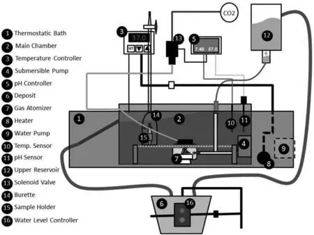
Fig.1.Schematic image of the hydrogen evolution setup.
A special setup [35] was designed to control temperature,pH,and flui fl w rate to simulate the human body environment.A pH controller module (Pro-Flora JBL) linked to a CO2gas cylinder was used to maintain the pH at 7.4 ± 0.1.The temperature was kept at (37.0 ± 0.5) °C during the test using a thermostat (Bunsen/TFB and MC-8).Furthermore,a continuous dripping system was used to circulate SBF with a proper fl w rate (2 mL/min/100 mL) [62].The SBF was injected into the corrosion cell using a hypodermic needle.
2.5.2.Hydrogen evolution experiments
Insulated fla specimens with an exposed area of ∼0.8 cm2were used to collect the hydrogen (H2) evolved during 15 days of immersion in SBF.In order to collect H2,6 specimens (for example,3 of BM + 3 of PEO) were placed inside of 6 inverted 25 mL burettes immersed into a plastic chamber containing 8 L of SBF,connected with the 9 L deposit.The chamber was placed into a thermostatic water bath with a constant temperature of (37±1) °C,as shown in Fig.1.An additional empty burette was also employed as a blank reference.A 6 W submersible water pump was used to agitate the SBF.A smart dripping system was used to inject the SBF into the chamber at suitable fl w rate.A CO2-based pH controller circuit was used to stabilize the pH at 7.4 ± 0.1.The H2vol was recorded every 15 min during the firs hour,every hour during 8 h (10 am to 6 pm) for the firs 3 days,and subsequently,twice a day.

Fig.2.3D optical micrograph of the microstructure of the AZ31B Mg alloy.
It should be mentioned that relatively high solubility of H2gas in water (1.4 mg/L at 37 °C) leads to dissolution of the generated hydrogen in ∼17 L of SBF before the partial pressure becomes sufficien to displace SBF in the burette.Hence,the“collected hydrogen”term is used instead of the“degradation rate” throughout the discussion,and it has been mainly used to emphasize the anti-corrosion performance comparisons between the coatings.

Fig.3.Voltage-time response for the PEO processes.
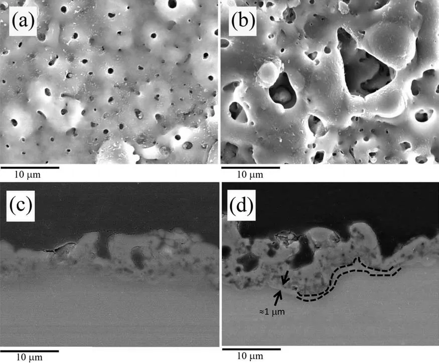
Fig.4.(a) Surface SEM micrograph of the PEO coating.(b) Surface SEM micrograph of the PCT coating.(c) Cross-sectional SEM micrograph of the PEO specimen.(d) Cross-sectional SEM micrograph of the PCT specimen.
3.Results and discussion
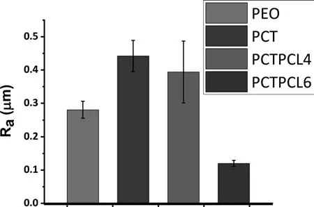
Fig.5.The surface roughness (Ra) of the PEO [35],PCT [35],PCTPCL4,and PCTPCL6 specimens.
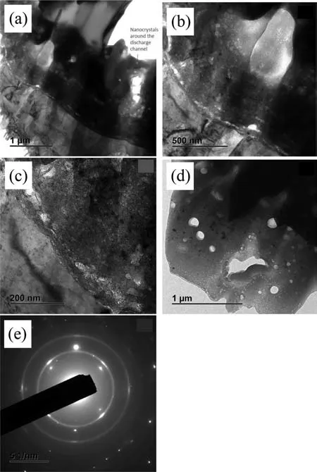
Fig.6.(a-d) TEM micrographs of the PEO coating acquired at 100 kV;(d) intermediate region of the coating;(e) electron diffraction pattern of the barrier region as seen in (c).
3.1.Base alloy characterization
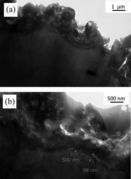
Fig.7.TEM micrographs of the PCT coating acquired at 200 kV.
Fig.2 exhibits the reconstructed 3D microstructure of the base alloy.Plastic deformation of Mg alloys during processing is limited to mechanical twinning and a few dislocation slip systems due to their hexagonal closed-packed (HCP) crystallographic structure [63].As a result,the base alloy shows a combination of fin and coarse grains accompanied by mechanical twins (Fig.2).Intermetallic particles are also observed.Results (at.%) of the EDS analysis (i.e.,Mg: 63.02%,Al: 30.06%,Mn: 6.7%,Fe: 0.21%) show that the intermetallic particles are composed of Al,Mn,and trace amounts of Fe.Based on the previous studies,the chemical composition of intermetallic particles is Al19Mn4[64].The side faces of the AZ31B Mg alloy rolled sheet (parallel and perpendicular to the rolling direction) reveal aligned and heavily deformed grains,which is a common feature of this type of products.Al-Mn intermetallic particles with slightly elongated shapes are also visible.
It should be noted that microstructural differences between the surface and the side faces can induce galvanic couples with a significan effect on the general corrosion behavior of the alloy [65].That is why orthopedic implants are typically extracted from extruded cylindrical bars that show a uniform microstructure.In any case,Mg wrought alloys tend to show strong textures regardless of the processing method.In the present study,the side faces of the specimens were insulated with an epoxy resin to study the response of the top surface.
3.2.Voltage-time curves
Voltage-time responses for the studied anodizing treatments are presented in Fig.3.During the firs seconds,thickening of the barrier layer occurs,resulting in a linear increase in voltage [66].Due to dielectric breakdown,there is a change in the slope at around 220 V and 235 V for PEO and PCT coatings,respectively.The presence of MWCNTs in the electrolyte postpones the onset of dielectric breakdown.MWCNTs possess negative zeta potential in silicatebased electrolytes(−0.6 mV at pH 13[67]).As a result,there is a electrophoretic motion of negatively charged MWCNTs towards the oxide/electrolyte interface during the anodic cycle.This phenomenon may eventually lead to their adsorption onto the growing barrier layer,thus modifying its mechanical and physical properties.The exact mechanism by which MWCNTs increase the dielectric strength of the barrier layer is unknown.It could be related to the high melting point and strength of MWCNTs [68–70] or other phenomena such as C doping of the MgO layer.
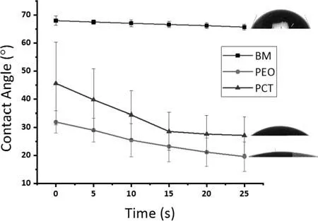
Fig.8.Variation of the contact angle with time for the BM,PEO,and PCT specimens.
3.3.Characterization of the peo and pct coatings
Plan-view SEM micrographs of the PEO and PCT coatings formed at 600 s are shown in Fig.4(a) and (b).the PCT coating contains larger pores in comparison.This is translated into a higher surface roughness (PEO: Ra0.281±0.025 μm,PCT: Ra0.442±0.047 μm) [35] (Fig.5).This has been associated with the presence of MWCNTs in the coating structure and in the electrolyte that enhanced the heat transfer [23,71].Accordingly,it would be expected that the molten oxide material in the PCT coating cools down faster,resulting in an open structure with visible pores.In contrast,the molten material in the PEO coating fill up the pores and produces the typical pancake-like structure after solidificatio is complete[35].Previously,the Authors have shown that MWCNTs with relatively intact morphology are only present in the superficia layer of the coating [35] because of their entrapment in the softened oxide material during the cooling stage of the discharge channels.During the micro-discharge,the MWCNTs are mostly disintegrated,and their presence in the coating manifested as high carbon content.
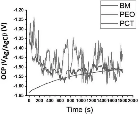
Fig.9.Open circuit potential (OCP) vs.time recorded for the BM,PEO,and PCT specimens in the quasi-in vivo environment.
Coating porosity plays two opposite roles in biomedical applications.Pores facilitate cell adhesion and cell proliferation[72],but they also provide paths for the corrosive medium to the substrate.However,it is known that the corrosion protection provided by the PEO coatings mainly depends on the corrosion resistance of the inner barrier layer.Cross-sectional backscattered electron micrographs disclose that both coatings feature a prominent barrier layer (Figs.4(c) and (d)),which appears thicker in the PCT coating (further confirme by the following TEM examination in Figs.6 and 7).This is consistent with the higher RMS voltage value observed for the PCT coating.Therefore,despite its larger pores,the PCT coating is expected to be more resistant than the PEO coating.
TEM examination of the PEO coating (Fig.6(a) shows approximately 20–25% of the inner part of the coating.Note the trail of nanocrystals around the large pore that appears to be a part of a discharge channel.Nanocrystals appear to be a common feature in otherwise amorphous matrix of the intermediate region of the coating(Fig.6(d)).The areas around the discharge channels are the hottest and cool slowly,so there is time for crystallization.A closer look at the ∼500 nm-thick barrier regions (Figs.6(b,c)) reveals a duplex morphology comprising a ∼20–30 nm-thick sublayer adjacent to the substrate and a thick top sublayer.It is evident that large pores are located just above the thick sublayer;in fact,they delimit the upper interface of the barrier layer.It is also evident that right under the large pores,the barrier layer/substrate interface is curving (Fig.6(a,b)),which means that these pores represent the bottom of the discharge channels.The barrier layer hence forms by a conventional anodizing mechanism after the plasma micro-discharge is extinguished.Given that the amplitude of the positive pulse is 405 V,the oxide growth rate stands to be ∼1.23 nm/V.
Both sublayers of the barrier region are polycrystalline,as evidenced by nanocrystals seen in the micrographs and by the selected area electron diffraction pattern (Fig.6(e)).A nearly continuous pore band that is formed due to oxidation of O2−species separates these sublayers.The oxidation process is facilitated on a crystalline oxide material,which is a better electron conductor than an amorphous oxide.This oxidation is likely facilitated by Zn enrichment in the film as evidenced by EDS analysis (Table 1).Despite the negligible amount of Zn in terms of at.% (which is related to the semi-quantitative nature of the EDS analysis),Zn peak is quite prominent in the spectra (Supplementary Figure 2).This is consistent with previous finding of Arrabal et al.[73].The polycrystallinity of the inner region of the coating is expected to have implications for corrosion resistance: nanocrystals are defects that conduct electrons for the cathodic reaction.

Table 1 EDS analysis of the barrier and intermediate coating regions as seen in Fig.6(c) and (d),respectively.

Table 2 Fitted parameters of the equivalent circuits for the BM,PEO,and PCT specimens.
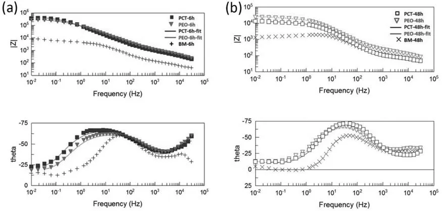
Fig.10.Bode and phase plots of the BM,PEO,and PCT specimens after 6 h (a) and 48 h (b) immersion in quasi-in vivo environment.

Fig.11.Equivalent circuits proposed for (a) the PEO and PCT specimen after 6 h immersion,(b) the PEO and PCT specimens after 48 h immersion.(Rs:Solution resistance,Rout: Resistance of outer porous layer Rin: Resistance of inner barrier layer,Rp: Polarization resistance,Wcp: Warburg element (finit length,short terminus) corresponding to the diffusion through corrosion products,CPEout: Constant phase element of the outer porous layer,CPEin: Constant phase element of the inner barrier layer,CPEdl: Constant phase element of the electrical double layer.).
The TEM micrographs of the PCT coating (Fig.7) also reveal a stratifie ∼500 nm-thick barrier region.However,its inner sublayer is much thicker (∼100 nm) than that of the PEO coating (∼30 nm).Therefore,better corrosion resistance can be reasonably expected from the PCT coating,despite the larger pores,due to its thicker inner barrier sublayer.
Poor coating adhesion is a concern in biomedical applications since third-body abrasion by coating debris compromises the integrity of the implant contact surfaces.This is a significant challenge for coatings produced by non-reactive processes such as thermal spraying.However,in case of plasma electrolytic oxidation,this should not be an issue due to the intimate bonding at the substrate/coating interface.Accordingly,the adhesion strength is expected to be higher than the cohesion strength.Experiments carried out in this work (not shown) confirme this,with the obtained cohesion strengths values being (8.5 ± 0.9) MPa and (7.3 ± 0.4) MPa for the PEO and PCT coatings,respectively.The slightly lower cohesion strength of the PCT coating is attributed to its larger pores.Note that these values are relatively high in comparison to those reported in other studies [74].
The wettability of a biomedical coating is another parameter that should be investigated.On the one hand,a higher wettability (i.e.,hydrophilicity) allows living cells to adhere to the surface and proliferate easier [75].On the other hand,hydrophilic coatings are more susceptible to corrosion attack due to faster penetration of aggressive species towards the coating/substrate interface.Fig.8 presents the evolutions of wetting angle values for the BM,PEO,and PCT.The wetting angle of BM remained relatively constant during the evaluated period,whereas it decreased for the PEO and PCT specimens.Despite its larger pores and higher surface roughness,it is evident that the PCT coating is slightly less hydrophilic.This can be attributed to the presence of trapped MWCNTs inside of the coating pores and to the different composition of the outer layer.The PCT coating is constituted by MgO and Mg2SiO4,whereas the PEO specimen is composed of MgO and a higher amount of P [76].It is also interesting to note that the wetting angle of the PCT specimen tends to stabilize by the end of the testing period,while it keeps decreasing for the PEO coating,suggesting an increased water uptake.

Fig.12.SEM cross-section and plan views of the PCTPCL4 ((a),(c)) and PCTPCL6 ((b),(d)) specimens.
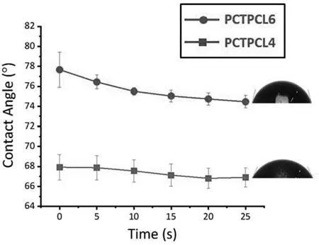
Fig.13.Variation of the contact angle with time for the PCTPCL4 and PCTPCL6 specimens.
3.4.Electrochemical measurements
OCP-time curves of the BM,PEO,and PCT specimens are presented in Fig.9.The OCP of BM increased from −1.63 VAg/AgClto −1.5 VAg/AgClafter 30 min of immersion.This is associated with the growth of a layer of corrosion products [77].Coated specimens showed higher OCPs (∼−1.35 VAg/AgCl) at the early stages of the immersion,but decreased to −1.55 VAg/AgClby the end of the experiment due to phenomena such as hydration of the thermodynamically unstable phases [35].Note that OCP oscillations in the PCT coating were less pronounced,possibly due to the presence of the highly stable Mg2SiO4and the better corrosion protection provided by the thicker barrier layer (Fig.7(b)) [35].The role of MWCNTs as nano-traps for Cl−ions could also be related to the higher stability of the OCP [78].

Fig.14.(a) Collected generated hydrogen by the BM,PEO,PCT,PCTPCL4,and PCTPCL6 specimens within 15 days of immersion in quasi-in vivo environment;(b) Collected generated hydrogen by the PEO,PCT specimens within 15 days of immersion in quasi-in vivo environment.(c) Collected generated hydrogen by the PCTPCL4,PCTPCL6 specimens within 15 days of immersion in the quasi-in vivo environment.
The impedance spectra (Bode and phase plots) of the BM,PEO,and PCT specimens are exhibited in Fig.10.Owing to the corrosion products layer formed on the BM during immersion,two overlapping relaxation times corresponding to the corrosion layer (high frequency) and electrical double layer(low frequency) can be seen [79,80].After 48 h of immersion,a pseudo-inductive behavior is observed (Fig.10).This is a common feature of magnesium alloys that have undergone significan localized corrosion and is probably the result of non-stationary conditions during the electrochemical measurement [81].Another possible explanation is the adsorption of species such as Mg(OH)+adsand Mg(OH)2ads[82].The corrosion resistance reduction of the BM after 48 h is evident;|Z|10mHz= 6600Ωcm2and |Z|10mHz= 1688Ωcm2after 6 h and 48 h of immersion,respectively.
Fitting of the EIS data of the PEO and PCT specimens after 6 h immersion was carried out according to the equivalent circuit in Fig.11(a) [82,83].This circuit includes elements representing the electrochemical response of the outer porous(Rout/CPEout) and inner regions (Rin/CPEinand Rb/CPEb) of the coatings.
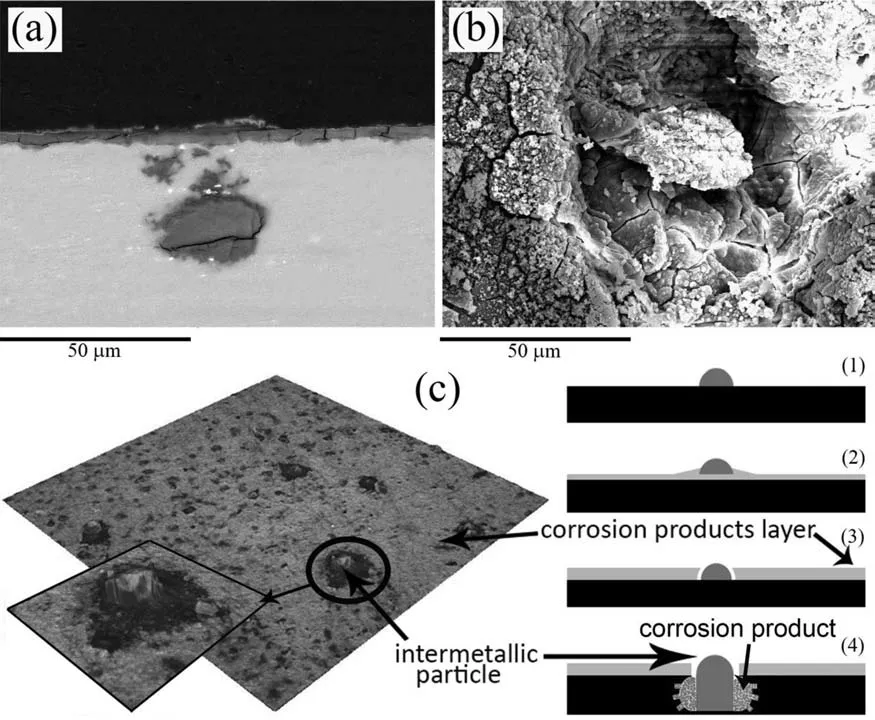
Fig.15.Cross-sectional (a),and plan view (b),SEM micrographs of the BM specimen after 5 days of immersion in quasi-in vivo environment.(c) Schematic possible mechanism of formation and growth of the pits surrounding the intermetallic particles.
As shown in Table 2,for the PEO specimen,Rout(845.8Ωcm2) is much lower than Rin(297,090Ωcm2),demonstrating that the barrier layer is the main factor responsible for the anti-corrosion properties of the coating.A similar result is observed for the PCT specimen (Rout996.4Ωcm2;Rin467,420Ωcm2).As expected,Rinis higher for the PCT specimen due to formation of a thicker barrier layer (Fig.7(b)).Routvalues are relatively similar for the PEO and PCT specimens,despite of the bigger pores formed in the presence of MWCNTs.This may be due to the presence of MWCNTs inside the pores,preventing diffusion of the aggressive species.Comparison of the CPEoutcorresponding to the PEO and PCT specimens also demonstrates a higher value for the latter.This can be attributed to the presence of MWCNTs,which are known to behave as electrochemical capacitors due to their special symmetry and unique electronic structure[84].Furthermore,lower CPEinof the PCT can be ascribed to the higher thickness of its inner barrier layer.Notably,the exponents (n) corresponding to the PEO and PCT are 0.71 and 0.77,respectively,indicating non-ideal capacitive behavior of the inner barrier layer in both coatings.

Table 3 EDX data corresponding to the outer and inner regions of the PCT coating after 5 days of immersion in the quasi-in vivo environment.
The high Rinand Rbvalues suggest that the SBF did not reach the substrate after 6 h of immersion.Therefore,the Rbvalue after 6 h of immersion could be associated with the innermost region of the barrier layer.It is evident that the PCT coating (Rb273,250Ωcm2) provides higher protection against corrosion than the PEO coating (Rb151,000Ωcm2)due to a greater thickness of its inner barrier sublayer,as evidenced by TEM (Fig.7).
After 48 h of immersion in quasi-in vivoconditions,both coatings deteriorated remarkably;therefore,the equivalent circuits were changed accordingly.A diffusive Warburg element,that replaced Rin,was attributed to partial failure of the barrier layer and local alkalization inside of the pores.The formation of the corrosion products inside the pores impedes the mass transport of species in the solution (Fig.11(b)).The Rp/CPEdlterms after 48 h represent the response of the substrate/electrolyte interface at the sites of local coating failure.Degradation of the coatings is mainly reflecte by the lower Routand Rpvalues for both coatings.The PCT showed a more significan loss of the outer layer resistance,possibly due to its larger pores.
The higher W-T value for the PCT indicates a longer diffusion path through the corrosion products in the inner region of the coating.Comparison of the Rpand W-R reveals that diffusive impedance of the PEO and PCT coatings is responsible for corrosion protection after 48 h immersion in the quasi-in vivoenvironment.In summary,despite the initial better corrosion resistance of the PCT coating,with time,it gradually approaches the electrochemical response of the PEO coating.
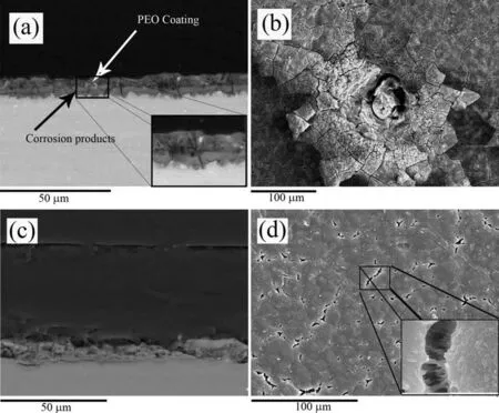
Fig.16.Cross-sectional and plan view SEM micrographs of the PEO (a),(b) and PCTPCL6 (c),(d) specimens after 5 days of immersion in quasi-in vivo environment.
3.5.Characterization of duplex PCT/PCL coatings
Good adhesion and adequate corrosion and wear protection are fundamental prerequisites for any coating for implant materials.Open porosity and high wettability are also desirable if top-layers are applied.However,any coating system designed for biodegradable implants should eventually dissolve.Characterization and corrosion testing performed in this study and the wear results obtained in [35] evidence that the addition of MWCNTs affects the surface properties of the PEO coatings: the roughness increases,hydrophilicity is maintained,and corrosion and wear resistances are improved.A rougher surface (i.e.,PCT) increases the interaction surface area between a polymer topcoat and ceramic under-layer.Therefore,the PCT coating was considered as a better under-layer for duplex coating systems that used PCL top-layers (either thin or thick).
The measured thicknesses of the polymeric coatings on top of the PCTPCL4 and PCTPCL6 treated specimens are∼2 and ∼60 μm,respectively (Fig.12 (a,b)).The surface topography (Fig.12(c,d))of the PCTPCL4(Ra0.394±0.093 μm) follows the roughness pattern of the underlying ceramic coating (Ra0.442±0.047 μm,Fig.5).The roughness of the thick PCTPCL6 (Ra0.115±0.0093 μm) seems to be unaffected by the underlying topography.The adhesion strengths of the PCTPCL4 and PCTPCl6 to the PCT under-layer were(4.5 ± 0.4) MPa and (4.5 ± 0.3) MPa,respectively,so there was no meaningful statistical difference between the obtained values.
Fig.13 depicts the wetting angle variations of the PCTPCL4 and PCTPCL6 specimens.Contrary to the stand-alone porous ceramic coating,no significan changes in the measured values are observed.The average values of wetting angles of the PCTPCL4 and PCTPCL6 are 67° and 77°,respectively.This difference can be related to the different surface roughness based on the Wenzel equation [85].Higher surface roughness corresponds to higher contact surface area with the water droplet,and subsequently,higher surface energy.That is why the average wetting angle of the PCTPCL4 is lower than that of PCTPCL6.Accordingly,the PCTPCL4 is expected to be more biocompatible,but likely more permeable,in comparison to the PCTPCL6.
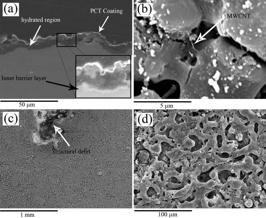
Fig.17.Cross-sectional (a) and plan view (b,c,d) SEM micrographs of the PCT specimen after 5 days of immersion in the quasi-in vivo environment.
3.7.Hydrogen evolution
The results of H2evolution experiments for the BM,PEO,PCT,PCTPCL4,and PCTPCL6 specimens under quasi-in vivoconditions are plotted in Fig.14(a).As it can be seen,the slope of the curve corresponding to the BM specimen remains relatively constant during the testing period.This behavior is opposite to what is typically found in conventional studies,where the corrosion rate decreases with time due to increasing pH values and subsequent passivation of the surface [86,87].Therefore,the buffering system used in the current study is more representative ofin vivoconditions,where local alkalization is counteracted by the constant fl w of the medium surrounding the implant.
Characterization of the corroded BM specimen after 5 days of immersion (Fig.15(a) and EDS ((at%): 27.48% C,37.86%O,17.93% Mg,1.73% Al,7.53% P,1.63% Cl,5.16% Ca,0.68% Zn) shows a ∼7 μm-thick layer comprising corrosion products and sediments from SBF.The latter would include phosphates and carbonates (CaCO3and MgCO3) that have been reported in other studies in which CO2/HCO3−buffering system had been used[88,89].Furthermore,some isolated pits form at the locations of intermetallic particles.Note that the cross-section in Fig.15(a) does not pass through the central axis of the pit,and the pit itself appears to be of irregular shape,which results in discontinuity of the observed corroded area.The activity of the galvanic couples formed between the intermetallic particles (cathodes) and the matrix (anode)[64] also results in some local thickening of the corrosion layer (Fig.15(b)).At a later stage of immersion,the thick layer surrounding the intermetallic particle starts to crack,and a pit initiates.Subsequently,the initiated pit starts to grow towards the substrate.As it can be seen,the pit is fille up with corrosion products.The suggested mechanism along with a plan view optical image of the corroded surface is given in Fig.15(c).

Fig.18.Plan view SEM micrographs (a,b,c),and a macrograph (d) of the PCTPCL4 specimen after 5 days immersion in the quasi-in vivo environment.
The total hydrogen evolved from the PEO and PCT specimens after 15 days of immersion was reduced by 74% and 91%,respectively,compared to the BM specimen(Fig.14(a)).According to TEM examination and EIS analysis,this improved corrosion performance is mainly attributed to the inner barrier layer and,to a lesser extent,to the outer porous layer.It is worth noting that both specimens show a change in corrosion rate after approximately 200–250 h of immersion.This change occurs faster in the PEO specimen,suggesting an earlier failure of the barrier layer.This is to be expected for stand-alone coatings since the barrier layer is mainly composed of MgO that is not stable in the neutral SBF.
SEM examination of the PEO specimen after 5 days immersion shows both uniform undercoating corrosion(Fig.14(a) and (a)-inset) and corrosion pits (Fig.14(b)).In case of the PCT specimen (Fig.15),the pits were less numerous and no signs of undercoating corrosion were observed,though coating hydration was evident.This latter feature is sometimes observed in the PEO coatings on Mg because the inner region is rich in MgO and,therefore,more susceptible to hydration than the Si- and P-rich outer layer [81].The inner region is mainly composed of hydrated coating material and SBF-induced deposits (Table 3).It should also be noted that,the hydration is associated with a volume expansion and increasing stresses that may induce cracking of the coating (Fig.16(a) and (b)) [90].However,the incorporated MWCNTs (Fig.17(b)) seem to delay crack propagation via a bridging mechanism [91],resulting in an almost intact outer layer (Fig.17(d)).The inner barrier layer tends to remain unaffected until the end of the hydration stage (Fig.17(a),inset)).Fig.17(c) shows a big structural defect that possibly bears the main responsibility for the hydrogen generation in the PCT specimen.This weak site might have been created during the coating formation process because of an intense micro-discharge.At sites like this,the oxide morphology is typical of that of thermal oxidation and has inferior protective properties [92].Therefore,a galvanic couple may form between a structural defect (Fig.17(c)) and intact zones(Fig.17(a)),and lead to the progressive growth of the structural defect during the immersion period.
The marked difference in the amount of hydrogen generated by the PCTPCL4 and PCTPCL6 specimens during 15 days of immersion (Fig.14(c)) can be explained as follows.The surface SEM micrographs and a macrograph of the PCTPCL4 (Fig.18) reveal non-uniformity of its PCL layer across the specimen surface.Two different regions are disclosed: the center of the specimen with a thicker coating and the edge with a thinner PCL coating.This heterogeneity has resulted from the dip-coating process.Where the polymer solution runs off the edges,the layer is consequently thinner compared to the central area.Within 5 days of immersion,the coating layer at the edge region has degraded significantl ,and the underlying ceramic coating (PCT) has been consequently exposed to the corrosive solution.Accordingly,the greater corrosion rate of the PCTPCL4 specimen (Fig.14(c))could be a result of a competition between two opposing factors.On one hand,the surface area that generates hydrogen has been reduced almost by half (since PCL sealing layer still holds on in the central region of the specimen) compared to the PCT specimen.On the other hand,the central region and the peripheral region may have established a galvanic couple,which would promote the corrosion rate of the anode (the edges).Nevertheless,the PCTPCL4 specimen still has shown 15% less hydrogen generation than the PCT specimen.
The PCTPCL6 specimen showed the lowest amount of measured hydrogen in 15 days of immersion.After 5 days of immersion,the cohesion at the PCL/PCT interface begins to appear compromised (Fig.18(d)),although no corrosion products have yet been formed at the substrate/PCT interface.During long-term immersion time,these defects would expand and allow the solution to penetrate through the PCT layer and ultimately breach the inner barrier MgO layer of the PCT.
4.Conclusions
The following may be inferred from the findings
•The BM shows a linear degradation behavior in quasiin vivoconditions,with Al-Mn-Fe intermetallic particles playing a determining role in the localized corrosion process.
•The lower cohesion strength of the PCT in comparison to PEO is attributed to the larger pores of the PCT coating.
•The presence of the MWCNTs inside the pores and in the superficia layer of the PCT coating has reduced its hydrophilicity.
•Undercoating corrosion,accumulation of the corrosion products,and subsequent induced stress are responsible for pitting corrosion occurrence in the PEO specimens.
•The enhanced barrier layer of the PCT delays the onset of undercoating corrosion by at least 48 h;until then,the degradation proceeds by diffusion-controlled coating hydration.The subsequent increase in generated hydrogen is mainly due to structural defects in the coating induced by intense micro-discharges during the PCT coating growth.
•Sealing with a thin PCL layer leads to a 15% of improvement in corrosion resistance in comparison to the PCT based on H2collection during immersion in SBF.
•The thick hybrid PCTPCL6 coating leads to an 85% reduction in collected hydrogen (in comparison to PCT) and delays the onset of undercoating corrosion by at least 120 h in the quasi-in vivoenvironment.
Declaration of Competing Interest
The authors declare that they have no known competing financia interests or personal relationships that could have appeared to influenc the work reported in this paper.
Acknowledgments
The authors gratefully acknowledge the financia support of the Iran National Science Foundation INSF (Grant No.97014179).This work was also supported by RTI2018–096391-B-C33 (MCIU/AEI/FEDER,UE) and S2018/NMT-4411 (Regional government of Madrid and EU Structural and Social Funds).M.Mohedano is grateful for the support of RYC-2017–21843.We also gratefully acknowledge financia support from the Spanish National Science Foundation(CSIC)and the Ministerio de Ciencia,Innovación y Universidades(MINECO) grant number RTI2018–096328-B-I00.The technical support from Dr.Mariona Cabero during the preparation of TEM cross-section specimens is gratefully acknowledged.
Supplementary materials
Supplementary material associated with this article can be found,in the online version,at doi:10.1016/j.jma.2021.09.010.
杂志排行
Journal of Magnesium and Alloys的其它文章
- Grain refinemen of Mg-alloys by native MgO particles: An overview
- Tailoring MgH2 for hydrogen storage through nanoengineering and catalysis
- In silico studies of magnesium-based implants: A review of the current stage and challenges
- Investigating local corrosion processes of magnesium alloys with scanning probe electrochemical techniques: A review
- A tightly bonded reduced graphene oxide coating on magnesium alloy with photothermal effect for tumor therapy
- Nucleation of recrystallization in magnesium alloy grains of varied orientation and the impacts on texture evolution
