Investigating local corrosion processes of magnesium alloys with scanning probe electrochemical techniques: A review
2022-12-30MrCristinLopesdeOliveirRejneMriPereirSilvRirdoSoutoRentoAltoelliAntunes
Mr Cristin Lopes de Oliveir,Rejne Mri Pereir d Silv,Rirdo M.Souto,Rento Altoelli Antunes,∗
a Federal University of ABC,Center for Engineering,Modeling and Applied Social Sciences,Av.Dos Estados,5001 09210-580,Santo André SP Brazil
b Instituto de Pesquisas Energéticas e Nucleares,IPEN/CNEN,Av.Prof.Lineu Prestes,2242,São Paulo,Brazil
c Institute of Material Science and Nanotechnology,University of La Laguna,P.O.Box 456,La Laguna,Tenerife 38200,Spain
Abstract The study of corrosion of magnesium and its alloys has emerged a hot topic in the applications of lightweight structural materials.The inherently high electrochemical activity of bare magnesium surfaces still lacks a convincing mechanism to describe the observed experimental characteristics,and it has prompted the development of various types of protective coatings with the aim of slowing metal dissolution.In recent years,new instruments and techniques have been developed to study with spatial resolution the local corrosion processes that occur in metallic materials in general,and for magnesium and its alloys in particular,both for bare surfaces and coated.Scanning microelectrochemical techniques,such as local electrochemical impedance spectroscopy (LEIS),scanning electrochemical microscopy (SECM),scanning vibrating electrode technique (SVET),scanning ion-selective electrode technique (SIET) and scanning Kelvin probe (SKP) can provide information about the local electrochemical activity of metallic surfaces.In the present work,the applications of these techniques in corrosion studies of magnesium and its alloys are reviewed.Assessment of corrosion mechanisms,barrier properties of conventional coatings and active corrosion behavior of self-healing coatings are examined.Limitations and future developments in this area are discussed.
Keywords: Magnesium alloys;LEIS;SECM;SVET;SIET;SKP.
1.Introduction
As contemporary demands for the use of lightweight materials in the automotive and aerospace industries have steadily increased over the past decade due to environmental concerns and legislative restrictions worldwide,magnesium alloys attract much interest for structural applications [1–3].However,the strategic role played by these materials in lightweight structural usages is largely undermined by their well-known high electrochemical activity [4,5].In fact,susceptibility to corrosion is the main limitation to the widespread use of magnesium alloys [6,7].It is generally accepted that this poor resistance to corrosion in an aqueous environment compared to other lightweight alloys,such as aluminum,is due to the formation of a non-protective oxide/hydroxide layer on the surface [8].Even though spontaneous corrosion of magnesium-based materials is considered advantageous for producing bioresorbable implant devices for healthcare applications [9,10],the uncontrolled dissolution of the materials which is accompanied by the vigorous release of potentially tissue-damaging hydrogen gas (eventually leading to gas embolism in extreme cases [10]),makes corrosion the main concern and limitation of their wide biomedical use.
The need for improving or controlling the corrosion resistance of magnesium alloys has triggered the development of several protection methods based on alloying,microstructural control (grain size,crystallographic texture),and,especially,the application of protective coatings[11–15].A huge amount of research has been devoted to exploring different strategies of enhancing the corrosion resistance of magnesium and its alloys [16–20].
In spite of the knowledge accumulated so far on the corrosion mechanisms of magnesium alloys,several questions remain unclear.Complex interactions between microstructural aspects such as grain size,distribution of intermetallics,impurity dissolution and redeposition,alloying elements and environmental conditions may take place [21–23].Exploring such phenomena to gain full understanding on the corrosion processes,especially at localized sites,is a challenging situation [24].As highlighted by Esmaily et al.[17],scanning probe electrochemical techniques are potentially useful for studying local corrosion processes of magnesium and its alloys,allowing one to investigate pitting,galvanic,intergranular or mechanically assisted corrosion.Furthermore,failure of protective film can also be studied using this type of techniques,giving valuable information about the correlation between deposition parameters and the corrosion behavior of the coated substrates,as well as self-healing mechanisms of smart protective coatings.Techniques such as scanning electrochemical microscopy(SECM),scanning vibrating electrode(SVET),localized electrochemical impedance spectroscopy(LEIS),scanning Kelvin probe (SKP),and scanning micropotentiometric methods (usually referred to as potentiometric SECM or ion-selective electrode technique,SIET) have been recently introduced to study local corrosion processes of magnesium alloys,either coated or not [25–29].Their high spatial resolution is an attractive feature to study local corrosion spots in metallic materials [30–32].
As the use of novel methods to study local corrosion processes of magnesium alloys becomes more widespread,new insights into corrosion mechanisms and effective protective coatings are becoming available in the literature.However,a comprehensive review of the potential applications of scanning probe electrochemical techniques to study the corrosion processes of magnesium and its alloys has yet to be found.The aim of the present work is to fil this gap.We provide a thorough review of the current literature on the use of SECM,SVET,SIET,SKP and LEIS to investigate the local electrochemical activity of magnesium and its alloys.A detailed evaluation of the corrosion mechanisms is carried out for either bare or coated substrates.Future research directions in this area will also be discussed.
2.A brief outlook on magnesium corrosion
This review is not intended to provide full details on the corrosion mechanism of magnesium alloys in aqueous environments,as such information can be found in authoritative reviews such as those published by Esmaily et al.[17],Yang et al.[33] and Ghali et al.[34].However,fundamentals of magnesium corrosion are important to support discussion in the next sections.Hence,some core points regarding corrosion mechanisms of magnesium alloys will be briefl described in this Section.

Fig.1.Hydrogen evolution rate increasing with the applied current density for several Mg alloys in 0.1 M NaCl or 0.1 M Na2SO4 solutions.Reprinted with permission from Elsevier [36].
Although the exact mechanism that explains the corrosion of magnesium in an aqueous environment is not fully understood and remains controversial,it can be summarized using Eq.(1),which in turn can be uncoupled in the anodic and cathodic reactions shown in Eqs.(2) and (3),respectively [35].Magnesium cations are formed at the anodic sites,while hydrogen gas is released at the cathodic sites.

(overall reaction)

(anodic reaction)

(cathodic reaction)
Besides the known formation of hydrogen gas that occurs on the surface of magnesium in open circuit conditions (reaction 1),an anomalous evolution of hydrogen occurs when the metal is anodically polarized.This effect can be seen in Fig.1 for anodically polarized pure Mg,Mg-Zn-Ca-Mn alloy,and Mg-Y alloy in 0.1 M NaCl and 0.1 M Na2SO4solutions[36].The acceleration of the cathodic reaction rate when magnesium is subjected to anodic polarization contradicts the traditional theory of corrosion kinetics controlled by Butler-Volmer activation.The explanation for this phenomenon remains controversial in the literature,although significan contributions from several authors have pointed to a complex scenario involving different and even contradictory processes in the surface such as the possible release of short-lived intermediate anodic species (e.g.the elusive unipositive Mg+),the controversial role of impurities that may lead to metal dissolution and redeposition,and the precipitation of corrosion products (MgO/Mg(OH)2) with certain electrochemical activity.In this context,scanning probe techniques can be expected to provide valuable information to elucidate the mechanisms involved in this process [37].
The presence of intermetallic particles(IMPs)also plays an additional and important effect on the corrosion behavior of magnesium alloys [38].The central aspects of the influenc of IMPs are related to their quantity,their distribution and their electrochemical activity (i.e.,cathodic or anodic character with respect to the magnesium matrix) [39].In this sense,IMPs can slow down the corrosion rate by forming a continuous network or act as a galvanic cathode,thus accelerating the corrosion rate of the matrix [40,41].However,they can also act as microanodes,dissolving preferentially instead of theα-Mg matrix [42].Several commercial magnesium alloys present IMPs in their microstructures,such as those containing Al,Zn,rare earth (RE) elements (namely Y,Nd,Ce,La)and Ca as alloying elements.Common intermetallic phases are Mg17Al12,Mg2Ca,Mg12Ce,Mg12La,Mg3Nd,Mg24Y5,Mg3Al2,and MgZn2[43].
3.Fundamentals of scanning probe electrochemical techniques
Before reviewing the literature on the use of scanning probe techniques to study the local corrosion processes of magnesium and its alloys,fundamental aspects of the main local microelectrochemical techniques are described in the present section.This is intended to serve as a basis for a full understanding of the results discussed in the next section.
3.1.SECM
Scanning electrochemical microscopy (SECM) employs a polarizable ultra-microelectrode (UME),effectively polarized in its double-layer charging range,which very frequently consists of platinum wire encapsulated in a glass capillary[44,45].In this way,faradaic currents fl wing through the tip are measured while scanning a surface under study.A positioning system is responsible for the movement of the UME over the sample surface,fi ed at a specifi height.Reference and counter electrodes are also part of the electrochemical cell.The system is completed with a bipotentiostat that enables controlling potentials and/or currents at the UME or the sample surface [44].A schematic representation of the instrumental arrangement is shown in Fig.2[46].Various operation modes are available in SECM.In the feedback mode,a redox mediator must be added to the electrolyte solution to monitor how proximity to the investigated sample affects the rate of its redox conversion at the UME.Depending on whether the substrate is insulating or conductive,it can experience negative or positive feedback,respectively.For insulating surfaces,the current passing through the UME for the redox conversion of the electroactive species (i.e.,the redox mediator) decreases due to geometric hindrance to its diffusion,causing a negative feedback effect.The opposite occurs when current passes through the surface of a conductive material,as it can promote regeneration of the redox mediator on the sample and cause an increase in current in the UME called positive feedback [44].Although the feedback mode is usually performed while the studied substrate is polarized using the bipotentiostat,this is not necessary in the case of a spontaneously corroding system.That is,electron transfer reactions can occur at the substrate under open circuit conditions.In this context,substrate polarization remains as an option rather than as a requirement.Another operation mode is substrate generation-tip collection (SG-TC) in which the tip detects an ionic species formed during substrate corrosion at a selected potential [44,47].When the electroactive species is generated at the tip and collected at the substrate,the mode is called tip generation/substrate collection (TG/SC) [44,48].Thirdly,in the redox competition mode (RC),the substrate and the tip compete for the same redox species [49].A common example is the monitoring of dissolved oxygen concentration that indicate local spots where cathodic reactions involved in the corrosion of coated metals occur at defective sites in the coating layer [50,51].

Fig.2.Schematic representation of the SECM.Reproduced with permission from MDPI [46].
Another mode is to use an AC voltage to polarize the UME,which leads to the measurement of an alternating current signal at the UME.In this case,either a lock-in amplifie or a frequency response analyser (FRA) must be included in the instrument assembly as shown in Fig.2.An impedance value can be determined from the ratio between the applied voltage and the measured current.This mode of operation is usually referred to as AC-SECM [52],and has more recently evolved into the development of scanning electrochemical impedance microscopy (SEIM) [53].
3.2.SVET
SVET is a powerful technique in corrosion research,which is applied to a variety of investigations,such as galvanic corrosion,stress corrosion cracking,pitting corrosion,corrosion inhibitors,coated metals and weldment corrosion,as highlighted by Bastos et al.[54].The measurement principle of SVET is based on the movement of a vibrating electrode over the surface of an electrochemically-active substrate immersed in solution,measuring the current ionic density distributions arising from it [55].The probe consists of a thin platinum tip.A schematic illustration of the SVET system is shown in Fig.3 [56].In brief,the ionic current fl w generated by corrosion of the metallic electrode causes a potential gradient in the electrolyte at the active site.This potential gradient is detected by the SVET vibrating probe [54].The potential difference between two extreme points of the SVET probe is measured,generating a sinusoidal AC perturbation signal that is converted to ionic current density using a calibration procedure that takes into account the conductivity of the electrolytic solution [57].Due to the mechanical vibration of the probe,local convective effects are generated in the electrolyte which effectively imposes a minimum height limit over the sample for operation and,therefore,determines the spatial resolution of the technique [58].Izquierdo et al.[59] reported a performance comparison of SECM and SVET for imaging corrosion processes in galvanic couples.
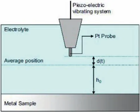
Fig.3.Schematic illustration of the SVET system.Reproduced with permission from Elsevier [56].
3.3.Scanning micropotentiometric methods
Scanning micropotentiometric methods (often called scanning ion electrode technique,SIET,or potentiometric SECM)are based on the detection of concentration distributions of a specifi chemical species present in an electrolyte solution using a passive microelectrode which measures potential changes through the surface of the electrode detection window (namely a membrane or a certain oxide layer) [60].Therefore,the electrochemical cell also contains a reference electrode which is held fi ed somewhere in the electrolyte as shown in Fig.4 [46].While only ion-selective microelectrodes(ISME)for either pH or other specifi ionic species are considered as probes in the case of SIET,certain metal oxides sensitive to changes in the environment are also employed in potentiometric SECM,like antimony and iridium for pH sensing [46].In the latter case,dual amperometric/potentiometric operation has also been achieved using these probes [61].

Fig.4.Schematic representation of the potentiometric SECM.Reproduced with permission from MDPI [46].
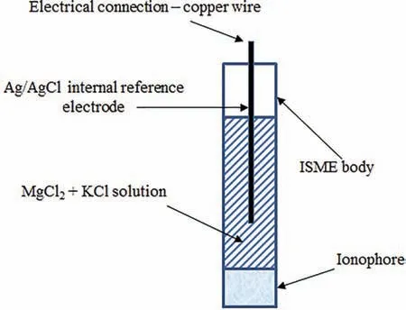
Fig.5.Schematics of the constituents of a Mg2+ ISME with liquid contact,and the processes taking place between the different active components in the system.The membrane sandwiched between the internal solution and the electrolyte supports Mg2+ ion transport and eventually attains an equilibrium potential (Donnan potential).The Donnan potential varies logarithmically with the Mg2+ ion concentration in the electrolyte and is sensed by the internal reference electrode.The internal reference when connected to an external reference electrode,immersed in the same electrolyte “senses” the Mg2+ ion concentration.Reprinted with permission from NACE [64].
Ion-selective microelectrodes (ISME) are usually comprised of a micropipette made of glass or plastic,containing ionophore to detect pH changes or ions at the electrode tip and a liquid electrolyte to provide electrical connectivity to an internal reference electrode [60,62,63].The operation principle of such liquid-contact (ISME) is schematically described in Fig.5 [64].Some limitations for conducting SIET studies are related to the fragile nature of the glass micropipettes,as well as their relatively short lifetime (typically one day) due to the blocking effect of corrosion products at the tip [32].As result,new designs are directed to generate an internal solid contact in the ISME leading to a more robust performance and improved response times due to smaller internal resistances [65].In addition,the use of an optode allows for the monitoring of dissolved oxygen with the same instrument,effectively revealing the reduction of this species during magnesium corrosion [66].For corrosion studies,SIET can be used in conjunction with SVET,as they provide complementary information on the corrosion processes [30].

Fig.6.Schematic representation of (a) the LEIS configuratio and (b) the two-microelectrode probe.Reprinted with permission from Elsevier [67].
3.4.LEIS
The fundamental operation principle of localized electrochemical impedance spectroscopy (LEIS) is centered on the measurement of the local current density near the surface of electrochemical interface that is obtained from local potential difference between two microelectrodes [67,68] as shown in Fig.6.The local impedance is derived from the relationship between the applied voltage perturbation between working and reference electrodes and the local current density [69].Two operation modes are available.The firs one relies on the measurement of local impedance spectra taken at specifi sites over the sample surface.The other one is based on impedance mapping at a fi ed frequency as the LEIS probe is moved across the sample surface.Details on the LEIS experimental set-up can be found elsewhere [68].
3.5.SKP
As a non-destructive technique,Scanning Kelvin probe(SKP) is based on the movement of a metallic microelectrode probe (usually made of tungsten) over the surface of a conductive or non-conductive sample without contacting it.The work function difference between the probe and the sample is measured under humid air conditions,a unique feature of the SKP technique (a liquid electrolyte is not employed).The principle of the Volta potential measurement is displayed in Fig.7 [70].Fig.7a shows the schematic illustration of two different metals with distinct work functions (φ) put in contact,whereas the representation in Fig.7b displays the Fermi levels (EF) of each metals reaching equilibrium,making electrons to fl w from the lower work function metal (φsample) to the higher work function one (φprobe).On the other hand,in Fig.7c the Fermi level and the vacuum level (Evac) are lifted to their original positions upon the influenc of the applied potential (VCPD).The Volta potential difference between the probe and the working electrode is associated with the corrosion potential of the sample under investigation [71].Details on the fundamentals of the technique can be found in the report by Rossi et al.[56].There is also the possibility of using SKP coupled to an atomic force microscopy (AFM) instrument.The technique is known as SFPFM (scanning Kelvin probe force microscopy).In this technique,the topographic image of the scanned surface is acquired by the AFM tip,as well as the Volta potential at each point of the scanned region.Further details can be found in the review by Rohwerder and Turcu [72],who described the main features and differences of SKP and SKPFM.
4.Scanning probe techniques applied to corrosion studies of magnesium and its alloys
This section has been divided into two subsections to describe investigations using scanning probe techniques of the corrosion processes of magnesium and its alloys for uncoated and coated substrates.Various aspects on the use of these techniques will be reviewed.The aim is to provide the reader with a comprehensive overview of the capabilities and limitations of using scanning probe techniques to elucidate the corrosion mechanisms of these materials.
4.1.Uncoated surfaces
Table 1 lists a compilation of work devoted to the study of localized corrosion processes of uncoated magnesium surfaces using scanning probe techniques.The information will be organized in sub-sections devoted to each one of the scanning probe electrochemical techniques described in Section 3.
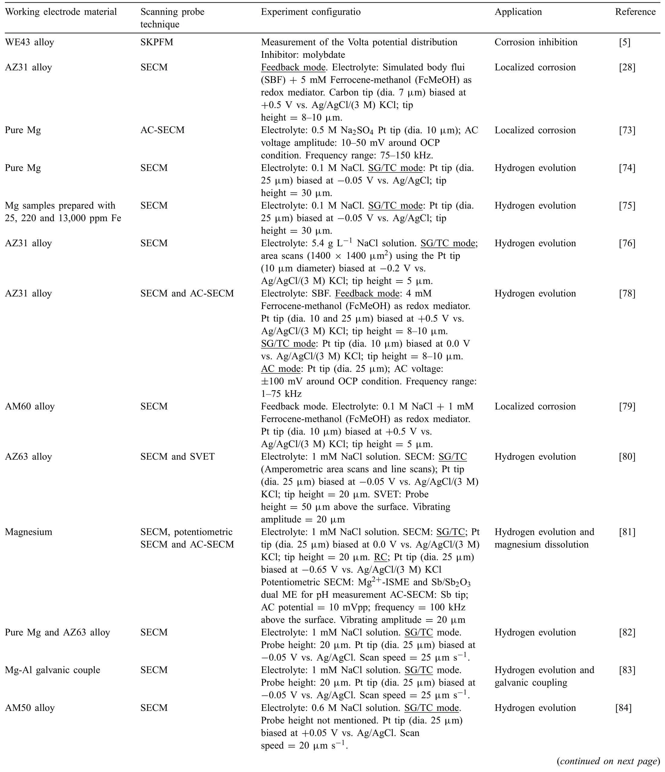
Table 1 Electrode material,scanning probe technique and configuration application and reference for studies on the corrosion processes occurring at the surfaces of uncoated magnesium-based materials.
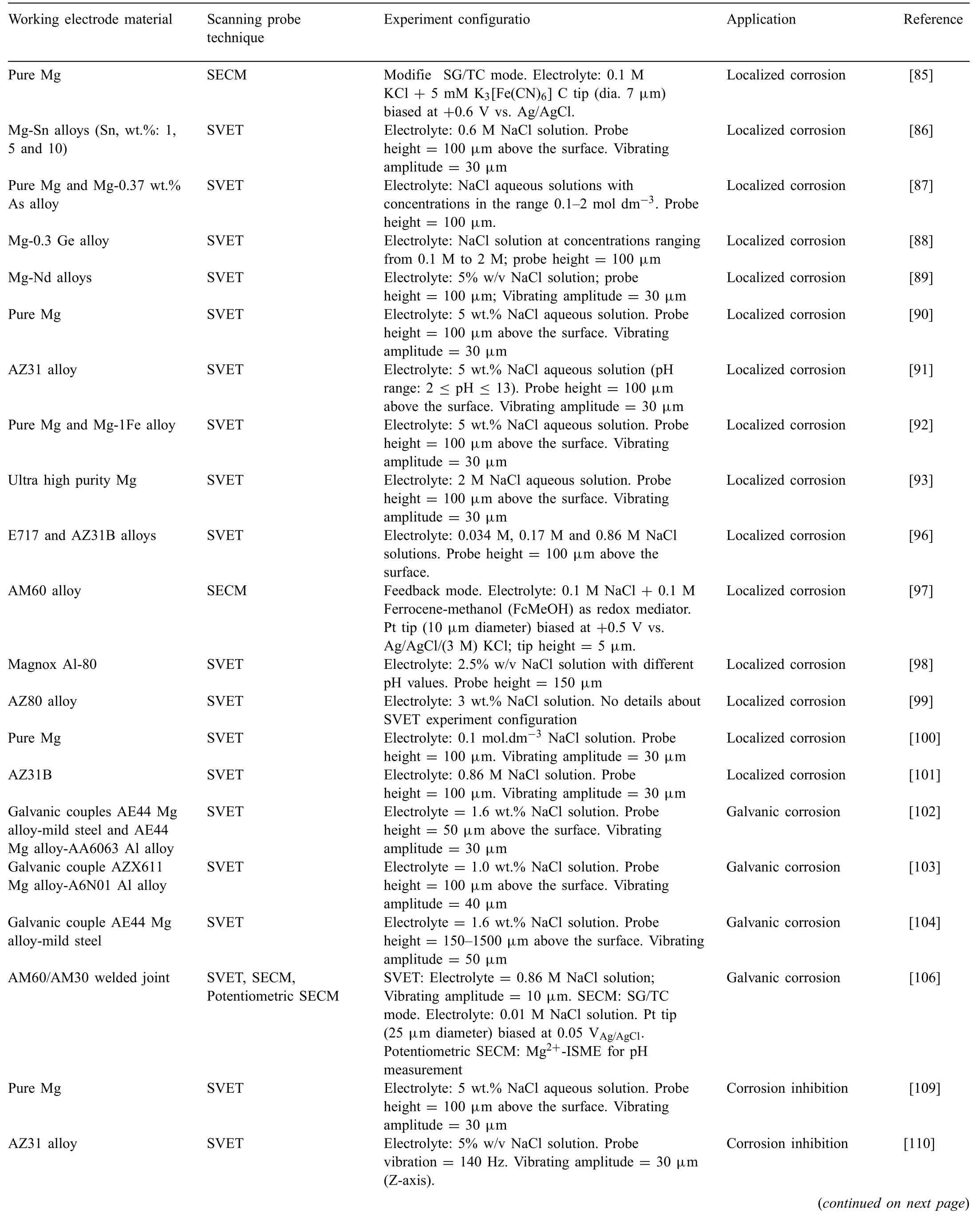
Table 1 (continued)

Table 1(continued)
4.1.1.SECM
Owing to its high spatial resolution and chemical sensitivity,SECM has provided deep insights into the localized corrosion processes of metallic materials.In the fiel of magnesium corrosion,several examples can be found in the current literature.For example,the local corrosion spots and pit nucleation mechanism of the AZ31 alloy were studied by Morcillo et al.[28] using SECM in the feedback mode.The alloy was tested in simulated body fluid SECM allowed determination of local electrochemical activity that correlated with the presence of Al-Mn intermetallics in the microstructure of the alloy,acting as local cathodes that triggered the anodic dissolution of the surrounding Mg matrix.
By using SECM in AC mode (AC-SECM),Baril et al.[73] observed that a thin and insulating MgO layer partially covers the surface of magnesium in a corroding electrolyte,and metal dissolution only occurs at the oxide-free areas although covered by a thick porous layer of Mg(OH)2.Enhanced hydrogen evolution was observed on the Mg(OH)2covered surface of magnesium using SECM in the SG/TC mode [74].Furthermore,the rate of the hydrogen evolution reaction increased by several orders of magnitude upon anodic polarization,although thickening of the dark layer was only 2–3 times.In a subsequent study,it was observed that the rate of hydrogen evolution was higher with the increase of Fe content in the magnesium sample [75].
Jamali et al.[76] have shown that SECM is able to measure local currents generated by hydrogen evolution on the AZ31B alloy in simulated physiological fluid The SECM was operated at the SG/TC mode.The current map obtained at the open circuit potential is displayed in Fig.8a,whereas the corresponding SEM micrograph of the selected area is shown in Fig.8b.The main spots of hydrogen evolution are the small blue/pink colored sites.One example is indicated by the arrow in Fig.8a.These spots corresponded to regions that are preferentially surrounded by Al-rich inclusions,as reported by other authors [77].Additionally,corrosion pits were also formed at random sites on the AZ31B surface due to the heterogeneous nature of the corrosion process,as also observed by Lamaka et al.[62].Some authors reported that quantitative assessment of the corrosion rate of the AZ31B alloy using SECM depends on further calibration of the instrument,although qualitative evaluation of the cathodic/anodic spots could be successfully determined by probing the hydrogen evolution reaction[78].Liu et al.[79]employed SECM in the feedback mode to study the corrosion process of the AM60 alloy in sodium chloride solution,using ferrocene-methanol(FcMeOH) as redox mediator.The aim was to investigate the initiation and growth of pits on the freely corroding surface of the magnesium alloy by monitoring anodic regions related to changes of the redox mediator.The SECM maps in Fig.9 effectively showed the evolution of active sites during immersion in the electrolyte.After 0.5 h of immersion in 0.3 NaCl solution there is a strong anodic peak (denoted by A in Fig.9a).After 1.5 h of immersion (Fig.9b) this peak disappeared due to repassivation of the damaged area in the surface film However,pitting corrosion took place after 3.5 h,as indicated by the high current spots at peaks B and C in Fig.9c.
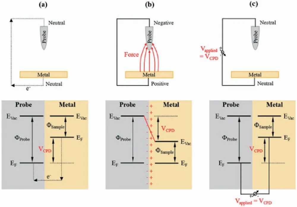
Fig.7.Schematic illustration of the Volta potential difference (VPCD) measured by SKPFM: a) Two different metals are put into electrical contact;b) the Fermi levels of each one of them (EF) reach equilibrium,;c) the Fermi level and the vacuum level (Evac) are lifted to their original positions by applying a voltage equal to VPCD.Reproduced from Ornek et al.[70] (with permission from Taylor and Francis).

Fig.8.(a) SECM map of AZ31B alloy in simulated physiological solution.Substrate at the open circuit potential.Tip biased at 0.0 V vs.Ag/AgCl (3 M KCl);(b) SEM micrograph of the rectangular area selected at (a).Reproduced with permission from Elsevier [76].
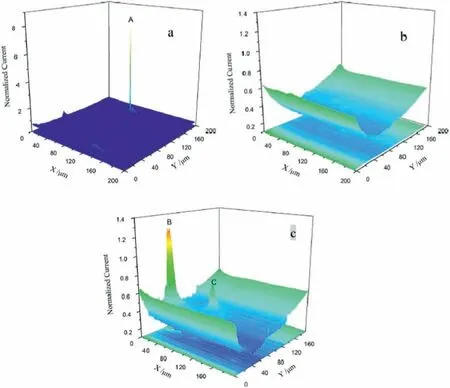
Fig.9.SECM maps of the AM60 alloy in 0.3 NaCl solution with addition of 1.0 mM FcMeOH as redox mediator at different immersion times: a) 0.5 h;b)1.5 h;c) 3.5 h Tip biased at +0.5 V vs.Ag/AgCl (3 M KCl).Reproduced with permission from Elsevier [79].
Filotás et al.[80]developed a novel approach to use SECM to study the anomalous hydrogen evolution during corrosion of magnesium alloys in aqueous electrolytes.The limitation of using amperometric SECM measurements in the SG/GC mode for studying the corrosion process of magnesium substrate under anodic polarization was outlined by the authors.This is due to strong convective effects on the SECM probe caused by excessive hydrogen evolution that ultimately hampers the reproducibility and stability of the measured currents.To circumvent this problem,a three-step (off-on-off)anodic polarization sequence was designed,aiming at reducing the perturbation due to excessive H2evolution on the current signals measured by the SECM tip [81].This approach is depicted in Fig.10.In the initial step,the alloy is left at the open circuit potential for 30 min,freely corroding in the electrolyte.Next,the substrate is anodically polarized,greatly increasing hydrogen evolution,as seen in the inset of Fig.10.After an additional 30 min-period,polarization was stopped and the substrate was let at the open circuit potential for another 30 min-period.This off-on-off operation sequence allowed the authors to obtain comparable current signals under different SECM line scans,thus circumventing the problems of excessive hydrogen evolution that occurs when the substrate is directly polarized.This procedure was extended also to pure Mg and MgAl model galvanic couples,proving its validity to obtain reliable information on the anomalous hydrogen evolution process of magnesium using the SECM[82,83].Tefashe et al.[84] have also shown the applicability of SECM to monitor the local flu of H2due to magnesium corrosion in sodium chloride solution.These authors used the SECM in the SG/TC mode to study the hydrogen evolution process of the AM50 alloy in 0.6 M NaCl solution.They observed that the convective effects due to excessive hydrogen fl w were effectively overcome when specifi experimental conditions were employed (0.6 M NaCl aqueous solution and immersion times up to 60 min).The local hydrogen flu and the size of active areas depend on the time of immersion.SECM gave experimental evidence on the rapid initiation of the corrosion process by monitoring the evolution of the hydrogen flu up to 1 h of immersion.
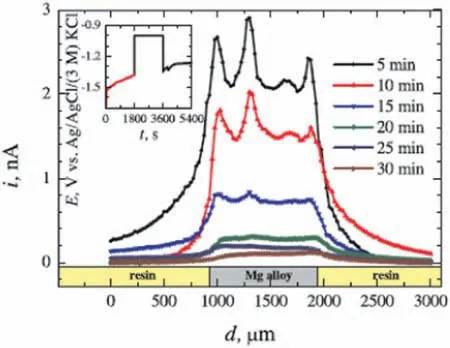
Fig.10.Off-on-off operation of the SECM,as proposed by Filotàs et al.[80]to study the hydrogen evolution process of the AZ63 magnesium alloy in NaCl solution(amperometric line scans recorded at a tip potential of −0.05 V vs.Ag/AgCl (3 M KCl).Reproduced with permission from Elsevier.
Although the SG/TC operation has been successfully employed to monitor the evolution of hydrogen from corroding magnesium materials [76,80,84],its application to detect the chemical species formed at the anodic sites from magnesium activation is prevented by the very negative potential of magnesium electroreduction [64].A modifie SG/TC operation was recently developed by Zhang et al.[85] with the goal to investigate the possible formation of unstable intermediates during magnesium dissolution,namely the hypothetical Mg+ion.In this method,a carbon ME was employed to monitor the formation at the anodic sites of intermediates that can be further oxidized by transferring electrons to a suitable redox species added to the electrolyte.In their work,K3[Fe(CN)]6was added to the electrolyte as redox mediator for such redox conversion process associated to the SG/TC operation mode.
4.1.2.SVET
Complementary information to the SECM can be achieved by probing magnesium surface with a scanning vibrating electrode.SVET is employed to gain insightful knowledge on the location and distribution of anodic and cathodic sites on the corroding surface of magnesium alloys in a more quantitative way than that obtained by SECM,although chemical specificit is not possible.Further limitations mentioned in the literature are related to the lack of sensitivity due to the distance between the probe and the metallic surface,and evaporation of electrolyte during long-term measurements [30].However,the reliability of SVET results for corrosion research in magnesium alloys has been demonstrated by several authors,as described below.
The cathodic activity of freely corroding Mg-Sn alloys in NaCl solution was investigated by Cain et al.[86].They used SVET to assess the distribution of anodic and cathodic areas on the surface of the Mg-Sn alloys.By increasing the Sn content in the alloy,the cathodic activity was suppressed and the anodic current density decreased due to the formation of a more stable passive film mainly consisting of SnO2.SVET was also employed by Williams et al.[87] to investigate the corrosion processes of Mg-As alloys under both freely corroding and anodic polarization conditions.The main interest in this type of alloy resides in its action as a cathodic poison when alloyed to magnesium,limiting hydrogen evolution on iron-rich impurities that triggers local corrosion processes.For example,for open circuit conditions,SVET showed that As addition inhibits breakdown of naturally formed oxide film leading to the formation of a dark film cathodically activated,as shown in Fig.11.No current peaks are seen up to 24 h of immersion (Fig.11a and 11b).The dark fil formed over the surface can be observed in Fig.11c.Germanium,a more environmentally friendly alloying element,played a similar role to that of arsenium,when a Mg-0.3 wt.% Ge alloy was investigated using SVET under both freely corroding and anodic polarization conditions in NaCl aqueous solutions [88].Germanium inhibited cathodic activation due to its incorporation into the MgO/Mg(OH)2layer formed during anodic dissolution of magnesium.
Williams et al.[89] investigated the role of Nd in the localized corrosion mechanism of binary Mg-Nd alloys.Using SVET measurements under freely corroding conditions in a 5 wt.% NaCl solution,they found that intense local anodes formed upon addition of Nd,leading to breakdown of the surface oxide film These local anodes expanded radially over time,while the interior was cathodically activated.Cathodic activation was associated with Nd-rich intermetallic grains formed upon dissolution of the Mg-αmatrix in local anodic regions.
SVET observations by Williams and coworkers seemed to confir the same observation of faster hydrogen evolution rates accompanying the formation of the dark layer of corrosion products on Mg[90].In this case,a filifor pattern of the corrosion product deposition progression coupled with the occurrence of anodically active areas at the front of the filifor trail was observed[90],with the net anodic and cathodic ionic current densities increasing quite in parallel.Similar trends were observed for Mg alloy AZ31 [91].Interestingly,when high chloride concentrations were employed in the experiments,the iron containing magnesium alloy displayed diskshape corrosion spots as it was expected for alloys,but the filifor track appeared on the magnesium surface when decreasing the concentration of the electrolyte [92].Further investigations on the effect of iron dissolution and repassivation were performed using SVET [93–95].
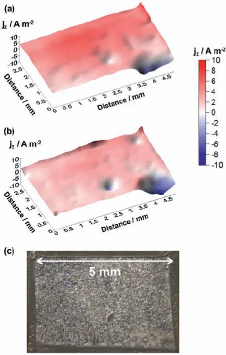
Fig.11.Current maps for the Mg-As (0.37%) alloy in 0.1 dm-3 NaCl solution: a) 4 h;b) 24 h;c) surface aspect after 24 h of immersion.Reproduced with permission from Elsevier [87].
SVET was employed by Kousis et al.[96] to elucidate the filifor corrosion mechanism of the E717 magnesium alloy(Zn and Zr are the main alloying elements with small additions of Nd).Current maps revealed that the leading edge of the filament formed during filifor corrosion presented a strong anodic character,moving over the surface of the alloy.Behind the filaments a cathodically-activated dark surface was observed.By increasing the concentration of chloride ions,the current density increased at both the local anodic regions and the cathodic areas.Ramli et al.[97] have encountered similar results for the filifor corrosion of the AZ31 alloy in 3.5 wt.% NaCl solution.They showed that the filamen front was anodic with respect to its back where corrosion products accumulate,giving it a cathodic character,as displayed in the current maps of Fig.12a,and the corresponding optical images in Fig.12b.
The localized corrosion processes of the Magnox Al-80 alloy (a high magnesium alloy with approximately 0.8 wt.%Al employed as nuclear fuel cladding) were studied by Clark et al.using SVET [98].The effects of pH and chloride concentration on the localized corrosion behavior of the alloy were assessed.SVET showed rapid spreadn of local anodic sites at high chloride concentration (2.5% w/v),whereas at low chloride concentration and high pH the alloy was less susceptible to passivity breakdown.
The microgalvanic corrosion process of the AZ80 alloy was studied by Yan et al.[99].The material was subject to severe plastic deformation (SPD) by successive steps of multidirectional compression,obtaining ultrafin grained twins.Using SVET these authors reported that grain refinemen up to nanometer range suppressed the severe localized corrosion phenomena of the magnesium alloy when compared to the same alloy that did not undergo SPD.The main microstructural difference between the ultrafin grained-material and the conventional alloy was the size and distribution of Mg17Al12precipitates (β-phase).While it was coarse (tens of micrometers) and heterogeneously distributed within the magnesium matrix in the conventional alloy,β-phase precipitates were fin (200 nm) and homogeneously distributed in the SPDprocessed alloy.Hence,microgalvanic effects were greatly suppressed for the ultrafin grained material.SVET effectively detected the different localized corrosion spots for each alloy.The effect of grain size on the corrosion of pure magnesium was investigated by Ralston et al.[100].The samples were grain refine by severe plastic deformation using Equal Channel Angular Pressing (ECAP).SVET was performed under freely corroding conditions in 0.1 mol dm−3NaCl solution at different pH values.SVET revealed that the fine-graine material was more resistant to breakdown of the passive fil than the untreated surface.SVET can also be used to assess the effect of grain size in welded joints by measuring the local corrosion activity across different joint regions,as shown by Kish et al.[101].
As one of the most serious limitations on the widespread use of magnesium alloys in the automotive industry,galvanic corrosion studies have attracted great attention in the scientifi community in the past decade.Deshpande [102] attempted to increase the knowledge on macrogalvanic couples between magnesium and two other structural materials employed in the automotive industry,aluminum and steel.They used SVET to evaluate the corrosion rates of AE44 Mg alloy-mild steel and AE44 Mg alloy-AA6063 Al alloy when in physical and electrical contact.The results showed that SVET yielded compatible results with immersion tests with a difference of around 20% between the current densities measured by each technique.The corrosion rate of the AE44 Mg alloy-AA6063 Al alloy was fi e times slower than that of the AE44 Mg alloy-mild steel couple.Nakatsugawa and Chino [103] employed SVET to study the effect of the area ratio (cathode area/anode area) on the corrosion currents of a galvanic couple consisting of AZX611 Mg alloy-A6N01 Al alloy.Results obtained by SVET showed that anodic current spots increased with the area ratio.It must be taken in account that the occurrence of edge effects between galvanic couples was observed in the case of joining magnesium to a dissimilar metal [104].
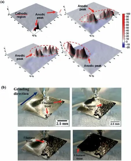
Fig.12.(a) SVET maps of the AZ31 alloy up to 4 h of immersion in 3.5 wt.% NaCl solution;(b) corresponding optical images showing in-situ corrosion during immersion.Reproduced with permission from Elsevier [97].
Galvanic effects also play an essential role in localized corrosion processes that occur in welded joints [105].For example,Salleh et al.[106] used SECM and SVET to investigate the local corrosion processes of friction stir welded AM60/AM30 alloys (Mg-Al-Mn).SECM operation was performed in SG/TC mode in 0.01 M NaCl solution.The immersion time was up to 2 h Scans were taken across the welded joint.A potentiometric SECM measurement was performed to determine the local concentration of Mg2+over the joint.SVET measurements were taken upon immersion of the welded joints in 0.86 M NaCl solution for periods of up to 15 h Three different regions are commonly observed in friction stir welded materials,namely the stir zone (SZ),the thermomechanically affected zone (TMAZ),and the heat affected zone (HAZ).Each one of these zones has different microstructural features (grain size,dislocation density,precipitates) which ultimately lead to distinct corrosion susceptibilities [107,108].The SECM results revealed that the AM60 and SZ regions displayed an anodic behavior in the welded joint within the firs minutes of immersion.However,after 2 h they became cathodic with respect to the AM30 alloy.SVET maps indicated that filifor corrosion started and propagated into the AM30 alloy,resulting in cathodic activation of the corroding welded joint surface.For longer immersion times,the AM60 region of the welded joint was preferentially attacked,resulting in cathodic activation of the AM30 alloy.
Corrosion inhibition of uncoated magnesium may also be studied using SVET,as reported by Williams et al.[109,110].These authors screened several different corrosion inhibitors for magnesium [109] and for the AZ31B alloy [110] at the open circuit potential in 5 wt.% NaCl solution.SVET maps showed current spikes spreading over the sample surface for the least effective inhibitors (NaF,CeCl3and YCl3),indicating the onset of localized corrosion spots.Conversely,cathodic areas remained more time over the surface when effective inhibitors were added to the sodium chloride solution(Na3PO4and Na2CrO4).SVET has also been used to study corrosion inhibition by sodium dioctyl phosphate (DOP) in electron WE43 alloy [111].
4.1.3.Scanning micropotentiometric methods
Due to their chemical sensitivity,microemperometric methods were firs employed in combination with SVET and later alone to provide broader insights into the local corrosion processes of magnesium alloys,allowing a better understanding of their corrosion mechanisms in specifi electrolytes.By carefully planning the experiments,the aforementioned limitations of the probes,such as the fragile nature of the glass micropipettes,and short lifetime [32],can be adequately circumvented to obtain relevant data on the chemical species involved in the local corrosion processes of magnesium and its alloys.
Filotás et al.[112] have studied the galvanic corrosion of an AZ63 Mg alloy-iron couple using potentiometric SECM.The rods of each metal were in electrical contact but not in physical contact.Potentiometric SECM measurements were carried out by means of an innovative multi-barrel microelectrode design,consisting of three different electrodes,a pHsensitive antimony electrode,Mg2+selective electrode and Ag/AgCl reference electrode.This assembly is depicted in Fig.13.The main advantage of such design is to avoid interference from high electric field during SECM analysis that is a typical limitation of single-barrel electrodes.By bringing the reference electrode as close as possible to the ion-selective microelectrode in the multi-barrel design,this limitation can be overcome,as shown by the authors,allowing one to obtain simultaneous accurate measurements of pH distribution and Mg2+activity in the potentiometric SECM operation mode during galvanic corrosion of magnesium alloys.In a subsequent study,the electrochemical activation of both Mg and Ti when galvanically coupled was observed using SECM,and this effect was detrimental to the survival rates of cells used to characterize the biocompatibility of the materials [113].
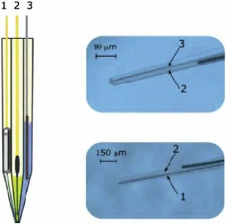
Fig.13.Schematic representation (left) and actual photographs (right) of the multi-barrel electrode assembly developed by Filotás et al.[112]: 1: pHsensitive electrode;2: Mg2+ selective electrode;3: reference electrode.Reproduced with permission from Elsevier.
Gnedenkov et al.[114] showed the applicability of SVET and SIET to reveal local anodic and cathodic spots on the biodegradable Mg-0.8Ca alloy in physiological solution(MEM),whereas pH distributions around Mg-Ca alloys were investigated by Mareci et al.[115] as a function of the calcium content in the alloy,with Mg-0.63Ca degrading faster than Mg-0.89Ca,with a heterogenous distribution of reactivity on the surface of both alloys.Based on SVET/SIET maps,it was possible to infer that the Mg2Ca phase that forms at grain boundaries is anodic with respect to the magnesium matrix [116].SKPFM confirme that this phase displayed more negative electrochemical potential thanα-Mg,acting as an anode in local microgalvanic cells[116,117].Hence,the scanning probe techniques gave support to understanding the main deterioration mechanism of the Mg-0.8Ca alloy in the MEM solution,which occurs by dissolution of the Ca-rich phase,forming a Ca-P phase according to reaction (4):

Microgalvanic effects were also imaged using SIET to account for localized corrosion on E11 and Mg-2Ag alloys in simulated physiological environments [118].
Liu et al.[119]studied the galvanic couple formed between pure Mg and intermetallic compounds (Mg2Ca and MgZn2)using SVET and SIET.Information on the galvanic corrosion behavior of such compounds is a relevant aspect of biodegradable Mg alloys.SVET current maps revealed that Mg2Ca exhibited strong anodic activity while MgZn2was cathodic with respect to pure Mg,as displayed in Fig.14.SIET was able to identify the concentration of Mg2+ions on the galvanic couples,in good agreement with the SVET results.The anodic regions corresponded to the sites where Mg2+concentration was higher (Fig.15).
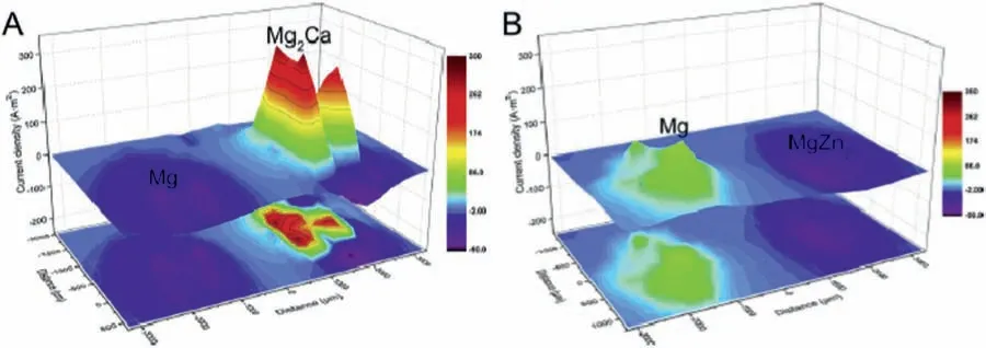
Fig.14.SVET current maps for the a) Mg-Mg2Ca and b) Mg-MgZn2 galvanic couples in Hanks’ solution.Reproduced with permission from Elsevier [119].
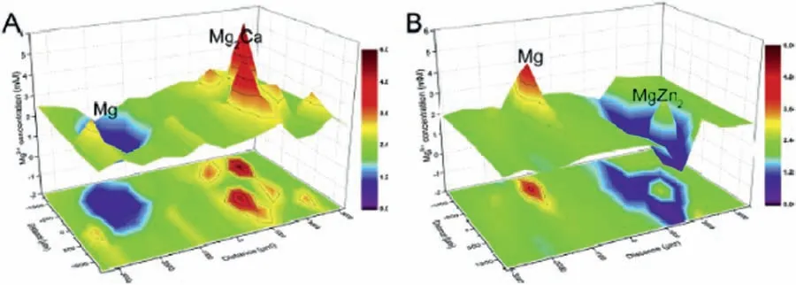
Fig.15.SIET maps for the distribution of Mg2+ ions on a) Mg-Mg2Ca and b) Mg-MgZn2 galvanic couples in Hanks’ solution.Reproduced with permission from Elsevier [119].
4.2.SKP and SKPFM
Since theex situsurface potential distribution on the surface of metallic materials obtained by SKP/SKPFM can be correlated with corrosion potentials,these methods can be considered as a complementary technique to investigate the local corrosion processes of metallic alloys.Its main advantages lie in the relatively simple performance of the experiments without requiring the construction of complex microelectrode probes or limitations concerning the conductivity of the electrolyte,since the measurements are carried out in air[32].However,probe calibration is necessary and concerns about the inherent low resolution of SKP should be taken into account,although SKPFM can overcome this latter limitation.Despite these limitations,SKP has attracted attention of some researchers to study local corrosion processes of magnesium and its alloys,providing valuable information for understanding local surface activity.
SKP was used by Gao et al.[120] to investigate the microgalvanic couples formed on Mg-3Nd-1Li-0.2 Zn alloy due to the presence of nanometric Mg41Nd5precipitates.SKP allowed authors to identify that the Nd-rich precipitates displayed lower Volta potentials (blue spots in Fig.16a) than the Mg matrix (red area in Fig.16a).These sites were associated with the alloy microstructure shown in the SEM micrographs displayed in Fig.16b.Thus,the precipitates were anodic with respect to the matrix,and corroded preferentially.This information was used to clarify the corrosion mechanism of the Mg-3Nd-1Li-0.2Zn alloy in 3.5 wt.% NaCl solution.
Hurley et al.[121] gave an important contribution on the validity of SKPFM as a reliable technique to probe the formation of microgalvanic couples in magnesium alloys.These authors have critically assessed literature and experimental results in order to reveal if the results obtained by SKPFM give the same trend (cathodic or anodic character of specifi crystalline phases) of those obtained by measuring the electrochemical potentials of different magnesium-based materials.For rare-earth rich secondary phases such as Mg12La,Mg12Ce and Mg3Nd they observed that the open circuit potential and the Volta potentials did not correlate well.However,it is useful to provide the overall microgalvanic behavior of Mg alloys,as long as the pH range is kept between 1 and 10 to avoid magnesium passivation and/or dissolution of specifi alloying elements at highly alkaline pH.
4.3.Coated surfaces

Fig.16.(a) Surface Volta potential map and (b) SEM micrograph of the Mg-3Nd-1Li-0.2Zn alloy.Reproduced with permission from Elsevier [120].
Most part of the current literature on the use of scanning probe techniques to study the corrosion processes of magnesium and its alloys is devoted to coated surfaces.In fact,due to the well-spread high electrochemical activity of these materials in aqueous solutions,there is a huge interest in developing protective coatings to control their corrosion rate.In the present section,the literature is reviewed with respect to the applicability of scanning probe techniques to investigate local corrosion processes of coated magnesium-based surfaces.Table 2 lists the references from which the main information discussed in this section was collected,along with relevant experimental details.It is organized in sub-sections devoted to each scanning probe technique.The advantages and limitations of each technique to study the local corrosion processes of coated alloys are the same as those mentioned in Section 4.1 for the uncoated magnesium surfaces and hence,they will not be mentioned here.

Table 2 Electrode material,scanning probe technique and configuration application and reference for studies on the corrosion processes occurring at the surfaces of coated magnesium-based materials.

Table 2(continued)

Table 2(continued)

Table 2(continued)
4.3.1.SECM
As a high-resolution technique,SECM is also employed to investigate local corrosion processes of coated magnesium surfaces.As shown by Ma et al.[122] for a PEOhydroxyapatite coated AZ31B alloy,the evolution of the electrochemical activity around specifi defect sites can be effectively monitored by SECM in the feedback mode.Oliveira et al.[123,124]used the SECM in the SG/TC operation mode to monitor hydrogen evolution from an anodized AZ31B substrate.The samples were anodized in an electrolyte consisting of a mixture of potassium hydroxide and sodium silicate at three different constant current densities (5,10 and 20 mA cm−2).The morphology of the anodized layer affected the corrosion resistance.SECM allowed to identifying the local corrosion spots on the anodized surfaces and correlate them with the morphology of the oxide layers.As shown in Fig.17,SECM 2D maps indicated high electrochemical activity for the untreated AZ31B alloy (Fig.17a) when compared to the anodized samples.
Conversion layers were also characterized using SECM in different operation modes,as shown by Jamali et al.for the investigation of the corrosion protection of a praseodymium conversion fil applied on Mg alloy AZNd[125].The SG/TC mode was thus employed for the detection of hydrogen gas evolution,whereas AC-SECM served to image defects in the conversion coating by measuring local differences in surface resistivity [125].In a subsequent study,the self-healing characteristics of the praseodymium conversion fil in the presence of soluble Pr3+ions were monitored using the SG/TC operation of SECM [126].
Liu et al.[127] have also investigated the self-healing process of a doped-PEO layer.Coating architecture was based on the formation of a hybrid coating consisting of an inorganic phase obtained by micro-arc oxidation doped with the corrosion inhibitor (imidazole-based molecule),followed by spraying a polyurethane top layer on the doped-PEO film They relied in two different actions for corrosion protection.The firs one was based on the release of the corrosion inhibitor impregnated in the PEO porous oxide film The second one is based on mechanical repairing of the polyurethane fil due to shape-memory effect a thermal stimulus and dynamic disulfid exchange reaction.SECM was used to study the self-healing effect of the different coating systems.The operation mode was SG/TC.The tip was polarized at −0.05 V vs.Ag/AgCl to probe the evolution of H2from corrosion of the magnesium alloy substrate(AZ31B alloy).They evaluated the hybrid PEO-polyurethane fil without corrosion inhibitor(MP−0),the PEO-polyurethane fil doped with the corrosion inhibitor (MP−i) and the polyurethane fil doped with the corrosion inhibitor (P−i) after immersion in 3.5 wt.% NaCl solution for 3 and 12 days.The SECM maps are displayed in Fig.18.There is an evident reduction of the electrochemical activity of the MP−isample after 12 days of immersion with respect to the other ones.SECM effectively indicated the self-healing ability of the doped-PEO-polyurethane hybrid coating.
4.3.2.SVET
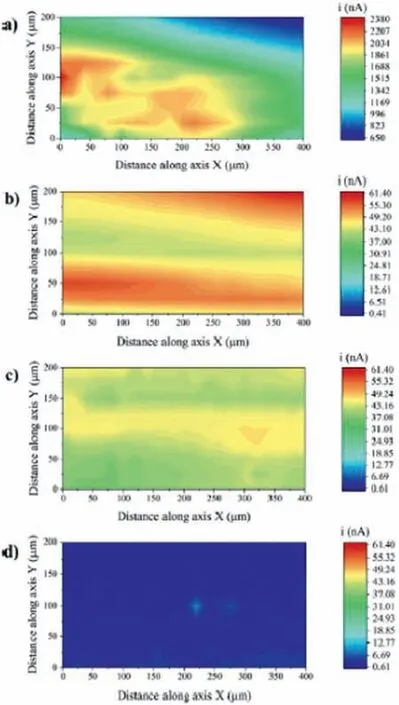
Fig.17.SECM 2D maps of the AZ31B alloy in phosphate buffered solution at room temperature: a) untreated;b) anodized at 5 mA cm−2;b) anodized at 10 mA cm−2;d) anodized at 20 mA cm−2.Reproduced with permission from Elsevier [124].
Due to its prominent role in elucidating the localized corrosion processes taking place at coated surfaces,SVET is frequently employed for the investigation of either simple or complex coating architectures.An example of a simple coating architecture was reported by Liao et al.[128].They prepared a phosphate conversion coating on the AZ91 alloy.An innovative alkaline pretreatment step was proposed to eliminate impurities from the substrate,before formation of the phosphate conversion layer.Specificall ,the pretreatment aimed at dissolving iron-rich impurities such as the Alx(Mn,Fe)yphase that is detrimental to the formation of the conversion layer,decreasing its corrosion protection ability.SVET maps (Fig.19) showed the reduction of electrochemical activity for the pretreated material with respect to coated alloy without pretreatment and the uncoated AZ91 sample.Montemor et al.[129]have also used SVET to study the electrochemical activity of conversion coatings based on cerium and lanthanum compounds on the AZ31 alloy.
Smart coatings for corrosion protection of metallic materials have gained increased scientifi and technological relevance in the past few years.Innovative strategies are available,as recently reviewed by Udoh et al.[130].Self-healing coatings,one class of smart coatings,are those that protect the metallic material from corrosion,and recover their functional properties at a reasonable extent,repairing from a physical damage or restoring their original performance.This effect occurs with no or minimal external intervention [131].Such strategy has been employed in many coating systems for different magnesium alloys.Scanning probe techniques are often employed to investigate the self-healing ability of a particular system.
SVET plays a major role in this scenario,being the most frequently reported scanning probe technique to study the self-healing ability of protective coatings on magnesium alloys.Several instances can be found in the current literature.By introducing an intentional defect in the coating layer,the distribution of anodic and cathodic sites around it may be sensed by the scanning probe.This approach has been adopted by Zhang et al.[26]to study the self-healing ability of a smart coating based on Mg-Al layered double hydroxide (LDH) applied on a cerium-modifie PEO coating on the AZ31 magnesium alloy.The combination of PEO and LDH layers has been recently proposed to improve the corrosion resistance of light alloys,as the LDH layer seals the intrinsic pores of the PEO coating [132].Furthermore,active corrosion protection can be sought by incorporating corrosion inhibitors into the LDH layer due to its intrinsic good ion-exchange ability.Zhang et al.[26] added cerium nitrate to the PEO coating due to the reported ability of Ce in sealing the porous anodic fil and also acting as a corrosion inhibitor for magnesium[133,134].SVET results suggested that the electrochemical activity of the coated alloy decreased with the immersion time in 3.5 wt.% NaCl solution due to precipitation of cerium around the scratched area.Ding et al.[135] used SVET to study the self-healing ability of a tungstate-modifie LDH layer deposited on the AZ31B alloy.The active corrosion protection was imparted by tungstate anions released with time after immersion in sodium chloride solution.Similar finding were reported by Calado et al.[27] on the effect of CeO2as an active corrosion protection additive in an epoxy-silane layer deposited on the AZ31 magnesium alloy.CeO2nanoparticles were incorporated into a mixture of epoxy and silane.This mixture was,then,deposited on the AZ31 substrate by dip coating.The self-healing ability of the CeO2-doped coating was studied using SVET,after promoting an artificia circular defect in the coating layer.SVET maps obtained up to 50 h of immersion in 0.05 M NaCl solution revealed that strong cathodic activity occurred for the blank coating,indicating fast consumption and precipitation of magnesium ions,especially in the firs hours of the experiment.For the CeO2-doped coating the electrochemical activity around the defect was much lower in the firs hour of immersion.After 22 h of immersion the electrochemical was still low in comparison with the blank film as shown in the current distribution maps of Fig.20.
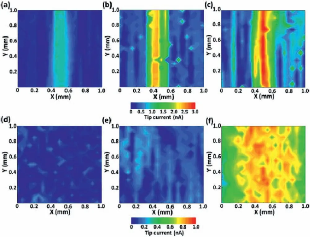
Fig.18.SECM current maps of the samples prepared by Liu et al.[127]: a) MP−I;b) MP−0;c) P −i after 3 days of immersion in 3.5 wt.% NaCl solution;d) MP−I;e) MP−0 and f) P −i after 12 days of immersion in 3.5 wt.% NaCl solution.Reproduced with permission from Elsevier.

Fig.19.SVET current distribution maps of the coated AZ91 alloy after immersion up to 24 h in 3.5 wt.% NaCl solution: a) uncoated alloy;b)conversion coating without pretreatment;c) pretreated and conversion coated sample.Reproduced with permission from Elsevier [128].
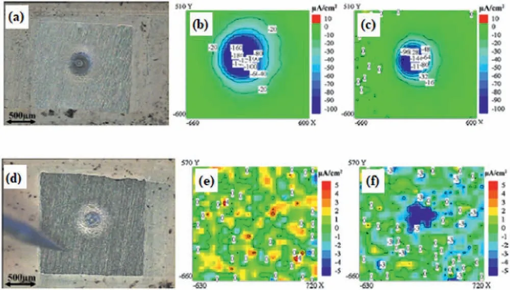
Fig.20.a) optical micrograph and current distribution maps obtained by SVET in 0.05 M NaCl after b) 1 h and c) 20 h of immersion for the blank coating;d) optical micrograph and current distribution maps obtained by SVET in 0.05 M NaCl after e) 1 h and f) 22 h of immersion for the CeO2-containing coating.Reproduced with permission from Elsevier [27].
Similar approaches for SVET analysis were reported by other authors.For instance,Xiong et al.[136]studied the selfhealing ability of a biocompatible silk fibroi coating doped with K3PO4,spin coated on the biodegradable Mg-1Ca alloy.Adsul et al.[137] prepared a sol-gel coating using halloysite nanocontainers fille with cerium and zirconium-based corrosion inhibitors.The substrate was the AZ91D alloy.The selfhealing ability of the hybrid organic-inorganic sol-gel layer was revealed by SVET current maps,as displayed in Fig.19.The high current peak at the coating defect at the initial immersion period in 3.5 wt.% NaCl (Fig.21a) is gradually reduced by the self-healing action of the corrosion inhibitors fille in the coating matrix (Figs.21b-d).
SVET was also useful to reveal the inhibition mechanism of a hybrid PEO-sol gel coating doped with different corrosion inhibitors for the active protection of the AZ91 alloy,as reported by Chen et al.[138].Firstly,a PEO layer was deposited on the substrate.The corrosion inhibitors (sodium salts of either glycolic,4-aminosalicylic or 2,6-pyridinedicarboxylic acids) were impregnated into the PEO fil by immersion.Additionally,a top sol-gel coating was applied to seal the pores of the PEO layer and immobilize the inhibitors.The peak anodic and cathodic current densities were registered with the immersion time in 0.05 NaCl solution.As shown in Fig.22,in the presence of the inhibitors,the electrochemical activity was significantl reduced with time.
The corrosion mechanism was explained based on the schematic representation of Fig.23.Rapid dissolution of the magnesium substrate occurs through the coating defect for the PEO-sol-gel layer without addition of corrosion inhibitors(Fig.23a).Conversely,in the presence of the inhibitors,some functional groups were able to adsorb on the magnesium surface,decreasing the anodic area exposed to the electrolyte,and,ultimately,reducing substrate dissolution.Moreover,stable chelate complexes may form between the inhibitors and impurities (especially harmful iron-rich compounds) in the magnesium alloy.Re-deposition of such impurities on the magnesium surface is detrimental to its corrosion resistance[139].This effect would be,therefore,suppressed by the action of the corrosion inhibitors,further enhancing the corrosion protection ability of the doped coating.Another example of using SVET for studying the active corrosion protection of an inhibitor-doped hybrid PEO layer can be found in a work by Yang et al.[140].They developed a PEO-epoxy coating doped with 3-methysalicylate to inhibit the corrosion process of pure magnesium.SVET current maps confirme a decrease of the electrochemical activity around a defect in the coating layer after immersion in sodium chloride solution for 24 h An alternative system involving a PEO-coating in combination with lithium leaching coating technology was characterized by Wieerzbicka et al.[141].
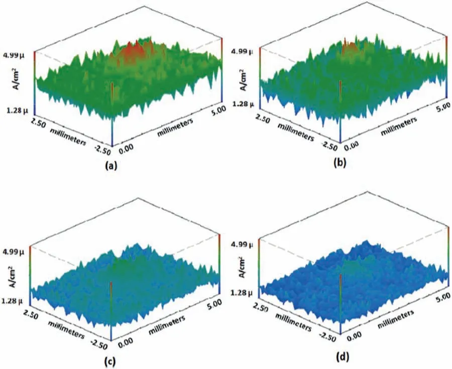
Fig.21.SVET current density maps of the hybrid sol-gel coating developed by Adsul et al.[137].The maps correspond to different immersion times in 3.5 wt.% NaCl solution: a) initial;b) 1 h;c) 12 h;d) 24 h.

Fig.23.Schematic illustration of the corrosion mechanism proposed by Chen et al.[138] for the hybrid PEO-sol-gel coatings doped with different corrosion inhibitors.Reproduced with permission from Elsevier.
The protective character of a single oxide layer produced by PEO on the AZ30 alloy was assessed by Rodrigues et al.[142].The evolution of the electrochemical activity was monitored by SVET up to 24 h of immersion in a physiological solution.The barrier effect of the PEO fil was evident,as indicated by the small ionic current densities observed in the SVET maps compared to the bare substrate.Another interesting system characterized by SVET was the sacrificia protection provided to the alloy matrix (Mg5Gd) by a coating of the same alloy material applied on its surface by magneton sputtering [143].
4.3.3.SIET
SIET is often employed in combination with SVET to assess the integrity of protective coatings.This approach was reported by Gnedenkov et al.[144].They developed a plasma electrolytic oxidation (PEO) layer whose pores were sealed with superdispersed polytetrafluoroet ylene (SPTFE) to improve the barrier properties and control the degradation rate of the magnesium alloy substrate [144,145].The local corrosion activity was monitored by SIET and SVET up to 30 h of immersion in physiological solution.In the absence of SPTFE,current density and pH variations indicated corrosion of the magnesium substrate (MA8 alloy) during immersion due to the porous nature of the unmodifie PEO film
Lamaka et al.[146] assessed the integrity of a hybrid epoxy-silane coating using a combination of SVET and SIET.The substrate was the AZ31 alloy.After immersion for up to 27 h in 0.05 M NaCl solution,localized electrochemical activity vanished when compared to the initial exposure to the corrosive electrolyte,as shown in the current density maps(Fig.24b and 24e) and pH maps (Fig.24c and 24f).This healing effect was not intentionally imparted by adding any corrosion inhibitor,but was ascribed to the possible inhibition action of diethylenetriamine (DETA,epoxy hardener) in conjunction with the formation of insoluble corrosion products during anodic dissolution of the magnesium substrate.These authors preferred using the term “fault-tolerance effect” instead of “healing” to explain this mechanism.
The approach based on doping PEO layers with corrosion inhibitors for providing active protection to magnesium alloys was also conducted by Gnedenkov et al.[147,148].These authors used SVET and SIET to study the evolution of the electrochemical activity and pH changes on defects intentionally made in the surface of the doped-PEO layers deposited on the MA-8 magnesium alloy.As proposed by Galio et al.[149],the corrosion inhibitor compound was 8-HQ.As shown by the SIET mapping (Fig.25) of the pH distribution around a defect in the 8-HQ-doped PEO layer,the pH was still alkaline after up to 7 days of immersion.The areas with lower pH values are local anodes (blue area in the SIET maps),while the areas with more alkaline pHs are the local cathodes (red area in the SIET maps).The decrease of the pH at the local anodes was due to the following reaction (5):

The self-healing ability of the 8-HQ-doped PEO layer was explained [149] by the formation of magnesium hydroxyquinalinate Mg(8-HQ)2,according to Eq.(6).This reaction occurs in the defective zone (anodic areas).SIET confirme this mechanism.The combination of SVET and SIET was also employed by Karavai et al.[150] to investigate the active corrosion protection of a sol-gel doped with 1,2,4,-triazole,F−and Ce3+ions as corrosion inhibitors for the AZ31 magnesium alloy.They highlighted the relevance of SIET to obtain complementary information on the electrochemical activity inside microdefects in the coating layer.

4.3.4.LEIS
The applications of LEIS have mainly focused on investigating the local corrosion processes of coated magnesium alloys because it provides a unique information on the local impedance/admittance of coated systems with high sensitivity,allowing one to obtain quantitative information with regard to the electrochemical processes taking place at specifi sites [32].It is also often employed in combination with other scanning probe techniques,such as SVET,giving a complete picture of the corrosion mechanism involved in the local degradation of coated surfaces.A point of improvement is the relatively low spatial resolution (in the order of a few micrometers) of the LEIS probe,as mentioned by Gharbi et al.[151].
LEIS may also give fundamental understanding on the local electrochemical activity of coatings relying rather on barrier properties than on self-healing effects.An example of a LEIS map for hydroxyapatite-coated AZ31 magnesium alloy in simulated body flui (SBF) is shown in Fig.26 [122].
Fu et al.[152] developed a diffusion coating on the surface of the AZ91D.The fil consisted of multilayer structure formed by Mg17Al12(inner layer) and Mg2Al3(outer layer)by immersion in an aluminum-containing molten salt at 400°C.The continuous intermetallic layer formed on the AZ91D substrate increased the corrosion resistance,as expressed by the LEIS 3D maps that showed impedance modulus up to 10 times higher for the coated alloy (Fig.27b) in comparison with the uncoated substrate (Fig.27a) after immersion in 3.5 wt.% NaCl solution.Similar information was obtained by Zheng et al.[153] for a PEO/sol-gel hybrid coating deposited on the AZ31B alloy.Using LEIS,the impedance was monitored at a defect site up to 6 h of immersion in a physiological solution.When compared to a pure PEO layer,the hybrid PEO/sol-gel coating provided better corrosion protection.LEIS successfully indicated the evolution of the electrochemical activity around the coating defect.
Calado et al.[154] used SVET,LEIS and SIET to study the self-healing ability and inhibition mechanism of cerium tri(bis(2-ethylhexyl)phosphate) (Ce(DEHP)3) as an additive for epoxy-silane coating on the AZ31 magnesium alloy.The combined action of cerium cations and phosphate anions was intended to improve the barrier properties of the epoxy-silane layer,as well as forming insoluble corrosion products that heal coating defects,giving active corrosion protection to the magnesium alloy substrate.Fig.28 displays the variation of admittance obtained by LEIS for the Ce(DEHP)3loaded coating with respect to the reference coating with the immersion time in 0.05 M NaCl solution.The corrosion activity at the coating defect of the Ce(DEHP)3-modifie coating after more than 20 h of immersion was even below that of the initial immersion period,showing the active protection of the cerium-phosphate inhibitor.Similar conclusions were drawn by the same group for the self-healing ability of a Ce(DEHP)3-modifie coating on the WE43 magnesium alloy [155].Galio et al.[149] showed the active corrosion protection of 8-hydroxyquinoline-(8HQ)-doped sol-gel coating on the AZ31 alloy using SVET.The reduction of the electrochemical activity of the 8-HQ-doped sol-gel fil was explained by the formation of an insoluble mixed Mg-8HQ compound that prevented the evolution of the corrosion processes by blocking microdefects in the sol-gel layer.
4.3.5.SKP
SKP and SKPFM have also been used to gain insights on the corrosion trend of coated magnesium surfaces [124,156].As recently reported by Xu et al.[157],potential fluctua tions registered using SKP maps could be associated with the homogeneity of the corrosion process on the surface of a TiN/TiO2-coated AZ31 alloy.Furthermore,the magnitude of the potential provides information on the corrosion trend(high potentials are associated with low corrosion susceptibility).According to the SKP maps displayed in Fig.29,it is clear that the uncoated alloy (BS) displays lower potential than all coated samples (T00 up to T60),indicating the lower corrosion susceptibility of the mixed TiN/TiO2obtained by the combination of atomic layer deposition (to produce a TiN layer),followed by surface oxidation.
Williams and Grace [158] reported essential contributions to the understanding of the filifor corrosion mechanism of magnesium using SKP.This technique mapped in situ the local free corrosion potentials of commercially pure magnesium coated with a model organic polyvinyl butyral (PVB)fil with a 10 mm-long artificia line defect.Corrosion was promoted by exposing the coated magnesium substrate to an aqueous HCl solution (1 mol dm−3).Next,after natural drying,the sample was subject to SKP analysis up to 56 h The minimum values of the corrosion potentials were associated with the underfil attack during filifor corrosion,as shown in Fig.30.In this figure the region of the line defect on the PVB fil is located 1 mm at left of the SKP potential maps.It is seen that by increasing the time after corrosion initiation in the aqueous HCl solution,the regions of low potential propagate under the PVB fil to the right of the potential map,coinciding with the advance of the head of the filifor attack(see Fig.31).These results allowed the authors to elucidate the filifor corrosion mechanism of magnesium coated surfaces.The rate of filifor attack was not dependent on the oxygen concentration,so it was not triggered by differential aeration.Conversely,anodic dissolution of magnesium (in the head of the filifor attack region) coupled with hydrogen evolution (cathodically activated in the tail of the filifor attack region) was responsible for the advancement of the filifor attack.Using a similar approach,Kousis et al.[159] have recently employed SKP to study the fili form corrosion mechanism of PVB-coated commercial magnesium alloys (AZ31,AZ91 and E717).As reported for the commercially pure magnesium sample [158],the filifor corrosion mechanism was also based on the anodic dissolution of the substrate at the head of the filamen coupled to the cathodically activated hydrogen evolution at its tail.However,the rate of filifor attack was lower with respect to pure magnesium.
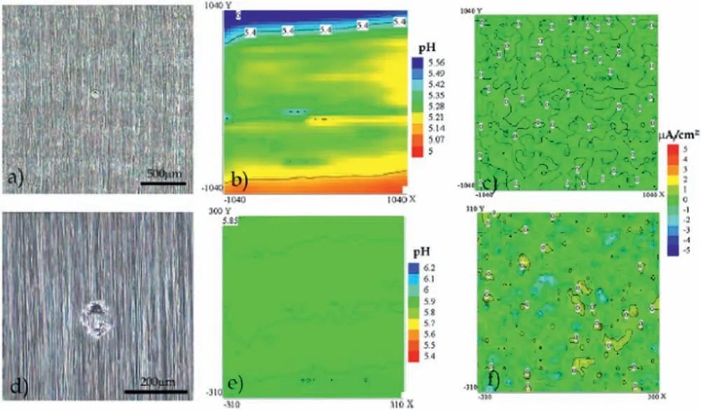
Fig.24.Optical micrographs of the epoxy-silane coated AZ31 alloy after 1 h (a) and 27 h (d) of immersion in 0.05 M NaCl solution and corresponding current density maps (b and e) and pH distribution maps (c and f) obtained by SVET and SIET.Reproduced with permission from Elsevier [146].
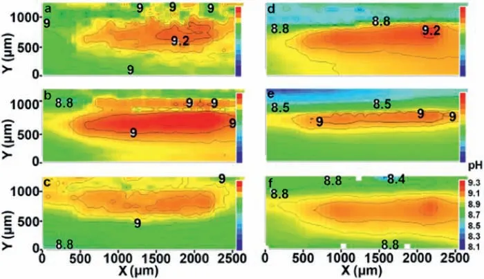
Fig.25.SIET maps showing the pH distribution around the defect of a 8-HQ-doped PEO layer deposited on the MA-8 Mg alloy after different immersion times in 0.05 M NaCl solution.Reproduced with permission from Elsevier [148].
In addition to the above-mentioned filifor corrosion studies of magnesium and its alloys,further information on the use of SKP to investigate organic coating failure mechanisms of these materials was also reported by Williams et al.[160].In this case,they studied the role of cations on the underfil corrosion of a PVB-coated E717 alloy.An artificia defect was produced on the organic fil layer.Next,different aqueous solutions were used to initiate the underfil corrosion process over the damaged area: HCl,NaCl,LiCl,KCl,CsCl or MgCl2.The variation of the local free corrosion potentials in air after exposure to the corrosive solutions was recorded by SKP potential maps taken after different times.Although fili form corrosion was observed for all aqueous solutions,when the alloy was exposed to solutions consisting of cations from group I (LiCl,KCl,NaCl and CsCl),a different mechanism was responsible for the initial coating failure.In this case,filifor corrosion was preceded by a cathodic disbondment mechanism.The relatively high solubility of Group I hydroxides in water was associated with the delamination driven by cathodic disbondment rather than to filifor attack.
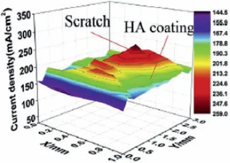
Fig.26.LEIS map of a hydroxyapatite-coated AZ31 magnesium alloy immersed in SBF solution.Reprinted with permission from Elsevier [122].
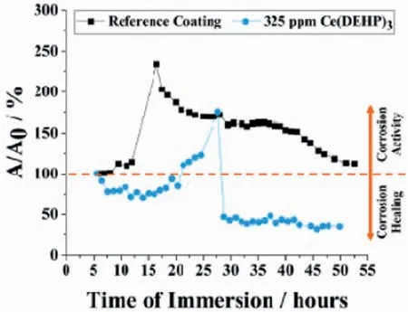
Fig.28.LEIS results showing the variation of the admittance (A) of the Ce(DEHP)3 loaded coating with respect to the reference coating after immersion in 0.05 M NaCl solution.Reproduced with permission from Elsevier[154].
5.Possibilities,limitations and new insights
Magnesium surfaces are susceptible to localized corrosion,although it is sometimes described as general corrosion.However,corrosion processes generalized or localized from a macroscopic standpoint are initiated within the range of nanometers and micrometers.Therefore,a comprehensive understanding of the general aspects of corrosion requires acquisition of data on those scales.In this field there is need for techniques with enhanced spatial resolution which allow obtaining in situ data and lead to a better understanding of the mechanisms of localized corrosion.Consequently,microelectrochemical techniques are becoming essential tools in the study of local corrosion processes.Thus,the localized corrosion in magnesium materials can be characterized by the use of microelectrochemical techniques.

Fig.27.LEIS impedance maps for the AZ91D alloy immersed in 3.5 wt.% NaCl solution:a) uncoated;b) coated with an intermetallic layer consisting of Mg17Al12 and Mg2Al3.Reprinted with permission from MDPI [152].

Fig.29.SKP maps of the AZ31 alloy uncoated (BS) and coated with a hybrid TiN/TiO2 fil (T00 up to T60 where the two digits are referred to the oxidation time employed to produce the TiO2 layer on the TiN surface).Reproduced with permission from Elsevier [157].
Among the scanning probe electrochemical techniques,the Scanning electrochemical microscopy (SECM) has been largely explored in the investigation of corroding magnesium surfaces [64,162].SECM methods commonly used to study the corrosion of metal surfaces are known as substrate generation - tip collection (SG/TC) mode and redox competition mode,while feedback and AC modes are more occasionally used.In all these cases,SECM operates amperometrically.
The aspects of spontaneous corrosion of magnesium surfaces are relatively well known.However,in this material under anodic bias,the development of unusual hydrogen generation requires considerable attention.In the corrosion process,as the magnesium is polarized towards more positive potentials from its open circuit potential (OCP),the generation of hydrogen at the surface tends to accelerate.This phenomenon is commonly referred to as the negative difference effect (NDE) or abnormal hydrogen evolution.

Fig.30.SKP potential maps of PVB-coated magnesium surface after exposure to an aqueous HCl solution after different timespans: a) 12 h;b) 28 h;c) 40 h;d) 56 h Reproduced with permission from Elsevier [158].
SG-TC has been a prominent mode of studying magnesium alloy surfaces [77,78,81,163,164],where a Pt probe is used to oxidize H2emanating from corrosion of magnesium surfaces in spontaneous or non-spontaneous corrosion.Thus,as magnesium corrodes easily,H2bubbles form extensively over its surface.However,using the SG/TC mode when oxidizing the H2gas supplied by the corroding surface,severe effects can be observed on the measurement probe due to gas generation and,consequently,the stability of the faradaic currents (while the magnesium surface is anodically polarized)are severely affected.
On the other hand,the redox competition mode has a very limited use to study the corrosion process on magnesium surfaces since O2plays a minor role in the corrosion mechanism of magnesium materials.In this case,only a small fraction of the O2dissolved in the electrolyte in the vicinity of the corroding surface will be electrochemically reduced.Therefore,only topographic images of the corroding material at different stages may be recorded.This mode also has a limited applicability due to the evolution of H2at the surface,as the H2oxidation range nearly encompasses the potential range used to monitor the oxygen concentration at the probe.Therefore,the oxygen reduction current tends to be masked by the larger oxidation current of hydrogen.
Adverse effects on the measuring probe due to the evolution of H2on the corroding magnesium surfaces can also be observed when using other scanning probe electrochemical techniques,such as SVET and LEIS,since the presence of H2bubbles on the surface makes it difficul to measure sufficientl close to the surface.
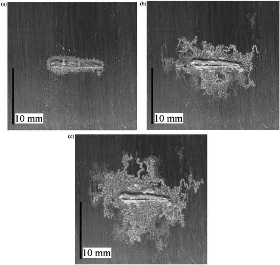
Fig.31.Photographs of a PVB coated magnesium subject to filifor corrosion after exposure to an aqueous HCl solution (1 mol.dm−3).Images obtained after: a) 1 h;b) 24 h;c) 48 h The artificia defect on the PVB coating is seen at the center of the photographs.Reproduced with permission from Elsevier[158].
Ion-selective microelectrodes (ISMEs) have also been used as probes to monitor Mg2+and/or hydrogen ions on corroding magnesium surfaces employing SIET or SECM in potentiometric operation [65,165–168].Although interesting results have been obtained using this method,due to the usual operation with a reference electrode in the bulk of the electrolye,and thus effectively separated from the scanning probe,the validity of a large set of data may be compromised by the electrical fiel established in the electrolyte when a galvanic couple or polarization has been applied to the material under study [169,170].
In this context,a new strategy for the scanning microelectrochemical investigation of H2evolution from magnesium materials in aqueous solution,either at the OCP or anodically polarized,has been reported recently [80].In this study,the evolution of H2generated from the anodic polarization of the magnesium material was detected with high spatial resolution employing the SG/TC mode of SECM by using a 3-step polarization sequence (off-on-off),thus,circumventing the convective influence due to the vigorous generation of H2bubbles formed on the surface during the application of direct anodic polarization.Therefore,this novel experimental procedure can be designed to gain new insights into the behavior of magnesium materials when subjected to anodic polarization,effectively contributing to minimizing the adverse effects due to H2evolution on the surfaces of corroding magnesium alloy which are commonly encountered when scanning probe electrochemical techniques are employed in the study of this type of material.
6.Conclusions
Scanning electrochemical techniques are successfully used to study local corrosion processes of magnesium alloys.The main applications are concentrated on the characterization of microgalvanic effects and pit initiation sites for uncoated alloys.When combined with detailed microstructural examination,these results can support an in-depth understanding of localized corrosion mechanisms.The main limitation is the lack of chemical resolution,especially for SVET,LEIS and SKP,which makes the assessment of the electrochemical activity of composite microstructures a difficul task.In this context,SECM can be used advantageously in this type of characterization.Despite the problems associated with excessive hydrogen evolution during the anodic dissolution of magnesium and its alloys,consistent procedures have been developed to overcome this limitation.On the other hand,it is still necessary to improve the spatial resolution of these techniques to characterize the electrochemical activity of refine microstructures.
Well-established applications for coated substrates mainly focus on studies of the self-healing ability of different types of coating systems (i.e.,organic,oxides,and hybrid layers)doped with corrosion inhibitors.Monitoring the evolution of electrochemical activity in artificia defects in the coating layer is frequently employed to gain knowledge on the mechanism of active corrosion protection of the doped coatings.The conventional barrier properties of undoped coating layers are also assessed by scanning electrochemical techniques.Relevant information can be obtained on the correlation between coating integrity (presence of pores and microdefects)and the ability to protect the underlying meta substrate from corrosion.
Conflic of Interest
None.
杂志排行
Journal of Magnesium and Alloys的其它文章
- Grain refinemen of Mg-alloys by native MgO particles: An overview
- Tailoring MgH2 for hydrogen storage through nanoengineering and catalysis
- In silico studies of magnesium-based implants: A review of the current stage and challenges
- A tightly bonded reduced graphene oxide coating on magnesium alloy with photothermal effect for tumor therapy
- Nucleation of recrystallization in magnesium alloy grains of varied orientation and the impacts on texture evolution
- A novel nanoporous Mg-Li material for efficien hydrogen generation
