Symbol Synchronization of Single-Carrier Signal with Ultra-Low Oversampling Rate Based on Polyphase Filter
2022-11-03ShiliWangRuihaoSongDongfangHu
Shili Wang, Ruihao Song, Dongfang Hu
Abstract: An efficient single-carrier symbol synchronization method is proposed in this paper,which can work under a very low oversampling rate. This method is based on the frequency aliasing squared timing recovery assisted by pilot symbols and time domain filter. With frequency aliasing squared timing recovery with pilots, it is accessible to estimate timing error under oversampling rate less than 2. The time domain filter simultaneously performs matched-filtering and arbitrary interpolation. Because of pilot assisting, timing error estimation can be free from alias and self noise, so our method has good performance. Compared with traditional time-domain methods requiring oversampling rate above 2, this method can be adapted to any rational oversampling rate including less than 2. Moreover, compared with symbol synchronization in frequency domain which can operate under low oversampling rate, our method saves the complicated operation of conversion between time domain and frequency domain. By low oversampling rate and resource saving filter, this method is suitable for ultra-high-speed communication systems under resource-restricted hardware. The paper carries on the simulation and realization under 64QAM system. The simulation result shows that the loss is very low (less than 0.5 dB), and the real-time implementation on field programmable gate array (FPGA) also works fine.
Keywords: symbol synchronization; ultra-low oversampling rate; polyphase filter
1 Introduction
With the development of high data rate communication in recent years, the application of broadband communication has become increasingly widespread, and its bandwidth has grown from several hundred MHz to severalor even tens of GHz. However, compared with the rapidly increasing transmission rate and communication bandwidth, the development of digital devices is much slower. For communication systems which highlight spectrum efficiency (high-order modulation systems), the required high-resolution analog-to-digital converters (ADC) are often difficult to directly sample because of limited sampling rate. Instead, the direct conversion architecture is used instead of intermediate frequency(IF) sampling architecture to reduce the sampling rate. In a direct conversion architecture,the quadrature sampling (with two ADCs that work simultaneously) rate can be close to the bandwidth of the signal, which is a low oversampling system with oversampling rate less than 2.
In communication systems, the symbol timing synchronization mainly estimates and corrects the sampling time deviation, and obtains the best sampling points to recover the signal under the maximum signal-to-noise ratio (SNR)[1]. At present, symbol synchronization methods used in high-speed communication, are mainly classified into two categories: frequency domain(FD) and time domain (TD).
The FD symbol synchronization methods convert the signal to the frequency domain first,obtain the timing deviation by processing the frequency domain components, then correct it by multiplying phase shifting sequences, and finally convert the corrected signal back to the time domain to complete the entire synchronization.The main advantage of the FD method is that it can directly complete the matched filtering and phase rotation in the frequency domain, which saves resources compared to the TD methods [2].Additionally, FD symbol synchronization is easy to achieve under low oversampling rate (less than 2 times of symbol rate). The Godard algorithm [3] and its variants [4, 5] are widely used in recent years. However, a necessary consumption which cannot be ignored is the discrete Fourier transformation (DFT) and inverse discrete Fourier transformation (IDFT) processing.Therefore, FD synchronization requires enormous computing resources for its preliminary transformation. In certain resource-restricted situations, the FD method is difficult to implement.
For TD symbol synchronization, the most widely used method is Gardner’s algorithm [6],which requires at least 2 samples for each symbol. Another TD method is the early-late gate algorithm [7], which requires 3 samples per symbol for comparison. In addition, the square timing recovery [8] combined with the interpolation filter method is more widely used, but the square timing recovery method requires at least 4 samples per symbol. Major studies have shown that when the pulse-shaping factor of the transmission signal becomes lower, the performance of TD symbol synchronization decreases significantly.For a low oversampling system, the roll-off factor of the transmission signal is also low due to the sampling rate. In order to reduce TD symbol synchronization resource consumption, matched filtering and symbol synchronization can be combined [9, 10]. Fiala and Linhart proposed a TD timing synchronization method based on a polyphase interpolation method [11]. This method directly performs TD synchronization through a polyphase interpolation matched filter, which can greatly reduce resource consumption. However,this method requires timing error estimation at an oversampling rate above 2, which is not suitable for applications under low oversampling rates. Furthermore, the synchronization error of this method is limited by the interpolation ratio,and high-precision synchronization requires highmultiple interpolation, which will bring larger resource consumption. Recent researches focus on reducing the jitter of timing error detector [12] or combing symbol synchronization with carrier recovery [13], but not low oversampling rate. The major of the TD methods operates signal at more than 2 samples per symbol [14]. Therefore, traditional TD methods are not suitable for low oversampling systems.
Here we propose a method of timing recovery based on polyphase filter combined with frequency aliasing square timing estimation using pilot symbols, which can adapt to any rational multiple oversampling system (including oversampling rate less than 2). In addition, our method can save resource by combing matched filtering and resampling filtering together.
This paper is organized as follows: Section 1 introduces principle of proposed algorithm; Section 2 designs the system and describes the implementation architecture; in Section 3 we conduct simulations and evaluate the simulation results; Section 4 presents the real-time implementation of our algorithm and its performance;Section 5 is the conclusion.
2 Symbol Synchronization Algorithms
The implementation structure of symbol synchronization can generally accommodate either a feedback architecture or a feedforward architecture, as shown in Fig. 1 and Fig. 2 respectively.The feedback symbol synchronization relies on the loop filter and the numerical control oscillator (NCO). When the loop is stable, the change of its numerical control oscillator is also stable,making it robust against low SNR environments.Because of the loop converging procedure, the timing error is compensated gradually, resulting in less consumption of resources. The feedforward symbol synchronization corrects the current data by compensating the estimated timing deviation directly. This method does not require a loop and has no convergence time, and is quite suitable for burst data synchronization. In both structures, the input signalx(n) needs to be filtered by matched filter first, and the timing recovery filtering (mostly by Farrow interpolation) is performed according to the resultetof the timing error detection module. In addition,the timing error estimation often needs oversampling rate above 2, making the overall working sampling rate of the system relatively high,which is not applicable in the case of low oversampling rate.
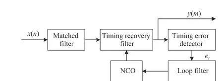
Fig. 1 Feedback symbol synchronization diagram
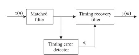
Fig. 2 Feedforward symbol synchronization diagram
Considering the working sampling rate of timing error estimation, it is necessary to reduce its dependence on high-multiple sampling rate.From the perspective of saving resources,matched filter and timing recovery filter can be combined. The symbol synchronization method proposed in this paper mainly consists of two parts: data-assisted square timing recovery based on frequency aliasing and matched polyphase interpolation-decimation filter combined with variable coefficients. The principle diagram of the algorithm is shown in Fig. 3.
In order to reduce the implementation complexity as much as possible, we put the timing error detection module before the matched filter,so that the polyphase filter can directly output the synchronization symbol.x(n) is the input sampling signal, which is sampled independently by the A/D conversion module, and its oversampling rate is assumed to beN/M, whereN>M.The estimated timing erroretis sent to the matched filter coefficient calculation module to obtain the corrected coefficient, which is used for interpolation, filtering and decimation by the polyphase filter ofM/Nmultiplier, and finallyy(m) is the recovered symbol.
The original square timing recovery method is described as follows. In a linear modulation system, the received signal is oversampled byNtimes to obtain a sampling sequence, which can be express as
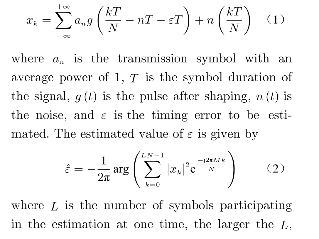

Fig. 3 Proposed symbol synchronization diagram
2.1 Square Timing Recovery Based on Frequency Aliasing
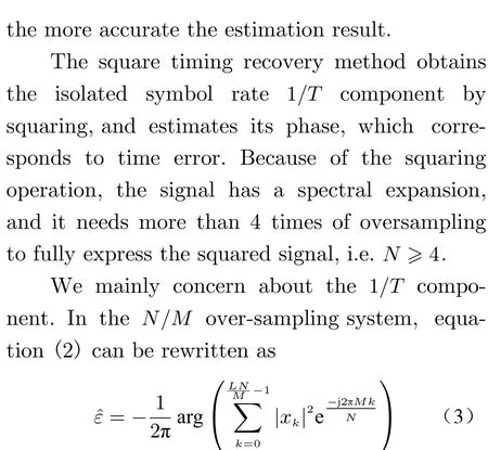
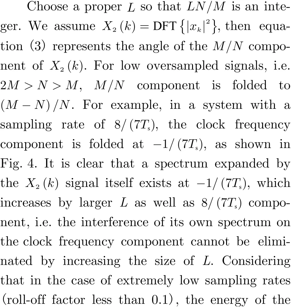
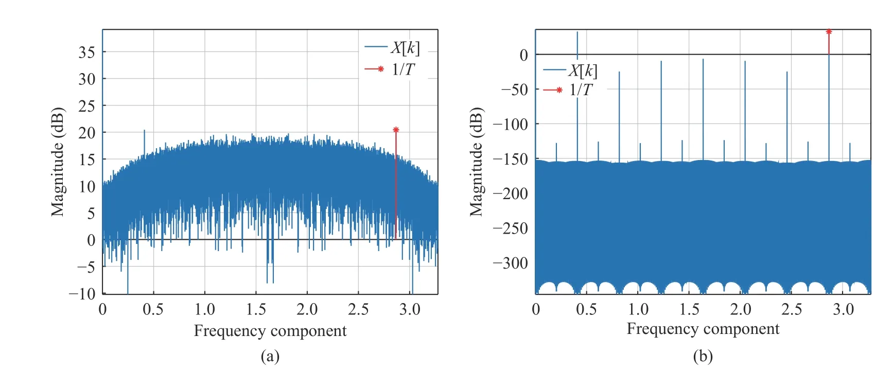
Fig. 5 Comparison of the timing components: (a) the timing component of QPSK signal after aliaing; (b) the timing component of phase alternating signal after aliasing

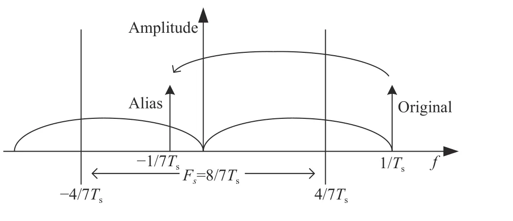
Fig. 4 The timing component aliasing
In order to increase the power of the1/Tscomponent and reduce the self-interference, we use pilot symbols with a strong clock component to estimate timing error. A typical one is the symbol sequence with 180° phase alternating.Because this signal has the strongest clock frequency component, even in the case of Nyquist bandwidth transmission, i.e. the roll-off factor is 0, the clock frequency component is strong enough, which is robust for estimation. Fig. 5 shows the comparison of the clock components of the QPSK signal and the pilot signal (roll-off factor is 0.1, oversampling rate is 8/7, root rising cosine shaping, no matched filter). It can be seen that when the phase alternating signal is used,the peak value of the clock component is obvious,and the self-interference effect is extremely small and can be ignored.
2.2 Matched Filter with Variable Coefficients
At the demodulator, matched filtering is performed on the received signal to achieve the maximum SNR and avoid inter-symbol interference(ISI). Generally, matched filter works at integer multiples of symbol rate. In this paper, it works directly on rational multiples of oversampling rate and combines interpolation with decimation filters.
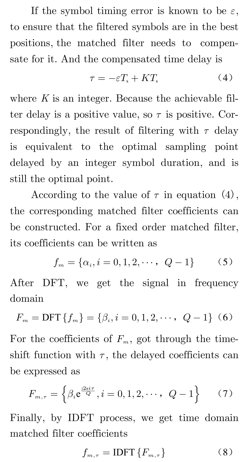
Considering the periodic extension offmduring DFT transformation, it is necessary to perform zero padding operation on the rear offmto ensure that there is no winding distortion. The length of zero padding only needs to be greater than the number of sampling points corresponding to delayτ. Fig. 6 shows the coefficient changes of the matched filter at different delaysτ.
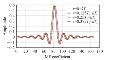
Fig. 6 Coefficients of matched filter under different delay oversampling rate is 7 and filter order is 168
The basic procedure of the variable coefficient matched filter is shown in Fig. 7.x(n) is the input samples, andy(m) is the output synchronized symbol. The input signal with oversampling rate ofN/Mneeds to undergoM-order interpolation andN-order decimation to obtain desired symbols. Commonly, the signal after upsampling needs to be filtered to eliminate the mirror frequency to ensure that there is no aliasing during down-sampling. Here, the variable coefficient matched filter that works atMtimes the symbol rate can complete this function and compensate the timing error simultaneously.
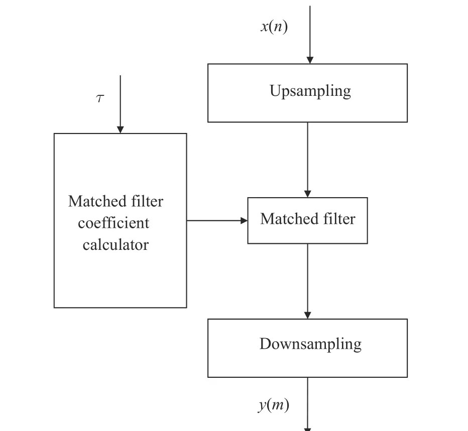
Fig. 7 Procedure of the variable coefficient matched filter
3 System Design and Implementation Structure
Based on the algorithm described above, we design a set of single-carrier signal ultra-low oversampling rate symbol synchronization system.The oversampling rate of the input samples is 8/7 times the symbol rate. The signal pulse is shaped by root raised cosine filter with roll-off factor 0.1. The signal is generated burst transmission mode, and its frame structure is shown in Fig. 8. The±πsequence is the phase alternating sequence in section 2.1. The modulated symbols are 64 QAM.

Fig. 8 Transmission frame
Timing error is estimated by±π sequence using equation (2), and its implementation structure is shown in Fig. 9. The DDS module performs as exponential components of equation (2).Assuming that the timing error accumulated during a frame is relatively small, so the result needs to be updated only once per frame, which makes the complexity reduced greatly by serial computing. In the hardware implementation, we use the CORDIC algorithm to get the angle.

Fig. 9 Implementation structure of timing error estimation
Considering that the matched filter contains the interpolation and decimation functions of rational ratio, the polyphase filter with implementation architecture can greatly save hardware resources.
For aK-order FIR filter, the convolution process can be regarded as a sum of products

wherexi[k] is the filter input signal, andc[k] is the filter coefficient. Whenxi[k] is the up-sampled signal, it only has non-zero values at a few points. The theory of polyphase filtering can be used to shift and extract the filter coefficients.The decimation rate of filter coefficients is the up sampling rateMofx[k]. And after decimation,we can obtain a newMsets of filters, the coefficients of which are

The corresponding implementation architecture of the interpolation part of polyphaser filter is shown in Fig. 10.
After up sampling and filtering, the filtered result needs to be down sampled, and the down sampling rate isN. According to the theory of polyphase filtering, the down sampling operation is placed before the filtering. The filterCmin Fig. 10 can be decomposed intoNgroups of subfilters, the coefficients of which are

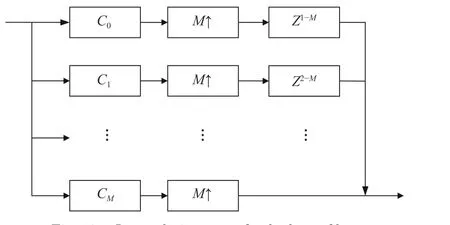
Fig. 10 Interpolation part of polyphaser filter
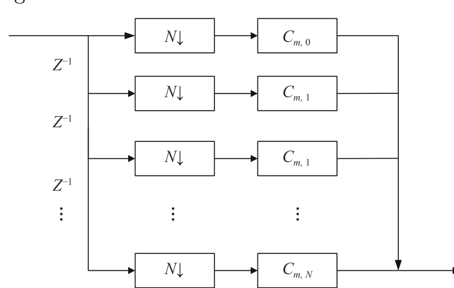
Fig. 11 A part of polyphase decimator based on an arm of filter shown in Fig. 10
According to the above-mentioned principle,the implementation structure of the entire polyphase filter withM/Nrate transformation is shown in Fig. 12.
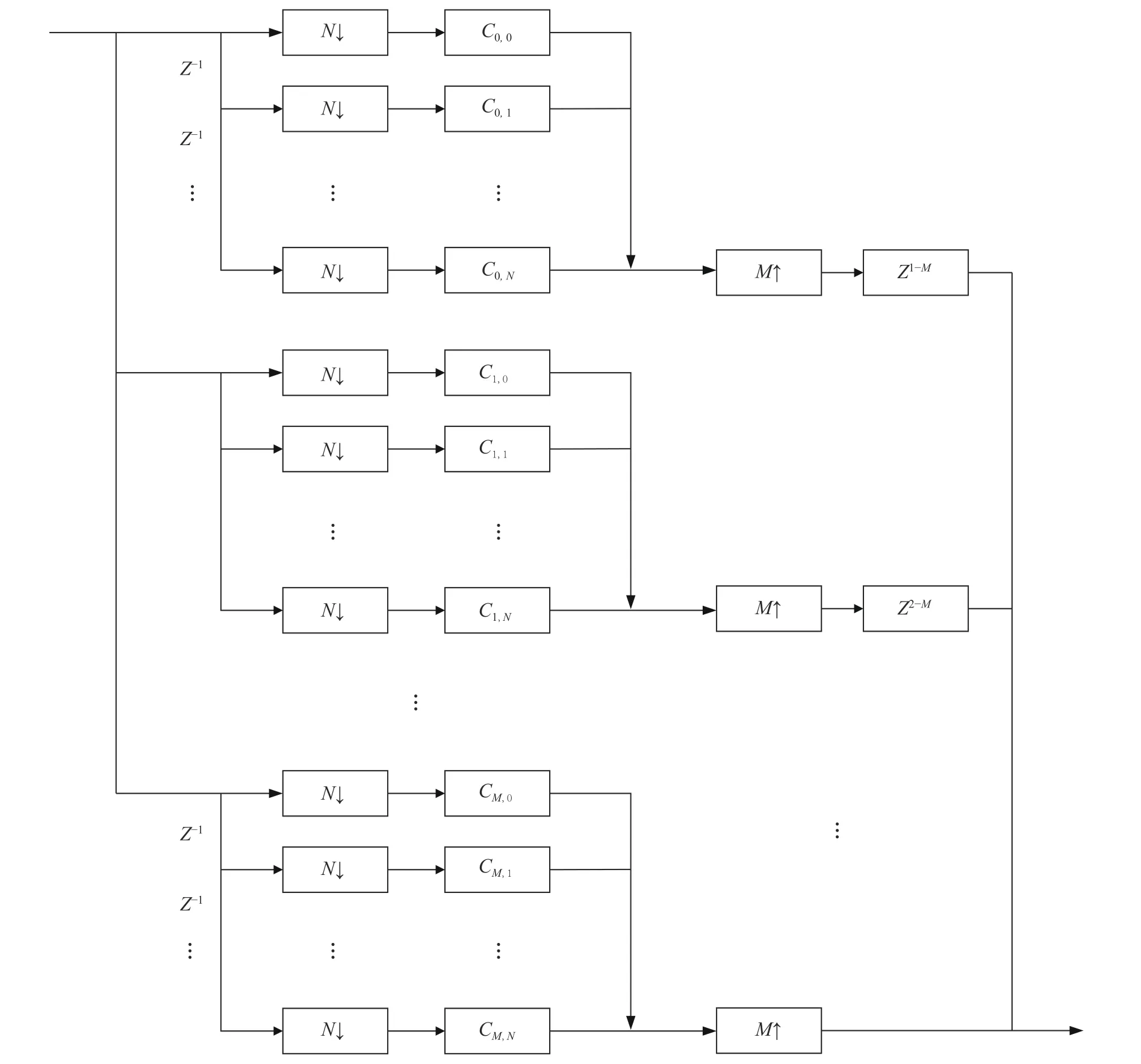
Fig. 12 Entire matched filter
The interpolation coefficient updating needs to use Eqs. (5)–(8) which need to perform FFT and IFFT process, so the calculation resources are relatively large, which is not conducive to real-time demodulation. Here, the compensation coefficients corresponding to different timing errors can be calculated in advance and stored in memory such as the RAM in FPGA, and the timing error calculating can be performed through addressing to reduce computing resources. When the simplifying is adopted, it is necessary to discretize the estimation results.When the discretization density is high, the result is accurate, and vice versa. The specific dispersion is simulated and analyzed in Section 4.
4 Simulation Result and Analysis
4.1 Simulation Results of Timing Error Estimation
The evaluation of timing error performance is mainly based on the estimated mean and variance as measurement indicators. We use the frame structure in Fig. 8 to simulate, the±π sequence length is 56, and the signal processing oversampling rate is 8/7. The signal is estimated by Eq. (3). The SNR of per bit, i.e.Eb/N0, is calculated by 64QAM symbol. And roll-off factor is 0.1.
The average estimated results under different timing errors are shown in Fig. 13 and Fig. 14. Each point in the figure represents the average of 1 000 simulation results. It can be seen that the timing error estimate is consistent with the actual value. When the timing error is ±0.5 symbol periods, the estimation result has a cycle skipping phenomenon due to the influence of noise, and the average value deviation will appear in the average processing. This phenomenon is particularly obvious at low SNR, as shown in Fig. 15. According to Eq. (4), the estimated value takesTsas the period, so the cycle skipping phenomenon will not affect the selection of the best sampling point. It is only a sliding of one symbol period, which has no effect on the synchronization performance.
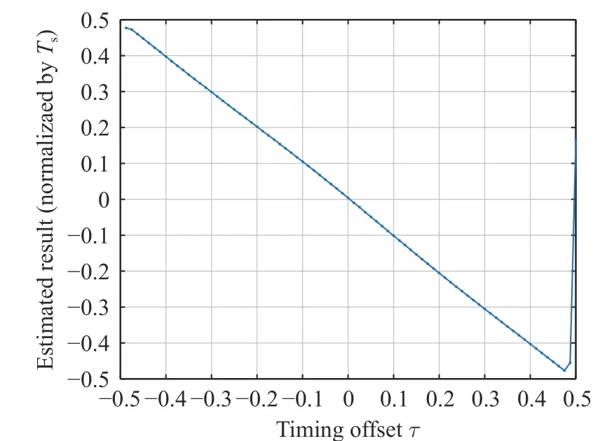
Fig. 13 Timing error estimation result under Eb/N0=9 dB, 1 000 times average
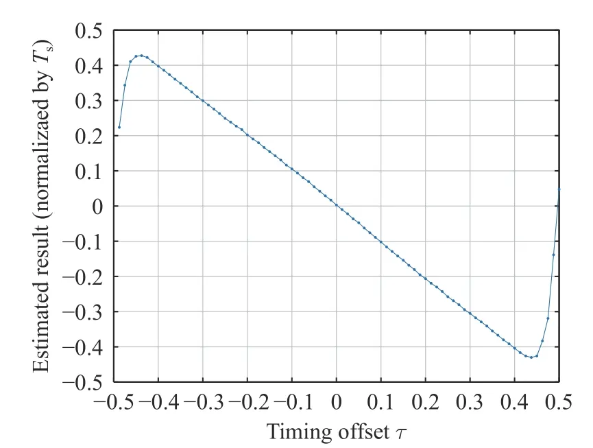
Fig. 14 Timing error estimation result under Eb/N0=–3 dB, 1 000 times average
After determining the unbiasedness of the estimation, we need to consider the jitter of the estimation results under different SNR. We use mean square error (MSE) ofτ(normalized to symbol period) to evaluate estimation performance.
Ref. [8] gives the theoretical variance of timing estimation as
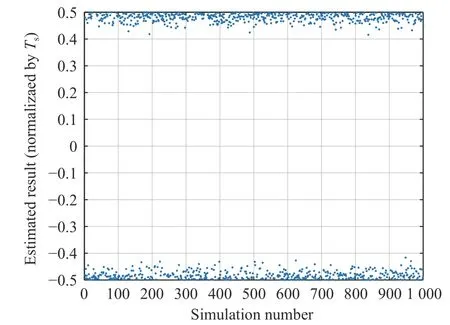
Fig. 15 Timing error estimation result under Eb/N0=–3 dB,actual timing error is 0.5

where three terms are generated by (signal × signal), (signal × noise) and (noise × noise) respectively. Here the±πsequence is used, so the term(signal × signal) can be ignored.
Fig. 16 shows the results of timing error MSE under different SNRs, and the estimated result is close to (signal × noise) limit, which are similar to results of squared timing recovery method, but the roll-off factor is much smaller tha
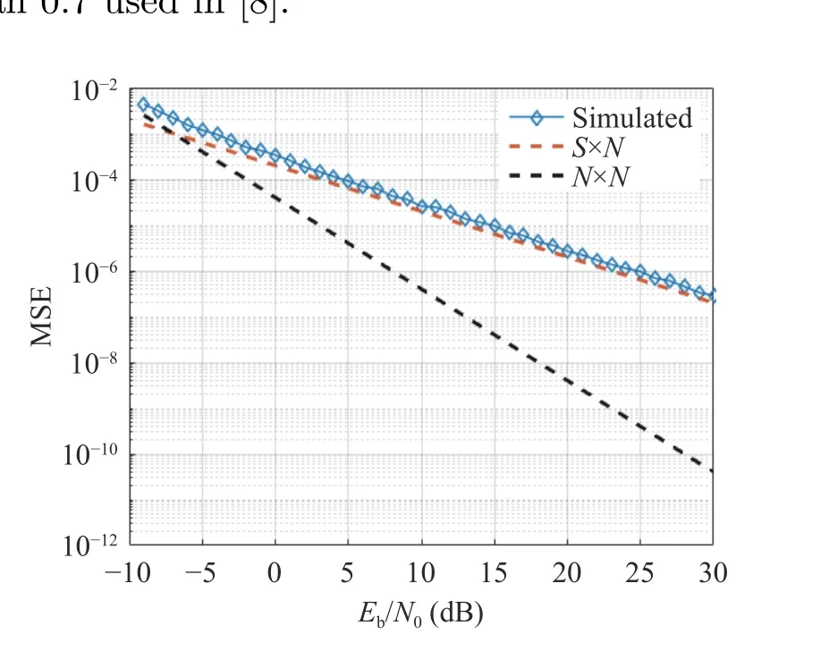
Fig. 16 MSE of timing error estimation under different SNRs
4.2 Simulation Results of Filtering
Before simulating interpolating, we need to determine the precision of the coefficient discretization mentioned at the end of section 3.
Firstly, we consider the demodulation loss of 64QAM when the timing error exists. The bit error rate (BER) under different timing errors are simulated. Fig. 17 shows the BER corresponding to different timing errors whenEb/N0is 100 dB (almost noise-free). The number of simulated symbols for each deviation point is 4×10⁶.We can see that when the BER is 10–6, the corresponding timing error is about 0.035, and the timing error corresponding to BER=10–3is about 0.045. It can be seen that 64QAM is very sensitive to timing error.
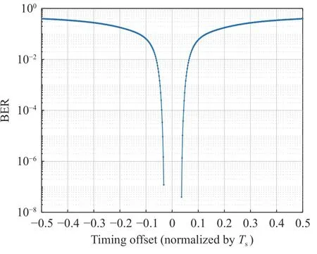
Fig. 17 The BER under timing errors when Eb/N0=100 dB
Now we take account of the SNR. The theoreticalEb/N0threshold of 64QAM is 14.7 dB when the BER is 10–3. At this time, different BERs corresponding timing errors are shown in Fig. 18. It can be seen that the BER deterioration is not obvious within timing error 0.01.
In the case of different SNRs, the BER corresponding to the slight timing error is shown in Fig. 19. Simulation shows that under the same BER=10–3, when the normalized timing error is 0.006, 0.01 and 0.02, the performance loss is 0.25 dB, 0.3 dB and 1 dB, respectively. We tradeoff between implementation complexity and performance, and we accept the loss when the normalized timing error is 0.01.
In addition, the result of each estimation needs to be maintained for one frame time, so the cumulative timing error caused by the sampling clock offset (SCO) also needs to be considered.Suppose the clock offset between both ends of the system isfSCO, and the frame length isLint, the accumulated timing errorτSCOduring one frame is

When the system sampling clock deviation is 0.1×10⁻⁶and the tolerance is set to 0.006,Lintcan be up to 60 000 symbols.
Based on the above conclusion, the normalized timing error discretization can be done at an interval not greater than 0.008, and the corresponding maximum timing quantization error is 0.004. In this way, only about 128 sets of coefficients are needed between –0.5 and +0.5. In implementation, the filter length is set 168 steps(including the zero-padded part), and it is split into 56 sub-filters, each with only 3 coefficients.
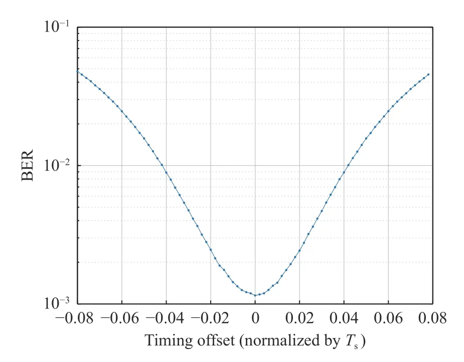
Fig. 18 BERs of different timing errors, 64QAM at Eb/N0=14.7 dB
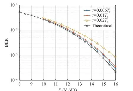
Fig. 19 BER of 64QAM under slight timing errors
Assuming the system has a sampling clock deviation of 0.1×10⁻⁶, the simulation results under different SNRs are shown in Fig. 20 , Fig.21, Fig. 22. To compare the performance of our method with general methods, we simulate the Gardner method based on 4 oversampling rate without sampling clock offset, and with a roll-off factor 0.1. Fig. 23 and Fig. 24 shows the Gardner synchronization results with no noise andEb/N0= 18 dB. We can see that the performance of Gardner method is limited by low rolloff factor especially when SNR is high.
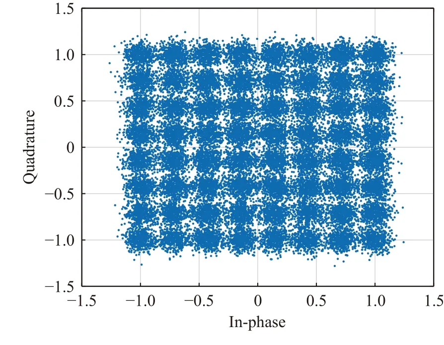
Fig. 20 Constellation of synchronized 64QAM, Eb/N0=12 dB
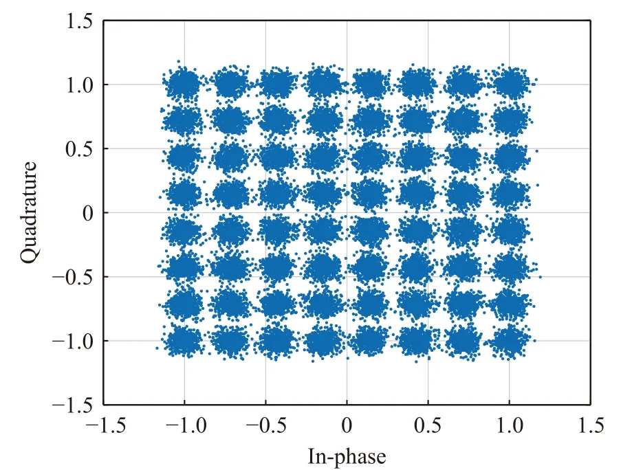
Fig. 21 Constellation of synchronized 64QAM, Eb/N0=15 dB
The final system’s BER curve is shown in Fig. 25, It can be shown that the loss is less than 0.5 dB. Under medium and high SNRs, the jitter of timing error estimation is already extremely small, so the estimation accuracy is high enough.In addition, the extra error caused by coefficient discretization is approximately uniformly distributed, and the maximum deviation does not exist all the time, so the performance is slightly better than the case ofτ0.01 in Fig. 19. Fig. 25 also illustrates Gardner method’s result with large loss due to small roll-off factor.
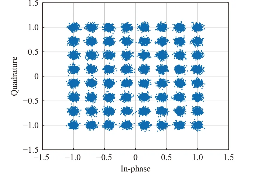
Fig. 22 Constellation of synchronized 64QAM, Eb/N0=18 dB
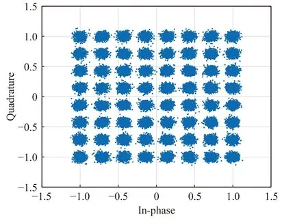
Fig. 23 Constellation of synchronized 64QAM, using Gardner Method with no noise
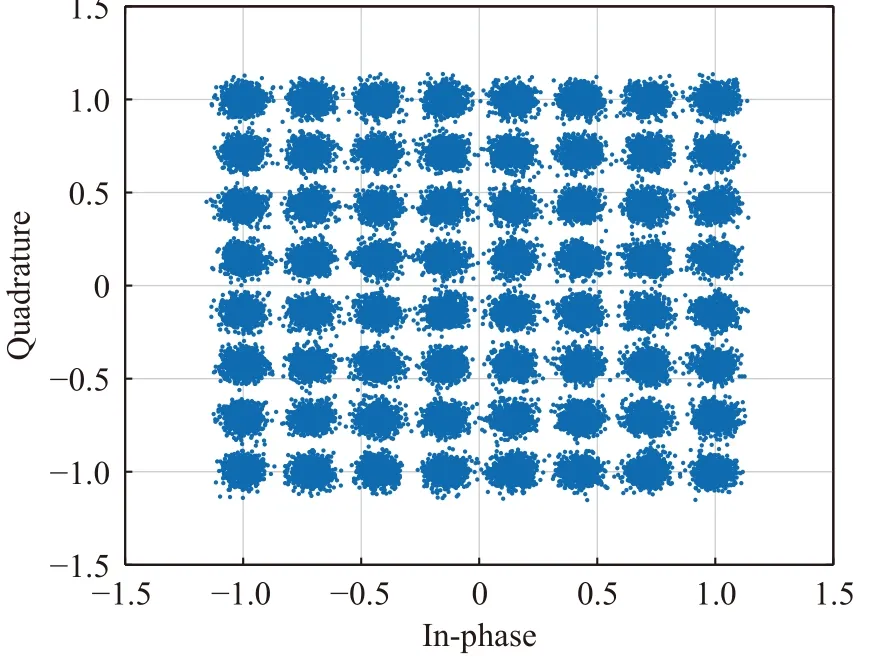
Fig. 24 Constellation of synchronized 64QAM, using Gardner Method with Eb/N0=18 dB
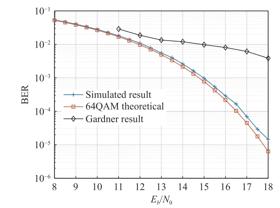
Fig. 25 BER performance of symbol synchronization, 64QAM
5 Real-Time Experiment Result
To estimate the performance of the hardware implementation of our algorithm, we implement it in field programmable gate array (FPGA) of Xilinx XCVU13P series.
The hardware design is realized for an oversampling of 8/7, an operating clock frequency of 150 MHz, 28 symbols per clock cycle (4.2 GBd)and 32 samples per clock cycle (4.8 Gsps). The resolution of ADC is 12 bit. Tab. 1 illustrates the resource usage of XCVU13P series FPGA.

Tab. 1 Resource usage of XCVU13P
The main usage of lookup table (LUT) and DSPs are for the filter processing interpolation of 7 and decimation of 8. In the system, down sampling is inevitable. If the oversampling rate is integer, the resource can be reduced substantially by removing interpolation. For comparison to a frequency-domain architecture, we implemented real-time 256-point FFT and 256-point IFFT module with throughput 4.2 Gsps. Their resource comsumptions are shown in Tab. 2. The FFT and IFFT modules are fundamental for frequency-domain architecture, so the resample from 8/7 to 1 multiple is still necessary and will cost lots of resource.

Tab. 2 Real-time FFT and IFFT resource usage of XCVU13P
Our evaluation system is shown in Fig. 26.We use direct conversion architecture, and 2 digital-to-analog converters (DAC) at transmitter and 2 ADCs at receiver are working simultaneously. One pair of DAC and ADC process inphase signal, and the other pair process the quadrature signal. The baseband I/Q signal is up-converted to IF of 12GHz and the be downconverted back to baseband with I/Q signal. The sample clock offset is limited in less than 10–7by using high stable OCXOs in both sides. The FPGA in the receiver process the received I/Q signal at real-time, and we can capture the demodulated signal from FPGA by JTAG. The signal is modulated as 64QAM with roll-off factor 0.05.
Due to the I/Q imbalance of analog converters and passband fluctuation, the received signal is distorted by non-linearity effects. So equalization is addressed after symbol synchronization.Fig. 27 shows the power spectral density of received signal, and Fig. 28 illustrates the demodulated constellation. It can be shown from Fig.28 that the system works fine.

Fig. 26 Overview of real-time hardware
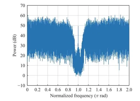
Fig. 27 The power spectral density of received signal
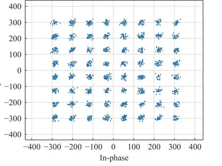
Fig. 28 The final constellation of received signal after demodulation
6 Conclusion
This paper has proposed an ultra-low oversampling rate symbol synchronization method for single carrier signal based on a polyphase filter.This method firstly uses pilot-symbol to estimate the accurate timing error through the frequency aliasing squared timing recovery, and secondly indexes the coefficients of the filter through the timing error, finally completes the accurate symbol delay correction in the filter. The method consumes low resources and can adapt to receivers under any rational oversampling rate,and is particularly suitable for direct conversion communication systems under ultra-high symbol rates (usually the sampling rate is less than twice the symbol rate). The simulation results have shown that the performance loss of this method is small, and it can work stably even when the roll-off coefficient is small. Real-time hardware has been implemented and works fine.
However, the practical application of this method needs to consider the SCO. In some high SCO situations, SCO introduces timing error accumulatively, which limits the maximum estimation interval and increases the frame overhead. Thus we should trade off communication efficiency against performance. Due to its estimation-feedforward architecture, this method is suitable for burst communication system.
杂志排行
Journal of Beijing Institute of Technology的其它文章
- Resource Allocation for Uplink CSI Sensing Report in Multi-User WLAN Sensing
- A Multi-Vehicle Cooperative Localization Method Based on Belief Propagation in Satellite Denied Environment
- Optimization and Design of Cloud-Edge-End Collaboration Computing for Autonomous Robot Control Using 5G and Beyond
- Optimize the Deployment and Integration for Multicast-Oriented Virtual Network Function Tree
- Performance Analysis for Mobility Management of Dual Connectivity in HetNet
- Intelligent Reflecting Surface with Power Splitting Aided Symbiotic Radio Networks
