Intelligent Reflecting Surface with Power Splitting Aided Symbiotic Radio Networks
2022-11-03HuiMaWeiLiLeiSun
Hui Ma, Wei Li, Lei Sun
Abstract: The performance of symbiotic radio (SR) networks can be improved by equipping secondary transmitters (STs) with intelligent reflecting surfaces (IRSs). Since the IRS power consumption is a non-negligible issue for STs, we consider an IRS assisted SR system where the IRS operates under power splitting (PS) mode. We aim at minimizing the IRS power consumption for the ST under the quality of service constraints for both primary and secondary transmissions by optimizing the transmit beamforming, the reflect beamforming and the PS factor. The optimization problem is non-convex. To tackle it, an algorithm is proposed by employing the block coordinate descent, semidefinite relaxation and alternating direction method of multipliers techniques. Simulation results demonstrate the efficiency and effectiveness of the proposed algorithm.
Keywords: intelligent reflecting surface; power splitting; symbiotic radio
1 Introduction
Symbiotic radio (SR) is a promising technology for the internet of things (IoT) where IoT sensors are low-energy devices. In SR, a secondary transmitter (ST) can send messages to an information receiver (IR) by modulating and reflecting ambient radio frequency (RF) signals without employing active components, such as oscillators, up-converters, and power amplifiers. The ST realizes cooperative transmission such that the IR can jointly decode the messages from it and the primary transmitter (PT) that transmits RF signals. Thus, the secondary transmission can not only deliver information but also improve the primary transmission in return by providing additional multipath. In many studies on SR, STs are equipped with single reflecting antenna [1, 2]. However, due to the double fading effect, the secondary links are weak. The performance of secondary transmissions and the enhancement to primary transmissions are limited.
To address the aforementioned issue, intelligent reflecting surface (IRS) technology can be applied. An IRS is a two-dimensional artificial structure consisting of a large number of reflecting elements. These elements can reflect signals and induce phase shifts to the reflected signals[3]. Thus, secondary transmissions can be implemented through IRSs by phase shift keying(PSK). In addition, through appropriate phase shifts at IRS elements, fine-grained reflect beamforming can be achieved. Therefore, equipping STs with IRSs has great potential to improve the SR performance [4]. Nevertheless, IRSs require power for controlling the phase shifts at reflecting elements and the power is a not negligible burden for low-energy STs, since the element number is large [5]. Recently, some research considered enabling IRSs to harvest wireless energy by power splitting (PS), i.e., harvesting energy from a part of the incident signals and reflecting the other part [5–7], which motivates us to study IRS with PS assisted SR networks for relieving the burden of STs caused by IRS power consumption.
In this letter, we consider an IRS assisted SR system where there exists a PT, a ST and an IR. The IRS operates under PS mode. We minimize the IRS power consumption for the ST under quality of service (QoS) constraints for both primary and secondary transmissions by optimizing the IRS reflect beamforming, the transmit beamforming at the multi-antenna PT and the PS factor. The transmission optimization problem is non-convex because of coupled optimization variables. To tackle it, we develop an algorithm by employing the block coordinate descent (BCD), semidefinite relaxation (SDR)and alternating direction method of multipliers(ADMM) techniques. Simulation results demonstrate that the proposed transmission optimization algorithm with much lower complexity can perform similar to its counterpart, which justifies the effectiveness of the proposed algorithm.
2 System Model and Problem Formulation
We consider a SR system as shown in Fig. 1. In the system, there exist a PT withNantennas, a low-energy ST wired with an IRS, and a singleantenna IR. The IRS consists ofIRIRS elements,denoted by a setI={1,2,...,IR}. The PT transmits signals to the IR via beamforming. At the same time, in order to send messages to the IR,the ST modulates its symbols over the ambient radio frequency signals from the PT by periodically changing the phase shift at each IRS element. In the secondary transmission, the IRS reflects incident signals via reflecting beamforming. Specifically,cψiis the phase shift coefficient at thei-th IRS element, wherec ∈C={ej2πm/M,m=1,2,..,M}denotes the secondary transmission symbol,M=2B,Bdenotes the number of bits carried per transmission symbol,ψi=ejφiis the reflect beamforming parameter andφi ∈A=[0, 2π) denotes the phase shift introduced by thei-th IRS element for reflect beamforming. The IRS operates under the PS mode. It reflects a part of the incident signals and harvest wireless power from the remaining part by adjusting the PS factorβ. Then, the reflection coefficient at thei-th IRS element can be expressed asβcψi.The period of secondary transmission symbolccoversL(L ≫1) periods of primary transmission symbols. Letx(1),x(2),...,x(L) denote the primary transmission symbols covered bycwith E[|x(l)|2]=1,l=1,2,...,L. Then, the received signal at the IR can be expressed as

forl=1,2,...,L, wherewis the transmit beamforming vector,hd ∈CN×1,hr ∈CIR×1andG ∈CIR×Ndenote the complex channels from PT to IR, from IRS to IR and from PT to IRS. All the channels are block flat fading channels. The channel state information can be precisely acquired by existing channel estimation methods,such as those in [8, 9].Ψ=diag(ψ1,ψ2,...,ψIR) is the reflect beamforming diagonal matrix, where diag(·)is the diagonal matrix construction operator.n(l) represents the noise at the IR that follows distributionCN(0,σ2) andCN(0,σ2) denotes the circularly symmetric complex Gaussian distribution with zero mean and varianceσ2. The IR jointly decodex(l) andcfrom the received signal.Based on Eq.(1), the signal-to-noise-ratio (SNR)
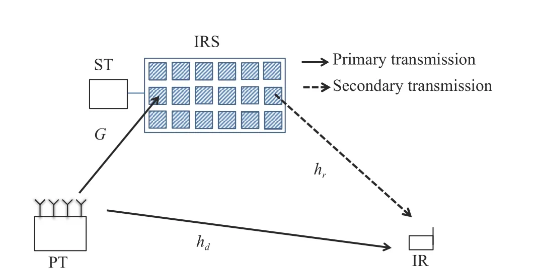
Fig. 1 An IRS assisted SR system
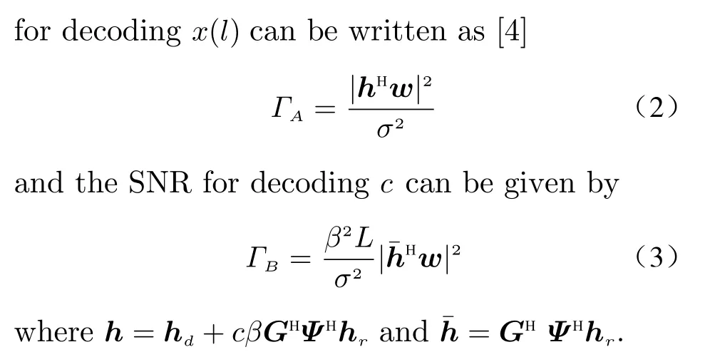
The IRS is powered by the ST. The IRS power consumption is mainly caused by controlling each IRS element [5–7]. On the other hand,the power harvested through PS can reduce the power consumption. Therefore, the IRS power consumption can be expressed as

whereudenotes the power consumption on controlling each IRS element andηdenotes the EH efficiency.
We aim at minimizing the IRS power consumption for the ST while ensuring the QoS of the primary transmission and the secondary transmission by optimizing the transmit beamforming, the reflect beamforming and the PS factor. Based on Eqs.(2)–(4), the transmission optimization problem can be formulated as
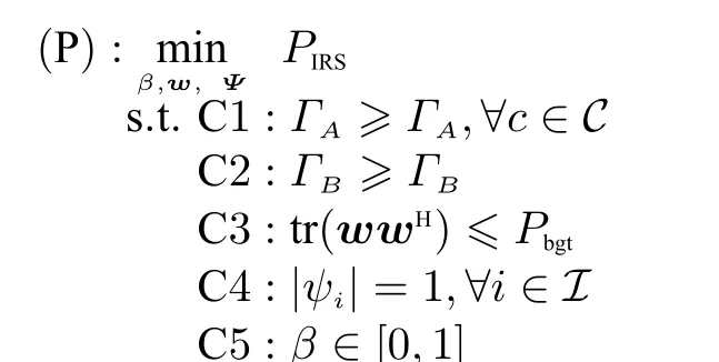
whereΓAandΓBare the SNR requirements of the
primary transmission and the secondary transmission, respectively, andPbgtis the transmit power budget of the PT. In problem (P), C1 and C2 are QoS constrains. C3 is the transmit power constraint. Constraint C4 comes fromψi=ejφiandφi ∈A. Constraint C5 guarantees that the value of the PS factor is between 0 and 1.
3 Transmission Algorithm
The optimization problem (P) is non-convex since the optimization variablesβ,wandΨare coupled in the objective and constraints C1 and C2. In this section, we use the BCD technique to optimize the optimization variables alternatively and propose an efficient optimization algorithm.With fixed PS factorβand reflect beamforming diagonal matrixΨ, the original transmission optimization problem (P) can be simplified into

Problem (P1.1) is still not convex because of the non-convexity brought by constraints C1 and C2. By definingW=wwHand neglect the rankone constraint onW, we can obtain the SDR of problem (P1.1)

Problem (P1.2) is a convex semidefinite programming (SDP) problem and an optimal solution to it can be derived by the interior-point method [10]. However, since the rank-one constraint onWis not considered, solving it does not mean an optimal solution to (P1.1) can be found directly. Therefore, we have the following proposition.
Proposition 1 In problem (P1.2), a rank-one optimal solution can always be constructed,through which an optimal solution to (P1.1) can be obtained, as shown in Algorithm 1.
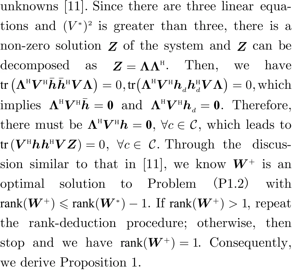
Proof ForW*which is an optimal solution to problem (P1.2), it can be decomposed asW*=V VH,V ∈CN×V*, whereV*=rank(W*).SupposeV*>1. We consider the following system of linear equations

whereZ¯ is a Hermitian matrix with(V*)2
3.1 Transmit Beamforming Optimization
3.2 PS Factor and Reflect Beamforming Optimization
In this subsection, we optimize the PS factorβand reflect beamforming diagonal matrixΨ.With the transmit beamforming vectorwbeing fixed, the original problem (P) can be simplified into

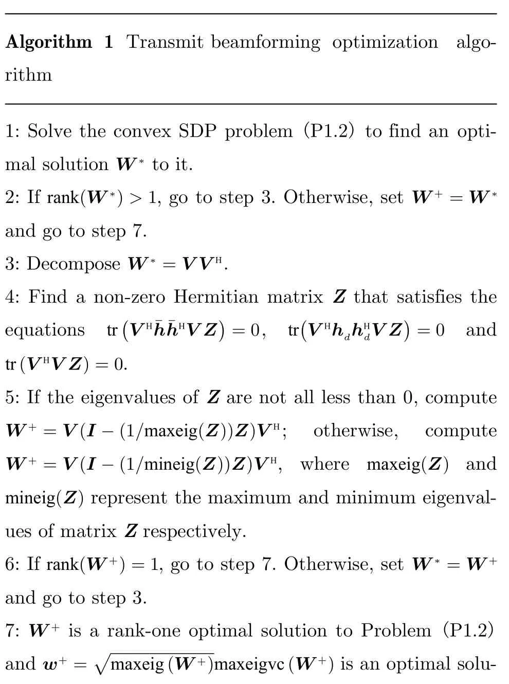
Algorithm 1 Transmit beamforming optimization algorithm 1: Solve the convex SDP problem (P1.2) to find an optimal solution to it.rank(W *)>1 W + =W *W *2: If , go to step 3. Otherwise, set and go to step 7.W * =V V H 3: Decompose .4: Find a non-zero Hermitian matrix Z that satisfies the equations , and.tr(V H¯h¯hHV Z)=0 tr(V HhdhHdV Z)=0 tr(V HV Z)=0 5: If the eigenvalues of Z are not all less than 0, compute; otherwise, compute, where and represent the maximum and minimum eigenvalues of matrix Z respectively.rank(W +)=1 W * =W +W + =V(I -(1/maxeig(Z))Z)V H W + =V(I -(1/mineig(Z))Z)V H maxeig(Z)mineig(Z)6: If , go to step 7. Otherwise, set and go to step 3.7: is a rank-one optimal solution to Problem (P1.2)and is an optimal solu-W +w+ =■maxeig(W +)maxeigvc(W +)

tion to problem (P1.1), i.e, the optimal transmit beamforming vector, where m axeigvc(W +) represents the eigenvector corresponding to the maximum eigenvalue of W +.
In constraints C1 and C2,SandΨare coupled. To decouple the optimization variables, we rewrite (P2.1) as
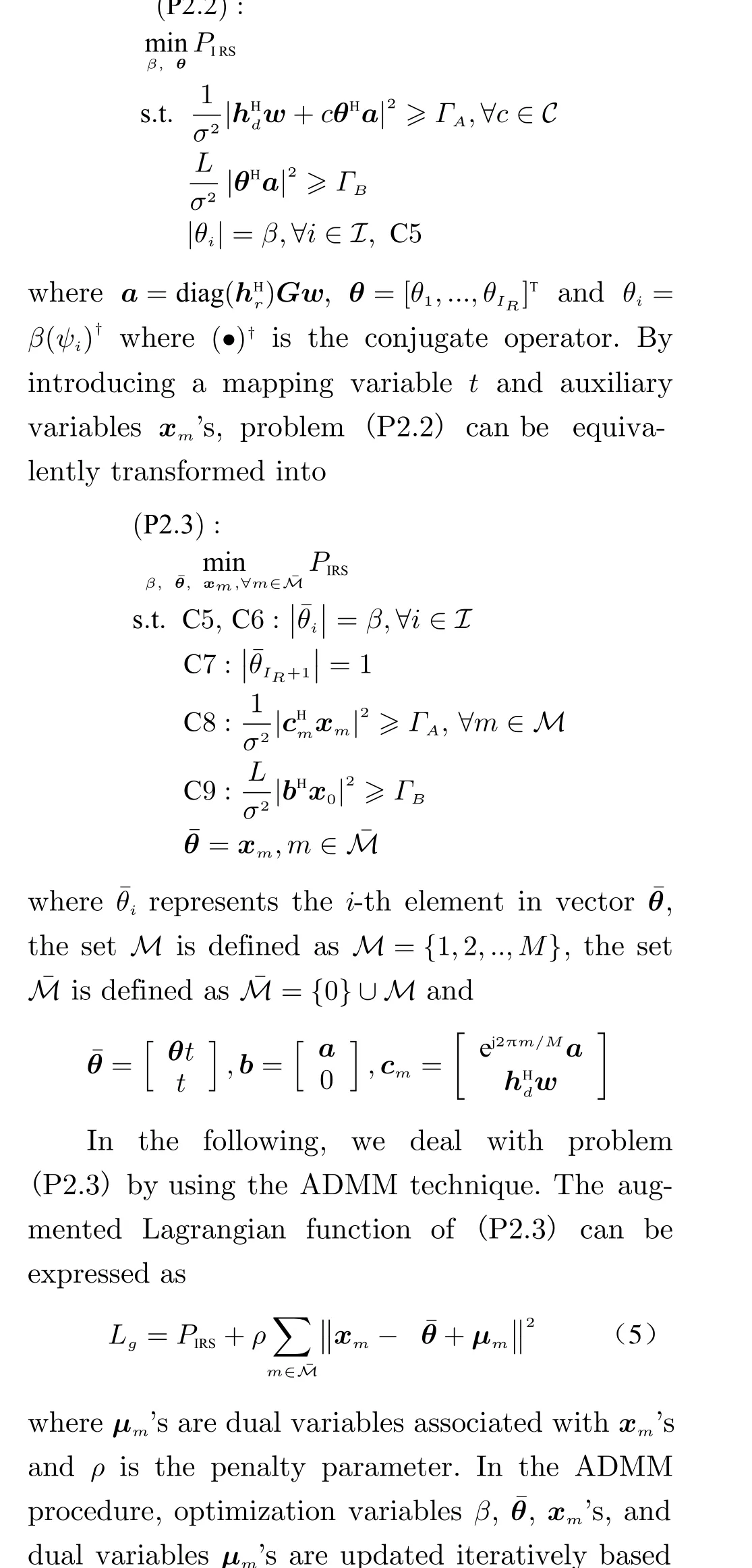

Problem (P2.5) is a convex quadratic programming problem with a linear constraint,through which we have


3.3 Overall Algorithm
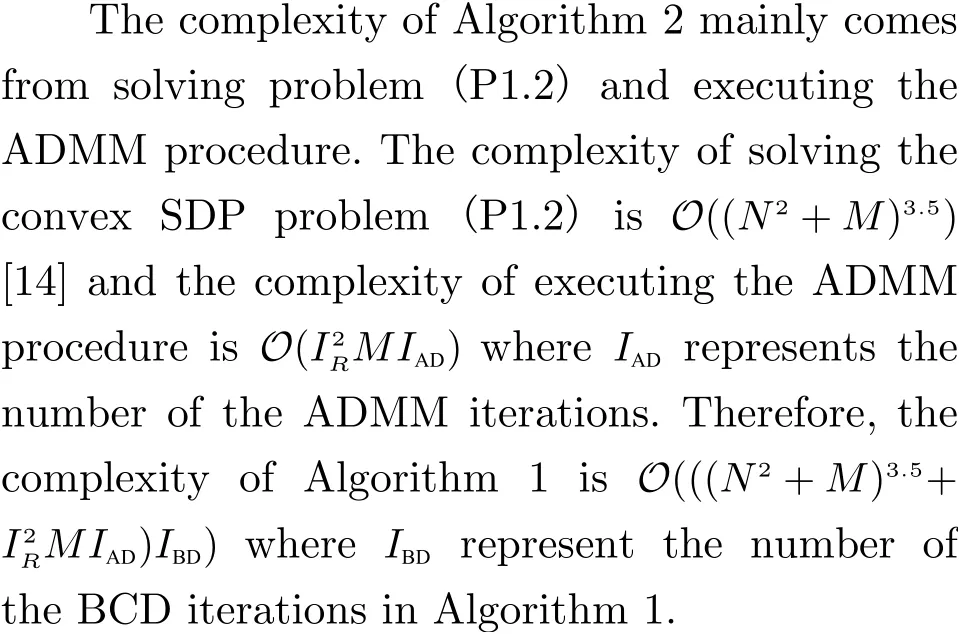
According to the BCD technique, by alternatively optimizing the transmit beamforming vectorw, the PS factorβand the reflect beamforming diagonal matrixΨbased on Sections 3.1 and 3.2, a suboptimal solution to the original transmission optimization problem (P) can be found.The algorithm is summarized in Algorithm 2.Denote the objective value of (P) based on a feasible solution{β,w,Ψ}asfob(β,w,Ψ). Sincew(k+1)is optimal to problem (P1.1) in thek+1-th BCD iteration, there must existfob(β(k),w(k+1),Ψ(k))≤fob(β(k),w(k),Ψ(k)). Iffob(β(k+1),w(k+1),Ψ(k+1))≤f(β(k),w(k+1),Ψ(k))holds (which is
obalways the case), the objective value of (P) can keep nonincreasing in the BCD iterative process.Therefore, the convergence of Algorithm 2 is guaranteed.

Algorithm 2 Transmission optimization algorithm β =1 Ψ =I k =0 1: Initialize , and the index for BCD iterations .w+ w(k+1) =w+w =w(k+1)2: Obtain by execute Algorithm 1; set and fix .n=0 k =0 x(0)3: Initialize the index for ADMM iterations . If, initialize , otherwise,initialize .m =1,μ(0)m =0,∀m ∈ ¯M x(0)m =x+m,μ(0)m =μ+m,∀m ∈ ¯M 4: Update and through (6)-(8).β(n+1) ¯θ(n+1)m ,∀m ∈ ¯M 5: Update through (9) and the correx(n+1)sponding closed form expressions.m ,∀m ∈ ¯M 6: Update through (11).μ(n+1)n=n+1 7: Update .ε=∑m - ¯θ(n)‖2 8: If is small enough, conm∈ ¯M‖x(n)tinue; otherwise, go back to step 4.β+ =β(¯n) ¯θ+ = ¯θ(¯n) x+m =x(¯n)m μ+m =μ(¯n)9: Set , , , ,and, where is the iteration index at which the ADMM procedure converges.β(k+1) =β+ Ψ(k+1) =Ψ+ β =β(k+1)Ψ =Ψ(k+1)m∀m ∈ ¯M Ψ+ =diag((¯θ+1/(β+¯θ+IR+1))†,...,(¯θ+IR /(β+¯θ+IR+1))†) ¯n 10: Set , and fix ,.k =k+1 11: Update .12: If the decrease of the objective value of the original transmission optimization problem (P) is below a predefined threshold, continue; otherwise, go back to step 2.{β(¯k),w(¯k),Ψ(¯k)}13: Output solution and the achieved minimum IRS power consumption, where is the iteration index at which the BCD iterative process stops.IRS =IRu-η(1-(β(¯k))2)tr(Gw(¯k)(w(¯k))HGH) ¯k Pmin
4 Simulation Results

Fig. 2 demonstrates the convergence of the BCD iteration process in the proposed algorithm on one channel realization withΓA=15 dB,ΓB=15 dB and different values ofIR. It can be observed that the BCD process needs only a few iterations to converge. The convergence of the ADMM procedure in the proposed algorithm on three BCD iterations corresponding toIR=40,IR=60 andIR=80 is plotted in Fig. 3. Whenεis close enough to 0, the ADMM procedure converges. One can observe from Fig. 3 that the ADMM procedure converges in tens of iterations.Since closed form solutions are given for the optimization problems occurred in the steps of the ADMM procedure and it converges fast, we know the ADMM procedure can be executed efficiently.

Fig. 2 Convergence of the BCD iteration process with ΓA =15 dB and Γ B =15 dB
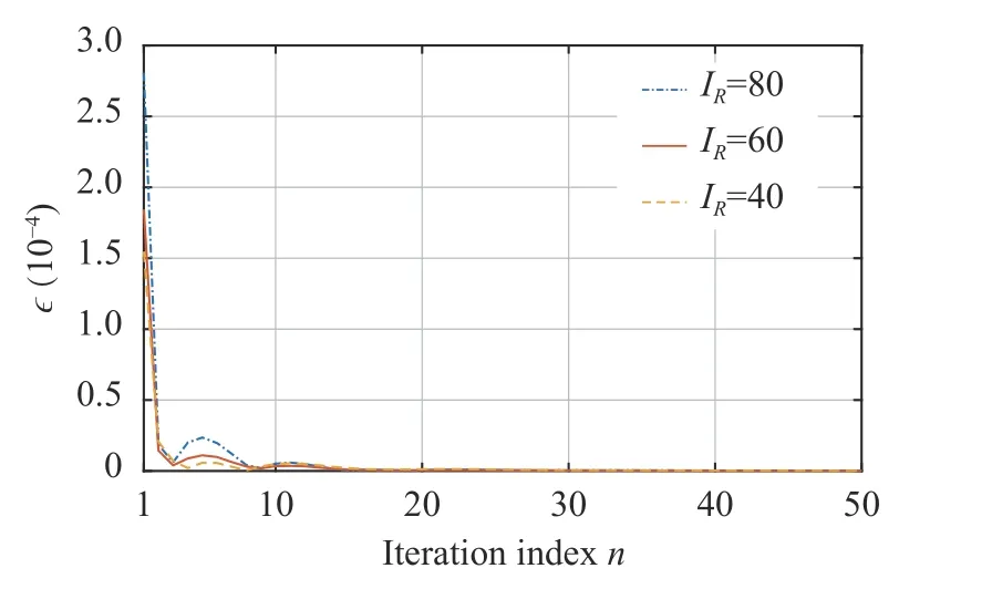
Fig. 3 Convergence of the ADMM iteration procedure with ΓA =15 dB and Γ B =15 dB
For comparison, we also consider the two layer optimization algorithm. In this algorithm,the original transmission optimization problem is solved in two layers. In the inner layer, the transmit beamforming vector and the reflect beamforming diagonal matrix are optimized with fixed PS factor by the SDR-alternating optimization(AO) based approach similar to that in [16]. In the outer layer, the PS factor is optimized by one dimensional line search. The complexity of this algorithm can be given byO(((N2+M)3.5+(IR2+M)3.5)IAOILN) whereIAOandILNdenote the numbers of the AO and the line search iterations.Note that, compared with the number of BCD iterations,ILNis much larger. Compared with that of the proposed algorithm, the complexity of the two layer algorithm is much higher.
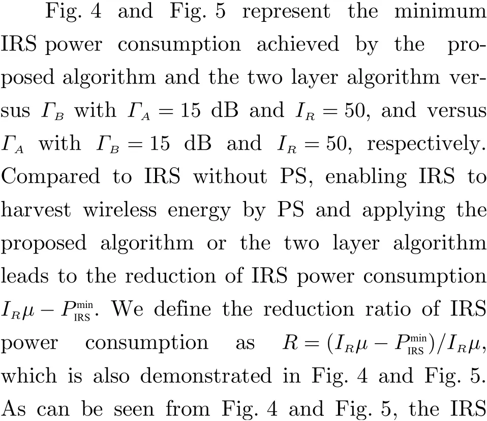

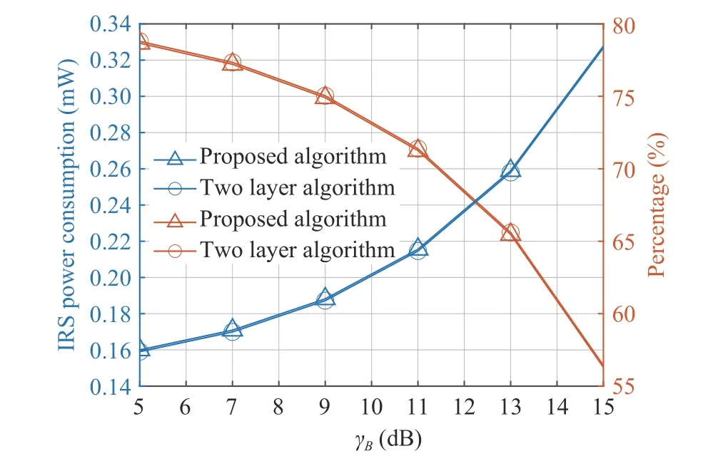
Fig. 4 The IRS power consumption and the ratio R versusΓB with Γ A =15 dB andIR =50

Fig. 5 The IRS power consumption and the ratio R versusΓA with Γ B =15 dB andIR =50
Fig. 6 plots the minimum IRS power consumption the ratioRachieved by the proposed algorithm and the two layer algorithm againstIRwithΓA=15 dB andΓB=15 dB.
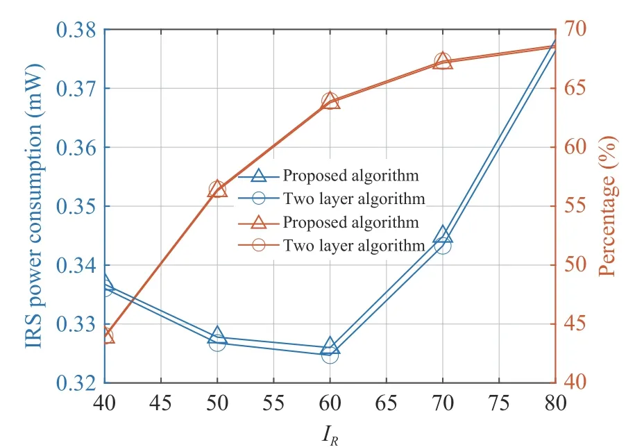
Fig. 6 The IRS power consumption and the ratio R versusIR with Γ A =15 dB and Γ B =15 dB
From Fig. 4–Fig. 6, it can be observed that the proposed algorithm with much lower complexity can perform similar to the two layer algorithm, which demonstrates the effectiveness of the proposed algorithm.
5 Conclusion
In this letter, we considered an IRS with PS assisted SR system and investigated a transmission optimization problem to minimize the IRS power consumption for the ST with QoS constraints. To tackle the optimization problem, we developed an algorithm based on the BCD, SDR and ADMM techniques. Simulation results verified the convergence and effectiveness of the proposed algorithm.
杂志排行
Journal of Beijing Institute of Technology的其它文章
- Resource Allocation for Uplink CSI Sensing Report in Multi-User WLAN Sensing
- A Multi-Vehicle Cooperative Localization Method Based on Belief Propagation in Satellite Denied Environment
- Optimization and Design of Cloud-Edge-End Collaboration Computing for Autonomous Robot Control Using 5G and Beyond
- Optimize the Deployment and Integration for Multicast-Oriented Virtual Network Function Tree
- Performance Analysis for Mobility Management of Dual Connectivity in HetNet
- Symbol Synchronization of Single-Carrier Signal with Ultra-Low Oversampling Rate Based on Polyphase Filter
