Space Elastic Modal Modeling and Control of A New Generation Solid Bundled Rocket
2022-10-29HONGGangXINGaoboLIUYuxiXUEYuSONGPanYANGXinru
HONG Gang ,XIN Gaobo ,LIU Yuxi ,XUE Yu ,SONG Pan ,YANG Xinru
1 Shanghai Academy of Spaceflight Technology,Shanghai 201109
2 Shanghai Institute of Aerospace Systems Engineering,Shanghai 201109
Abstract: In this paper,based upon the characteristics of elastic modal combination of large solid bundled launch vehicles,the finite element theory is used to describe the complex elastic vibration of a solid bundled launch vehicle,and a new three-channel unified elastic vibration equation was established.The elastic vibration equation can reflect the coupling between channels and between boosters and core stage.Some issues need consideration in the theoretical derivation,an engineering application was proposed,and the elastic vibration model was verified.The results of the theoretical derivation and simulation show that the elastic vibration equation of a solid bundled launch vehicle established in the paper is correct and can meet the needs for the engineering application.
Key words: solid bundled rocket,finite element,elastic vibration,coupling
1 INTRODUCTION
In order to carry larger payloads into space,launch vehicles generally use “strap-on technology”,which involves attaching boosters on the core stage to gain greater carrying capacity.In terms of the types of bundling boosters,from the international perspective we can generally adopt two approaches.One is the Russian and Chinese approach,mainly by bundling liquid boosters,such as in Proton and Long March series carrier rockets.The other is the United States,Europe and Japan approach,by bundling solid boosters,such as in Ariane 5 and H-2B launch vehicles.With the development of launch vehicle technology,domestic research on large solid bundled launch vehicle technology has also begun.Compared with the traditional launch vehicles,the main difference of attitude dynamics modeling is the modeling of elastic vibration equation.Due to the characteristics of solid propellant,the elastic vibration equation of the rocket presents a new characteristic,the elastic modes of the rocket appear as cross-coupled.Due to the long length of the solid boosters,the modes reflected by the solid boosters cannot be regarded as local modes in proportion to the full length of the rocket.At the same time,complex local deformation exists.Therefore,the modes for solid propulsion are much more complex than in the single beam model.
In the literature about rocket attitude dynamics modeling,it is generally for series rockets,whose elastic vibration can be divided into longitudinal vibration,torsional vibration and transverse bending vibration,and the coupling among these three vibrations is usually ignored in engineering.There are few papers about attitude dynamics modeling for bundled rockets.Gladkyin his work derived the lateral vibration equation of a cluster missile expressed by a long rod system connected with “B” and “H” type rigid joints.Storeyalso used a similar approach to model the elastic vibration of Hercules-IC rockets.Domestic studies have concentrated on a large bundled launch vehiclein recent years.Paper [7] established an attitude dynamics modeling idea of a large bundled launch vehicle based on the vector mechanics method using mainly the Newton-Euler method rather than specific models.
In view of a large solid bundled rocket,low frequency mode,with complicated local deformation,and the coupling between core stages and boosters,and among channels,using the finite element theory,solid bundled rockets are compared with the equivalent complex elastic vibration of a rigid body,thus establishing the equations of elastic vibration of solid bundled rockets.In this paper,the difference and relation between the elastic vibration equation and the elastic vibration equations of the carrier rockets in service are described,the problems need attention in the process of model derivation are given,and the engineering application method is given.
2 ESTABLISHMENT OF ELASTIC VIBRATION EQUATION
2.1 Coordinate System Definition and Transformation Relationship
In the process of derivation of attitude dynamics model,the coordinate systems mainly used include the launch inertial coordinate system,the rocket coordinate system,the velocity coordinate system,the ballistic coordinate system,the elastic coordinate system and the nozzle coordinate system.The nozzle coordinate system is mainly introduced here,while the other coordinate systems can be referred to in literature.
The nozzle coordinate systemTis fixed to the nozzle of thebooster motor,and the originOis located at the motor swing point.O Xpoints at the head of the rocket along the nozzle symmetry axis.O Zaxis is in the same direction with the rocket body coordinate systemaxis.Assume that the motor’s swing angle aroundO Zaxis isδ,and that aroundO Yaxis isδ.
The force and moment of the rocket are described in the rocket body coordinate system,and the elastic vibration equation is described in the elastic coordinate system,the conversion relationship between the two is:

whereXis the distance between the center of mass and the theoretical tip.
2.2 General Form of Elastic Vibration Equation
The solid-bundled launch vehicle is simplified as multibranch beam model and analyzed by finite element method.First of all,the complete rocket is divided into a number of sites,the position of each site and quality is determined,and then each site is regarded as the beam model of node,the beam element was used to simulate the rocket body stiffness characteristics in the beam element of section.The quality of the structure and the quality of propellant,according to certain rules on both ends of the beam element distribution node,are the established quality unit to simulate quality properties of the rocket.
According to the additional mass method,the stiffness matrix and mass matrix of each element in the local coordinate system are formed respectively.After coordinate transformation,the overall finite element equation of the system is finally formed:

whereis the sum of solid mass and active mass of the rocket,andis the stiffness matrix.The calculation of rocket dynamic characteristics can be summarized in solving the following generalized eigenvalue problems.

where,are eigenvalues and eigenvectors.Solving the frequency equation |-|=0,natural frequencies of the system are obtained.The corresponding modal column vector can be obtained by substituting it into Equation (3).Let=[,,,],called the modal matrix,by the mode superposition method,model node displacement can be expressed as:

where=[,,…,],qis the vibration mode coordinates of order i (or generalized coordinates).
Expandin Equation (2) by Equation (4),and multiply the termsΦon both sides of the equation by the left:

Because the modal has the following orthogonality properties,namely:

SoΦMΦandΦKΦare diagonal matrices,let:

whereξis the mode damping ratio of order.

2.3 Solution of Generalized Force
In this paper,two core stages of the solid-bundled launch vehicle are arranged between the quadrant.The four boosters are uniformly distributed in each of the four quadrant,as shown in Figure 1.Both the core stage engines and the booster motors swing in both directions.In the process of rocket flight,the forces are mainly control force,inertia force,aerodynamic force and so on.
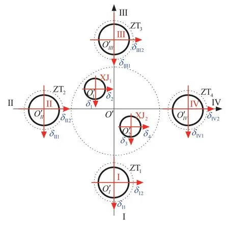
Figure 1 Swing diagram of solid-bundled launch vehicle engines and motors
2.3.1 Generalized force of control force
Generalized force of axial force is as follows:

wherePis core-level thrust,Pis boost thrust,W(x),W(x) are core stage engines and booster motors swing point modes.Generalized forces of bending vibration in pitch plane are:

whereW(x),R(x),W(x) andR(x) are the generalized force and pitch plane of the vibration mode alongand the rotation Angle aroundof the swing point of the core stage engines and the booster motors under the elastic body respectively.The generalized force is symmetric,but it should be noted that it is along the mode ofand the angle around.Generalized force of torsional vibration is as follows.

whereW(x) is the torsion vibration mode of the core stage engine swing point,andis the distance between the core stage engine swing point and the longitudinal axis of the rocket body.
2.3.2 Generalized force of inertia force
The generalized force of pitch plane bending vibration is
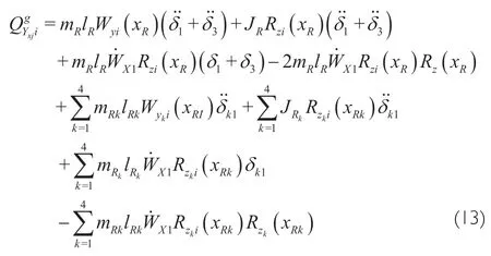
wherem,landm,lare the sway mass and sway length of core stage engines and booster motors respectively.The generalized force of inertia in the yaw plane is symmetric with the generalized force of inertia in the pitch plane,which is omitted here.Generalized force of torsional vibration is

2.3.3 Generalized force of aerodynamic force
The generalized force of the ith-order bending vibration of the pitching plane is:

The generalized force of the ith-order bending vibration in the yaw plane is symmetric with the pitch plane,i.e.angle of attackis replaced by the order of sideslip angle.The generalized force of orderbending vibration of axial force is:

2.3.4 Generalized force formed by aerodynamic damping force
The generalized force of the ith-order bending vibration of the pitching plane is:

The generalized force of the ith-order bending vibration in the yaw plane is symmetric with the pitch plane,that is,the angular velocity of the rocket bodyωis replaced byω.Generalized forces of the first order bending vibration of a rolling channel is:

2.3.5 Generalized force of inertia force of liquid sloshing
Generalized force of first order bending vibration caused by liquid sloshing in pitch plane is:


2.4 Elastic Vibration Equation of Solid-bundled Launch Vehicle
After substituting Equations 10-20 into the right end of Equation (9) and simplifying,the elastic vibration equation of solid bundled rocket can be obtained:

In the expression,the generalized axial,transverse,normal and torsional forces are identified.For the large solid-bundled rocket,it cannot be simply regarded as a one-dimensional beam,its modes are also spatial modes,which can be expressed in any direction in space.These modes include both the modes of core stage and the modes of boosters.Therefore,Equation (21) is the most complete embodiment of the elastic mode of a solid-bundled rocket.

3 DERIVATION OF ELASTIC VIBRATION EQUATION AND ITS ENGINNERING APPLICATION
In derivation and engineering application of elastic vibration Equation (21),attention should be paid to the following problems.The solution to these problems is very important for the correctness of model derivation and corresponding data application,so it needs to be focused on.
3.1 Relationship Between Elastic Angle and Mode Slope
In the derivation of elastic vibration equation,the concepts of elastic vibration mode and rotation angle are needed.In the elastic coordinate system,the mode of vibration represents the translation of the relatively unchanged body,and the rotation angle represents the angle of the relatively unchanged body.In engineering applications,the concept of mode slope is often mentioned.The relationship between rotation angle and mode slope is analyzed below.See Figure 2 and Figure 3.
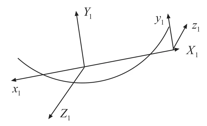
Figure 2 Relationship between vibration mode and rotation angle in pitch plane
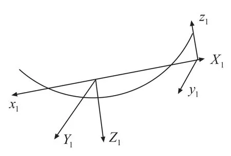
Figure 3 Relationship between vibration mode and rotation angle in yaw plane
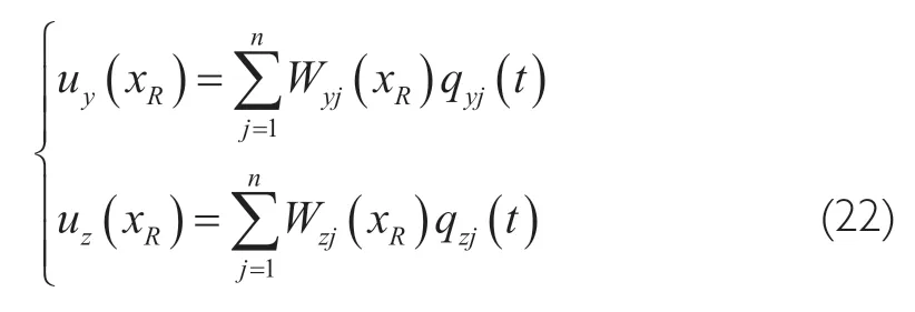
As can be seen from Figure 2,the rotation angle formed around axisisR(x),then the displacement of the formed longitudinal plane isu(x).As can be seen from Figure 3,the rotation angle formed around axis -is -R(x),then the displacement of the formed lateral plane isu(x).The elastic transverse vibration is regarded as the superposition of a series of components,namely:
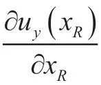
The rotation Angle is expressed as

3.2 Coupling Relation of Elastic Vibration Equation
The elastic vibration Equation (21) deduced in this paper is a general elastic vibration equation.Formally,it contains the elastic vibration equations of pitch,yaw and roll.When the object of study is an unbundled launch vehicle,Equation (21) can be degenerated into three independent elastic vibration equations.When solid thrusters are bundled,elastic coupling between channels,thrusters and core stages is achieved.When analyzing the elastic coupling,the Grignard band graph criterion of inverse Grignard criterion is usually used to judge the coupling between channels.When the coupling is large,the Gerschgorin’s band circle radius is large.On the contrary,the Gerschgorin’s band circle has a smaller radius.In addition,the relative gain array method can also be used to determine the coupling severity of the system,that is,diagonal dominance can be determined by the size of the diagonal value.
As in engineering application,according to the inverse Nyquist criterion,it should first determine the size of the elastic modal coupling,when the coupling is weak,the elastic vibration equation can be simplified as a three-channel independent elastic vibration equation.For larger coupling,it can also be simplified as a three-channel independent elastic vibration equation of the coupled parts which needs to be done as a interference control,for coupling is very big,decoupling control must be used.
4 MODEL SIMULATION VERIFICATION
The correctness of the elastic vibration equation model is the foundation of engineering application.In literature,ADAMS software was used to establish a virtual prototype model reflecting the stiffness,elastic and sway characteristics of the rocket to carry out simulation,and the results were compared with the digital simulation to verify the correctness of the model.This method is a way to verify the model,but it has its limitations.Firstly,the parameters of mathematical simulation are required to be very accurate,and usually accurate parameters can be obtained through modal test.Secondly,it is difficult to simulate the quality change through ADAMS simulation,so it is generally a fixed point simulation.In this paper,another method is used to analyze the elastic coupling of the rocket according to the inverse Nyquist criterion.The analysis shows that there is elastic coupling between the modes,but it is still diagonally dominant.Therefore,the unified vibration equation of the three channels is changed into an independent elastic vibration equation of the three channels.Then,the uniform elastic vibration equation of three channels and the independent vibration equation of three channels are simulated respectively,and the simulation results are compared.Since the independent vibration equation of three channels has been tested by engineering practice,the correctness of the unified vibration equation of three channels can be verified by comparing the simulation results in the case of diagonal dominance.Corresponding simulation results are shown in Figure 4-6.Figure 4 and Figure 5 show the simulation results of the independent elastic vibration equation,and Figure 6 shows the simulation results of the unified elastic vibration equation.Order 1-4 of the unified vibration equation are pitch first order,yaw first order,pitch second order and yaw second order of the independent vibration equation respectively.From the point of view of simulation,the two simulation results are basically consistent.In other words,under the condition of little coupling,the unified elastic vibration equation can be reduced to an independent elastic vibration equation,which verifies the compatibility and consistency of the unified elastic vibration equation and the independent vibration equation of three channels.

Figure 4 Simulation results of pitch channel with independent vibration equation
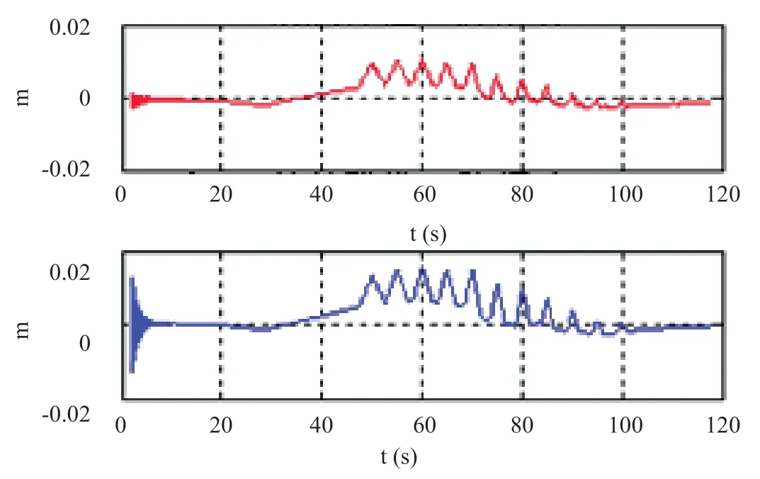
Figure 5 Simulation results of independent vibration equation yaw channel
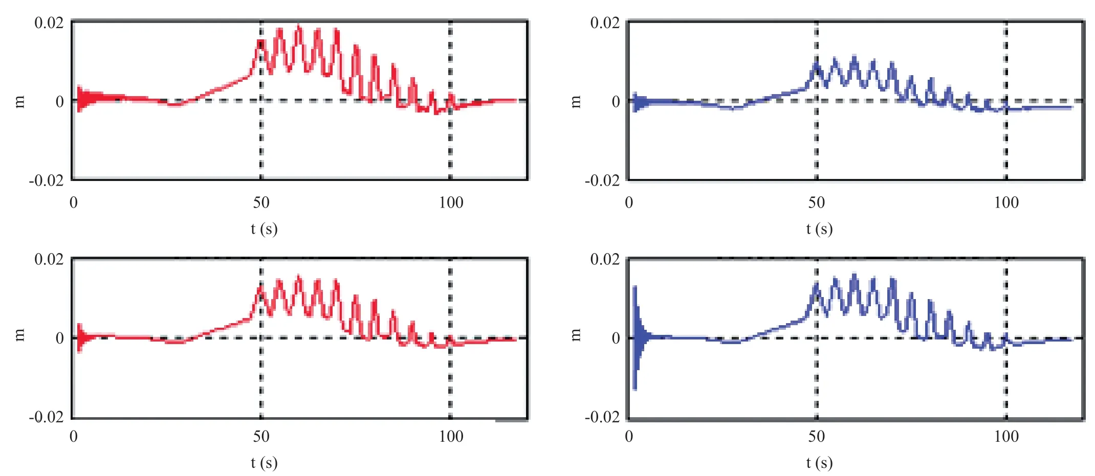
Figure 6 Simulation results of uniform elastic vibration equation of three channels
5 CONCLUSIONS
Based on the finite element theory,this paper describes the complex elastic vibrations of a solid-bundled rocket relative to the equivalent rigid body,and deduces the elastic vibration equation of the solid-bundled rocket.The elastic vibration equation can reflect the coupling between channel and channel and between booster and core stage.The points needing attention in mathematical derivation and engineering application are expounded,and the correctness of elastic vibration equation is verified.
杂志排行
Aerospace China的其它文章
- Long March 6A and Its Technical Characteristics
- Study on the Effect of Solid Particles on Jet Flow and Base Thermal Environment for Solid-Liquid Bundled Rocket
- Research on Modal Test Technology of LM-6A Solid-Liquid Strap-On Launch Vehicle
- Research on Key Technologies of Segmented Solid Rocket Booster
- Research and Application of High-Voltage Power Supply and Distribution on Launch Vehicle
- Application and Research of High-Power Electric Servo System on Launch Vehicle
