Excellent plasma electrolytic oxidation coating on AZ61 magnesium alloy under ordinal discharge mode
2022-10-24WeiyiZhangYunhuiDuPengZhang
Weiyi Zhang,Yunhui Du,Peng Zhang
School of Mechanical,Electronic and Control Engineering,Beijing Jiaotong University,Beijing 100044,China
Abstract In the preparation of plasma electrolytic oxidation (PEO) coating,the rapid heating of freely-happened electron avalanche under traditional discharge (TD) mode inevitably results in a strong eruption of electric breakdown melt.The PEO coating is loose and invariably composed of a very thin inner dense layer and an outer loose layer,as a result of which its properties and application have been limited greatly.In this work,for purpose of weakening the eruption of breakdown melt,thickening the inner dense layer,densifying the outer loose layer and improving the performance of PEO coating,ordinal discharge (OD) mode of PEO coating is developed by regulating the mass ratio of MgF2 to MgO (α) and voltage in the PEO investigation on AZ61 magnesium alloy in KF-KOH electrolyte.The formation mechanism under different discharge mode,electrochemical corrosion and wear of PEO coatings are investigated.The results show that the suitable α and voltage for effective OD are 1.3 and 130V under which the freely-happened electron avalanche in MgF2 under TD mode can be restricted by the adequate adjacent MgO.Compared with TD mode,the inner dense layer,in which the (0) plane of MgF2 is parallel to the (111)plane of MgO at their well-knit semi-coherent interface,is thickened to 2.4~7.2 times,the corrosion potential (Ecorr) improvement is enlarged to 3.6~13.2 times and the corrosion current intensity (Icorr) is reduced from 10.8~9.499 to 0.433 (10-6 A/cm2).The outer loose layer is densified and the wear rate is lessened 65.5%~89.8% by the evident melioration in surface porosity,impedance and hardness.This work deepens the understanding about the discharge of PEO coating and provides an available OD mode for preparing excellent PEO coating.
Keywords: Magnesium alloy;Plasma electrolytic oxidation coating;Ordinal discharge;Microstructure;Performance.
1.Introduction
Magnesium alloy possesses many prominent features,such as low cost,satisfactory recyclability,good mechanical properties,excellent formability,favorable biocompatibility and outstanding biodegradability [1–3],which can meet the needs of numerous fields including automobile,aircraft,computer,communication,biomedicine and so on [4-7].Moreover,this material is considered as the lightest metal structural material and the best candidate for light weighting [8,5,9].Nevertheless,magnesium has high chemical activity and low Pilling-Bedworth ratio which result in the poor corrosion resistance and limit the application of magnesium alloy [2,5,10,11].After decades of painstaking exploration,vast ways like (Zn,Mn,Ga) additives [12-14],extrusion and equal channel angular pressing [15],hydrothermal deposition [16],spraying[17],polymer coating [18],conversion film [19],plasma electrolytic oxidation (PEO) [20-22],etc.are developed to improve the corrosion resistance of magnesium alloy,the corrosion potential(Ecorr)which reflects the possibility of corrosion can be heightened about 30~300mV and the corrosion current intensity (Icorr) which incarnates the rate of corrosion can be cut down from 10-4~10-5to 10-5~10-6(A/cm2).
Among the above ways,PEO is highly favored on account of the strong combination with substrate and the good wear resistance of PEO ceramic coating [1,23,24].Unfortunately,incalculable empty discharge channels generate in the PEO coating owing to the strong eruption of electric breakdown melt resulted from the rapid heating of freely-happened electron avalanche under traditional discharge (TD) mode at high voltage(usually higher than 300V)[25-27].Consequently,the PEO coating is always composed of an outer loose layer and a very thin (0.5~1.5μm) inner dense layer from beginning to nowadays [26-29].As is known to us all,the corrosion resistance of PEO coating mainly depends on the inner dense layer [30].Accordingly,the PEO coating improves the corrosion resistance of magnesium alloy only to a limited extent.To further enhance the corrosion resistance and expand the application of magnesium alloy with PEO coating,surface sealing techniques (sealing discharge holes from the surface of PEO coating) covering chitosan coating,electroless metal plating,high-intensity pulsed ion beam radiation and the like are created,Ecorrcan be increased about 200~1240mV andIcorrcan be dropt from 10-5~10-6to 10-6~10-7(A/cm2)[2,31-33].
From above,it is clear that the strong eruption of electric breakdown melt in the discharge of PEO coating is the root reason for the loose structure and the fundamental obstacle to the development of PEO coating.If the strong eruption of breakdown melt could be weakened,more breakdown melt would be remained in discharge channels,the inner dense layer would be thickened,the outer loose layer would be densified and the performance of PEO coating would be improved.It is well known that the breakdown of PEO coating is that of dielectric [26,27].For the composite dielectric with different dielectric constant under an appropriate voltage,electron avalanche can happen firstly in the dielectric with a small dielectric constant (Ds) meanwhile no electron avalanche occurs in the adjacent dielectric with a large dielectric constant (Dl),that is,the adjacent Dlcan restrict the eruption of Dselectric breakdown melt.Subsequently,after heating by the breakdown melt of Ds,the quick-heated adjacent Dlcan easily conduct electricity without strong eruption [34,35].In other words,under an appropriate voltage,the discharge in composite dielectric is ordinal and the eruption of breakdown melt can be weakened.In this work,ordinal discharge (OD) mode was developed for weakening the eruption of breakdown melt in the PEO investigation on AZ61 in KF-KOH electrolyte by regulating the mass ratio of MgF2to MgO (α) and voltage.The formation mechanism,the electrochemical corrosion and wear resistance of PEO coatings under different discharge mode were investigated.
2.Material and methods
2.1.Materials
AZ61 magnesium alloy (Al 5.8~7.2%,Zn 0.4~1.5%,Mn 0.15~0.5%,Cu≤0.05%,Fe≤0.005%,Si≤0.1%,Ni≤0.005%,Others total≤0.3%,Mg balance,in wt.%) was used to fabricate 60mm×30mm×5mm rectangular specimens,which were then mounted by epoxy resin with an exposed area of 20mm×20mm respectively.Each exposed area must be ground with SiC abrasive papers to 2000 grit,cleaned with CH3COCH3and dried in warm air.KF·2H2O,KOH,distilled water,etc.were adopted to prepare a room-temperature (22°C) KF-KOH electrolyte.
2.2.Preparation of PEO coating and ordinal discharge(OD) thought
2.2.1.PEO setup
Fig.1 gives the schematic diagram of PEO setup.A Matsusada PKT-650–5 regulated DC power supply and a controlling system were employed to supply power and measure current waveform under constant voltage mode.A 20L stainless steel container was used to contain the electrolyte and served as cathode while the specimen served as anode.The O2spray nozzle was utilized to pump O2bubbles into the electrolyte at a rate of 0.01L/s.The purpose of pumping O2bubbles is to form an O2film on the sample surface prior to switching on the power.This O2film can guarantee the PEO on the sample surface via microdischarge as soon as switching on the power [36].To maintain the concentration of electrolyte in container,the electrolyte with required concentration was poured into the container via the entrance from the electrolyte trough and drained out via the exit into the recycle trough at a rate of 0.1L/s.To hold the temperature of electrolyte in container,namely,to drain out the hot electrolyte in time,the distance between specimen and exit was fixed at 20mm.
2.2.2.PEO operation
PEO operation was as follows.After pumping O2for 1min,the 20mm×20mm exposed area of specimen was completely immersed in the electrolyte.After another 1min for O2to accumulate over the exposed area,the power under a constant voltage was switched on to carry out PEO[36].After PEO,the specimen was cleaned ultrasonically with CH3COCH3,rinsed with distilled water and dried in warm air.
2.2.3.Components of PEO coating and their mass ratio α
In this PEO system,the following reactions will proceed on the specimen [36,37]:
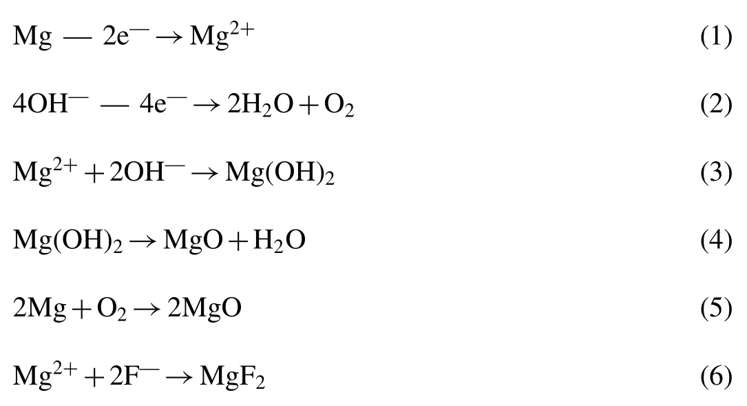
It can be seen that MgF2and MgO are the final products and hence the mass ratio of MgF2to MgO(α)of PEO coating
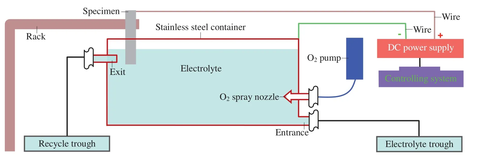
Fig.1.Schematic diagram of PEO setup.

Fig.2.Different discharge mode: (a) Freely-happened electron avalanche under TD mode;(b) Loose PEO coating;(c) Restricted electron avalanche under OD mode;(d) Densified PEO coating.
can be controlled by adjusting the KF·2H2O and KOH concentration.According to Reference [38],αcan be acquired by

2.2.4.Ordinal discharge (OD) thought
In the traditional PEO treatment,the applied voltage is usually higher than 300V [26,27].In this case,the electron avalanche happens freely in each component of PEO coating during discharge and its rapid heating results in a strong eruption of electric breakdown melt (Fig.2a).Thus an outer loose layer and a very thin inner dense layer generate in the PEO coating under this traditional discharge (TD) mode(Fig.2b) [39].
In this work,for the PEO coating with a suitableα(that is,composed of proper MgF2and MgO),the electron avalanche will firstly happen in MgF2(with a small dielectric constant of 5.45) meanwhile no electron avalanche occurs in the adjacent MgO (with a large dielectric constant of 9.7) at an appropriate voltage.Under this circumstance,the adequate adjacent MgO can restrict the electron avalanche in MgF2and hence the eruption of MgF2electric breakdown melt resulted from the rapid heating of electron avalanche is weakened (Fig.2c).Thereafter,the high-temperature adjacent MgO (heated by the MgF2breakdown melt) can easily conduct electricity without strong eruption under the action of electric-thermal coupling field [34,35].It is obvious that,under this MgF2-MgO OD mode,more breakdown melt will be remained in discharge channels and,as a consequence,the inner dense layer can be thickened and the outer loose layer can be densified(Fig.2d).This is the OD thought for weakening the eruption of breakdown melt and densifying the PEO coating by regulatingαand voltage.
2.3.Microstructure and compositional analysis
A JEOL JSM-5600 scanning electron microscope coupled with EDS (operating at 20kV),a M18XHF-SRA Xray diffractometer (operating at 40kV,using Cu Kαradiation(λ=0.154nm)) and a FEI Tecnai F30 high-resolution transmission electron microscope coupled with EDS (operating at 300kV) were employed to investigate the microstructure and composition of PEO coatings.The cross-sectional SEM samples were cleaned ultrasonically with CH3COCH3after being mounted into epoxy resin,ground with SiC abrasive papers to 2000 grit,polished with diamond paste to 1μm and sputtered with a gold coating using a Model 682 Gatan Precision Etching Coating System.The surface porosity of PEO coating was ascertained from 5 randomly-selected fields of view by image analysis using the Quantimet 520 Image Processing and Analysis System.Before XRD,the PEO coating was first scraped down by mechanical method and then ground into powder with agate bowl in order to eliminate the effect of surface discharge holes.In XRD testing,the detected angle (2θ) of XRD was scanned from 20° to 70° at a speed of 1o/min.For TEM and HRTEM,the samples were firstly ground to about 300μm,then polished to 100μm,subsequently dimpled to a remaining thickness of about 25μm and lastly ion-beam milled/polished into foils using a GATAN PIPS.All results are the average of 5 values.
2.4.Performance testing
2.4.1.Electrochemical measurement
CHI660E electrochemical workstation was utilized to evaluate the electrochemical corrosion behavior of specimen.Potentiodynamic polarization measurement and electrochemical impedance spectroscopy (EIS) were conducted in 3.5wt.%NaCl solution (pH 7.0) at room temperature (22 °C) using a conventional three-electrode cell with bare AZ61 or PEO treated specimen as the working electrode (with an exposed area of 10mm×10mm),a saturated calomel electrode (SCE)as the reference electrode and a platinum plate as the counter electrode.An initial 30min delay was needed to stabilize the open circuit potential.In potentiodynamic polarization,the scanning rate was 0.5mV/s from -250mV to 250mV vs the open circuit potential.In EIS,the frequency range was from 100kHz to 10 mHz and the amplitude of sinusoidal potential signal was 5mV vs the open circuit potential.The EIS data were analyzed by ZView2 software.
2.4.2.Wear and hardness testing
A ball-on-disc tribometer (CSM Instruments) was used to estimate the wear resistance of sample in atmosphere at room temperature.The humidity was 35~40%.The balls were ZrO2ceramic balls with a diameter of 5.99mm.The counterparts were the polished discs made of the bare AZ61 and PEO treated specimen (Ra0.1μm).For the PEO treated specimen,the PEO coatings with a thickness of 40μm were adopted.To exclude the influence of surface roughness,the coatings were ground and polished (Ra0.1μm) to a thickness of about 30μm.The wear conditions included 20mm for track diameter,5.5N for normal load,300rpm for rotating rate and 10min for sliding time.Wear ratekwas determined by Archard equation [40]

Where the total wear volumeV=πdS,dis the wear track diameter,Sis the cross-sectional area of each wear track which is identified by a surface profilometer (TR200),Fis the normal load andlis the entire sliding distance.A micro Vickers hardness tester(TMVS-1,TIMES Group)was applied to assess the hardness of PEO coating.A load of 100g was exerted to the specimen for 15s.All results are the average of 5 values.
3.Results and discussion
3.1.Ordinal discharge (OD) mode of PEO coating
3.1.1.Mass ratio of MgF2 to MgO (α) of PEO coating
Fig.3a–c presents the 3D surface and profile lines(CKOH=KOH concentration=5g/L andCKF·2H2O=KF·2H2O concentration=100g/L) of the KF-KOH electrolyte concentration and the correspondingα(acquired by Eq.(7)) of PEO coating at voltage=130V andTt(treatment time)=6min.Fig.3d–f displays the 3D surface and profile lines(voltage=130V andTt=6min) of the voltage,Tt and the correspondingαatCKOH=5g/L andCKF·2H2O=100g/L.Fig.3g gives the XRD patterns of typical PEO coatings which are composed of MgF2and MgO.It can be seen that the voltage andTt have little effect onαat 110~165V and 6~10min and theαof PEO coating can indeed be controlled by adjusting the KF·2H2O and KOH concentration.
The influence mechanism of KF-KOH electrolyte concentration onαof PEO coating can be explained as follows.Under the sameCKOHe.g.5g/L Fig.3b),asCKF·2H2Oincreases from 40g/L to 140g/L,moreF-participates in reaction.From Eq.(6),more MgF2forms and thusαenlarges from 1 to 10.7.Similarly,under the sameCKF·2H2Oe.g.100g/L (Fig.3c),asCKOHenhances from 5g/L to 20g/L,more OH-gets involved in reaction.From Eqs.(2)–((5),more MgO generates and thusαreduces from 5.1 to 0.6.Accordingly,the PEO coatings with differentαcan be prepared by adjusting the KF·2H2O and KOH concentrations.
3.1.2.α and voltage for effective od
Fig.4a–c exhibits the 3D surface and profile lines(voltage=130V andα=1.3)ofL(the thickness of inner dense layer,i.e.,the smallest distance from the tip of discharge channel to the coating-substrate interface),αand voltage.Fig.4d–f shows the cross-sectional morphologies of typical PEO coatings withα=0.1,10.7 and 1.3 (40μm-thick and the treatment conditions are shown in Table 1),separately.It is clear that the coatings are composed of an outer loose layer and an inner dense layer just as the traditional ones [28,29].Under an extremeα(0.1 or 10.7) or too large voltage (165V),Lis 1.1~1.4μm (the purple area in Fig.4a) which is similar to that (0.5~1.5μm) of traditional ones (Table 2).However,underα=1.3 and 130V,Lhas the largest value 3.6μm(Figs.4a–c) which is 2.4times as thick as the traditional ones (Table 2).

Table 1 Treatment conditions for the 40μm-thick typical PEO coatings with different α.

Table 2 Inner dense layer thickness of the typical experimental and traditional PEO coatings.

Fig.3.(a)–(f) 3D surface and profile lines of α and treatment conditions;(g) XRD patterns of typical PEO coatings with α=0.1,1.3 and 10.7,respectively.
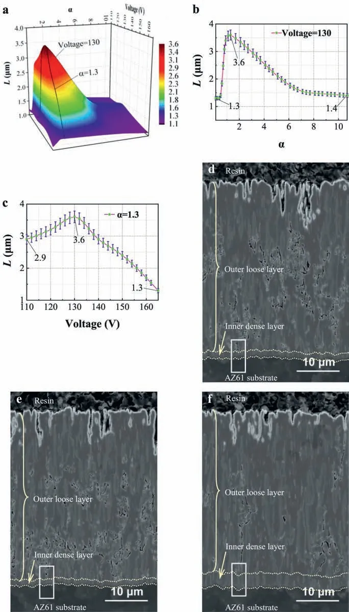
Fig.4.(a)–(c) 3D surface and profile lines of L (thickness of inner dense layer), α and voltage;(d)–(f) Cross-sectional morphologies of typical PEO coatings with α=0.1,10.7 and 1.3,separately.

Fig.5.(a)–(c) 3D surface and profile lines of surface porosity of PEO coatings, α and voltage;(d)–(f) Surface morphologies of typical coatings with α=0.1,10.7 and 1.3,respectively.
Fig.5a–c presents the 3D surface and profile lines(voltage=130V andα=1.3) of the surface porosity of PEO coatings,αand voltage.Fig.5d–f provides the surface morphologies of typical PEO coatings withα=0.1,10.7 and 1.3,respectively.It can be seen that the crater-shaped discharge holes,which indicate the icon of PEO,distribute on the scraggly surface of coatings just as the traditional ones[28,29].For the coating underα=1.3 and 130V,the craters are apparently smaller than those under an extremeα(0.1 or 10.7) or too large voltage (165V) and the surface porosity (3.37%) is reduced by 68%
Fig.6a–b displays the current density with treatment time at 130V for differentαand that forα=1.3 at different voltage,respectively.Fig.6c shows their current waveforms.It is obvious that the current waveforms are approximately periodic waveforms when the current density completely stabilize after 360s.Under an extremeα(0.1 or 10.7) or too large voltage (165V),one process of discharge “1” displays in one cycle of current waveforms 1○,2○and 5○(Fig.6c),which is in agreement with traditional discharge (TD) mode[42].However,under a suitableα(1.3) and voltage (110 and 130V),two sequentially occurring processes of discharge “1”and “2” appear in one cycle of current waveforms 3○and 4○(Fig.6c),which visually embodies the ordinal discharge(OD) mode.

Fig.6.(a) Current density vs treatment time at 130V for different α;(b) Current density vs treatment time for α=1.3 at different voltage;(c) Current waveforms corresponding to the discharge of (a)–(b) after 360s in steady state.
From the above,the PEO coating has the largestL(3.6μm),smaller crater and lower surface porosity(3.37%) atα=1.3 and 130V under OD mode.Accordingly,the suitableαand voltage for effective OD in PEO treatment on AZ61 in KF-KOH electrolyte are 1.3 and 130V.
3.1.3.Formation mechanism of PEO coatings under different discharge mode
In this investigation,an O2film has accumulated on the sample surface prior to switching on the power.Thus PEO happens on the sample surface via microdischarge as soon as switching on the power Fig.7a),a plasma thin coating firstly forms (Fig.7b) and then the PEO coating generates gradually via Eqs.(1)–((6) [36].In the discharge of PEO coating,the rapid heating of electron avalanche can cause an eruption of breakdown melt from discharge channel into electrolyte(Fig.7c) [39].Accordingly,the craters distribute at the scraggly surface(Figs.5d–f,Fig.7d)of coating which is composed of an outer loose layer and an inner dense layer (Figs.4d–f,7d) [43,44].
As for the typical PEO coating withα=0.1 or 10.7,which is mainly composed of MgO or MgF2(Fig.8a–b,d–g),it can be approximately considered as single dielectric whose electric breakdown will occur under the following conditions[45]


Fig.7.Formation mechanism of PEO coatings under different discharge mode: (a)–(d) Formation of PEO coating;(e)–(f) PEO coating with α=0.1 or 10.7 under TD mode;(g)–(h) PEO coating with α=1.3 at 130V under OD mode;(i)–(j) PEO coating with α=1.3 at 110V under OD mode;(k)–(l) PEO coating with α=1.3 at 165V under TD mode.
WhereVB,c,ρandJare the breakdown voltage,electrolyte concentration,electrolyte resistivity and electronic current density,respectively.The others are the constant values.Under this TD mode,the electron avalanche can happen freely (Fig.2a) and hence one process of discharge “1” displays in one cycle of current waveforms 1○and 2○at 130V(Fig.6c) and bulk MgO or MgF2grows into the AZ61 substrate simultaneously (Figs.9a–b,f–i).In this case,the rapid heating of freely-happened electron avalanche can cause a strong eruption of electric breakdown melt (Fig.7e).Therefore the typical PEO coating withα=0.1 or 10.7 has larger surface craters,a large surface porosity (7.56~10.53%) and a thin inner dense layer (1.3~1.4μm,comparable to that 0.5~1.5μm of traditional PEO coatings,Figs.4a–b,d–e,5a–b,d–e,Table 2,Fig.7f).

Table 3 Potentiodynamic polarization data of samples.

Fig.8.Compositional analysis of inner dense layer: (a)–(c) Magnified images of the white frames in Figs.4d–f,separately;(d)–(i) F and O maps of (a)–(c),respectively.

Fig.9.(a)–(c) TEM images of inner dense layer-substrate interface at 130V for α=0.1,10.7 and 1.3,separately;(d)–(e) TEM images of inner dense layer-substrate interface for α=1.3 at 110 and 165V,separately;(f)–(o) F and O maps of (a)–(e),respectively.
With regard to the typical PEO coating withα=1.3,MgF2and MgO mix alternately (Fig.8c,h–i).The dielectric constant of MgF2(5.45) is smaller than that of MgO (9.7),the electron avalanche can happen firstly along MgF2at an appropriate voltage (such as 130V),meanwhile no electron avalanche occurs in the adjacent MgO which can restrict the electron avalanche of MgF2(Fig.2c).Under the circumstances,the eruption of MgF2electric breakdown melt is directly weakened.Moreover,after heating by the MgF2breakdown melt,the quick-heated adjacent MgO begins to discharge under the action of electric-thermal coupling field according to [34,35]

whereEis the electric intensity,Tis the absolute temperature,aandbare the constant values,Iis the current density,ΔVis the potential barrier,his the Planck constant,ρis the dielectric density,v0is the elementary cell volume,csis the sound speed in dielectric,eis the electron charge,δis the dielectric sample thickness,gis the coupling constant,Sis the breakdown surface area andmis the electron mass.It can be seen that the high-temperature adjacent MgO can easily conduct electricity after heating by the MgF2breakdown melt.That is to say,the discharge mode presents as MgF2-MgO OD mode.On one hand,two sequentially occurring processes of discharge “1” and “2” appear in one cycle of current waveform 3○(Fig.6c)and the bulk MgF2protrudes into the AZ61 substrate at the inner dense layer-substrate interface owing to the prior discharge of MgF2(Fig.9c,j–k).On the other hand,the eruption of breakdown melt weakens(Fig.7g),Lincreases(3.6μm,Figs.4a–b,f,Fig.7h) and the surface porosity decreases (3.37%,Figs.5a–b,f,7h).In the case of a low voltage (such as 110V),two sequentially occurring processes of discharge “1” and “2” also occur in one cycle of current waveform 4○(Fig.6c) and the bulk MgF2also protrudes into the AZ61 substrate (Fig.9d,l–m),which indicate the existence of MgF2-MgO OD.Since the eruption of breakdown melt will weaken at a lower voltage (Fig.7i),the surface porosity minifies (2.93%,Figs.5a,c,7j).Nevertheless,MgF2and MgO produced according to Reactions(1)-(6)also lessen.ThusLdiminishes at 110V (2.9μm,Figs.4a,c,7j).As for a high voltage (such as 165V),one process of discharge “1”displays in one cycle of current waveform 5○again (Fig.6c)and the bulk MgF2and MgO grow into the AZ61 substrate shoulder to shoulder (Fig.9e,n–o) just as those resulted from electric breakdown under TD mode (Fig.9a–b,f–i).This illustrates the electron avalanche proceeds simultaneously in the bulk MgF2and MgO at high voltage and the restriction of bulk MgO to electron avalanche vanishes,namely,the discharge mode returns to TD mode again (Fig.7k).Consequently,Lreduces (1.3μm,Figs.4a,c,7l) and the surface porosity enlarges at a high voltage (5.78%,Figs.5a,c,7l).
On the whole,only under suitableαand voltage,the eruption of breakdown melt could be weakened by restricting the electron avalanche and OD could work effectively in the PEO treatment.The discovery of OD provides a new idea for densifying PEO coating.Under the MgF2-MgO OD mode in PEO treatment on AZ61 in KF-KOH electrolyte,Lcan beenlarged to 3.6μm which is 2.4~7.2 times as thick as that under TD mode and the surface porosity can be reduced by 68%.It can be seen that OD does play an important role in densifying PEO coating.
3.2.Electrochemical corrosion resistance
Fig.10a and Table 3 give the electrochemical corrosion resistance of the bare AZ61 and typical PEO treated samples (with 40μm-thick PEO coatings and the treatment conditions are shown in Table 1).It is apparent thatEcorrof AZ61 substrate is enhanced andIcorris lessened by the PEO coatings.For the PEO coatings under TD mode,the improvement ofEcorr(300~303mV) forα=0.1 and 10.7 is similar to that (110~400mV) of traditional PEO coatings (Table 4).However,the improvement(1456mV)forα=1.3 at 130V under OD mode is 3.6times as large as that of coatings under TD mode.Correspondingly,the lowest value ofIcorr(0.433×10⁻⁶A/cm2) is also got forα=1.3 at 130V under OD mode (Table 3).It can be said that the PEO coating withα=1.3 at 130V under OD mode possesses outstanding electrochemical corrosion resistance.
Fig.10b-d shows the equivalent circuit,frequencyimpedance and frequency-theta plots of PEO treated samples.Table 5 exhibits the data of EIS.It is observed that,for the coatings with same thickness (40μm) and differentα,asα=0.1 (mainly composed of MgO) or 10.7 (mainly composed of MgF2),Rdl(impedance of the inner dense layer)for a 1.3~1.4 (Table 2) μm-thick inner dense layer has a change from 4.5285 to 5.934 (105Ωcm2) with the increasing ofLandRll(impedance of the outer loose layer) for a 38.7 (=40–1.3)~38.6 (=40–1.4) μm-thick outer loose layer is almost the same (10,318~10,359Ωcm2),as a result of which theEcorr (-1612~-1609mV) andIcorr (10.8~9.499 10-6A/cm2) change very little.This means that the content of MgO and MgF2has little impact on the corrosion protection of PEO ceramic coating.According to Reference 35,the corrosion resistance of PEO coating strongly depends on the inner dense layer.From Table 5,it can be seen that the PEO coating withα=1.3 at 130V under OD mode has an inner dense layer with an extreme largeRdlwhich is 8.7times as large as those forα=0.1 and 10.7 under TD mode.This is the main reason for the outstanding electrochemical corrosion resistance of PEO coating withα=1.3 at 130V under OD mode,which can be further explained as follows.1○According to Fig.4 and Table 2,Lis enlarged from 1.3~1.4μm forα=0.1 and 10.7 under TD mode to 3.6μm under OD mode,by whichRdlcan be naturally increased.2○On the basis of Figs.8c,j–k and 10e-f,it is clear that MgO nanoparticle distributes in bulk MgF2,likewise,MgF2nanoparticle distributes in bulk MgO.Moreover,the (0) plane of MgF2is parallel to the(111) plane of MgO whether between the bulks or between the bulk and nanoparticle.The interplanar spacing of (0)planes in MgF2is 0.255nm while that of(111)planes in MgO is 0.242nm,i.e.,the lattice misfit is 0.013nm which results in a well-knit semi-coherent interface.This well-combined interface guarantees the inner layer truly dense.Accordingly,the improvement ofEcorrforα=1.3 at 130V under OD mode is largely enhanced to 1456mV andIcorris lessened to the lowest value 0.433×10⁻⁶A/cm2by the thickened inner dense layer.
3.3.Wear resistance
Table 6 presents the wear rate of typical experimental and traditional PEO coatings.It is obvious that the wear rate 921(10-5mm3/N·m) of AZ61 is reduced by the PEO coatings.For the coatings under TD mode,the wear rate 1.89~2.61(10-5mm3/N·m) forα=0.1 and 10.7 is equivalent to the best value 1.48~5 (10-5mm3/N·m) of traditional PEO coatings(Table 6).Nevertheless,the wear rate forα=1.3 at 130V under OD mode is only 0.51(10-5mm3/N·m),that is,the best value of traditional PEO coatings under TD mode is reduced 65.5%It can be asserted that the PEO coating withα=1.3 at 130V under OD mode has excellent wear resistance.
As we know,the wear of PEO ceramic coating happens mainly on its outer loose layer and hence the wear resistance of coating prominently rests with the outer loose layer.In the sliding wear,the wear loss is inversely proportional to compactness and hardness [49].In line with Fig.5d–f and Table 5,the PEO coating withα=1.3 at 130V under OD mode has a densified outer loose layer with a small surface porosity and a large impedanceRllwhich is 130.7%as large as those forα=0.1 and 10.7 under TD mode.From Fig.11a,all PEO coatings enlarge the hardness (61.5 HV) of AZ61 substrate and the largest value (341.1 HV) is got forα=1.3 at 130V under OD mode.Thus the large wear rate 921 (10-5mm3/N·m) of AZ61 (corresponding to the coarse wear tracks in Fig.11b) is reduced to 1.89~2.61 (10-5mm3/N·m) by the coatings withα=0.1 and 10.7 (corresponding to the slight wear tracks in Fig.11c and e) and to 0.51 (10-5mm3/N·m) by the coating withα=1.3 (corresponding to the tiny wear tracks in Fig.11d),that is to say,the PEO coating withα=1.3 at 130V under OD mode also has an excellent wear resistance.It can be concluded that this investigation presents an OD mode for densifying PEO coating and improving performance,and will advance the development of PEO coating on magnesium alloy.

Table 4 Ecorr improvement of substrate by the typical experimental and traditional PEO coatings.

Table 5 EIS data of the PEO treated samples.

Table 6 Wear rate of the typical experimental and traditional PEO coatings.
4.Conclusions

Fig.10.(a) Potentiodynamic polarization curves;(b) Equivalent circuit;(c) Frequency-impedance plots;(d) Frequency-theta plots;(e)–(g) HRTEM images at points 1 (in bulk MgF2),2 (in bulk MgO) and 3 (at bulk MgF2-bulk MgO interface) in Fig.9c,respectively,and the corresponding SAED patterns of MgF2,interface and MgO green square areas.
In this work,ordinal discharge (OD) mode for weakening eruption of breakdown melt,densifying coating and improving performance is developed by regulating the mass ratio of MgF2to MgO (α) and voltage in the PEO investigation on AZ61 in KF-KOH electrolyte.The conclusions are summarized as follows:
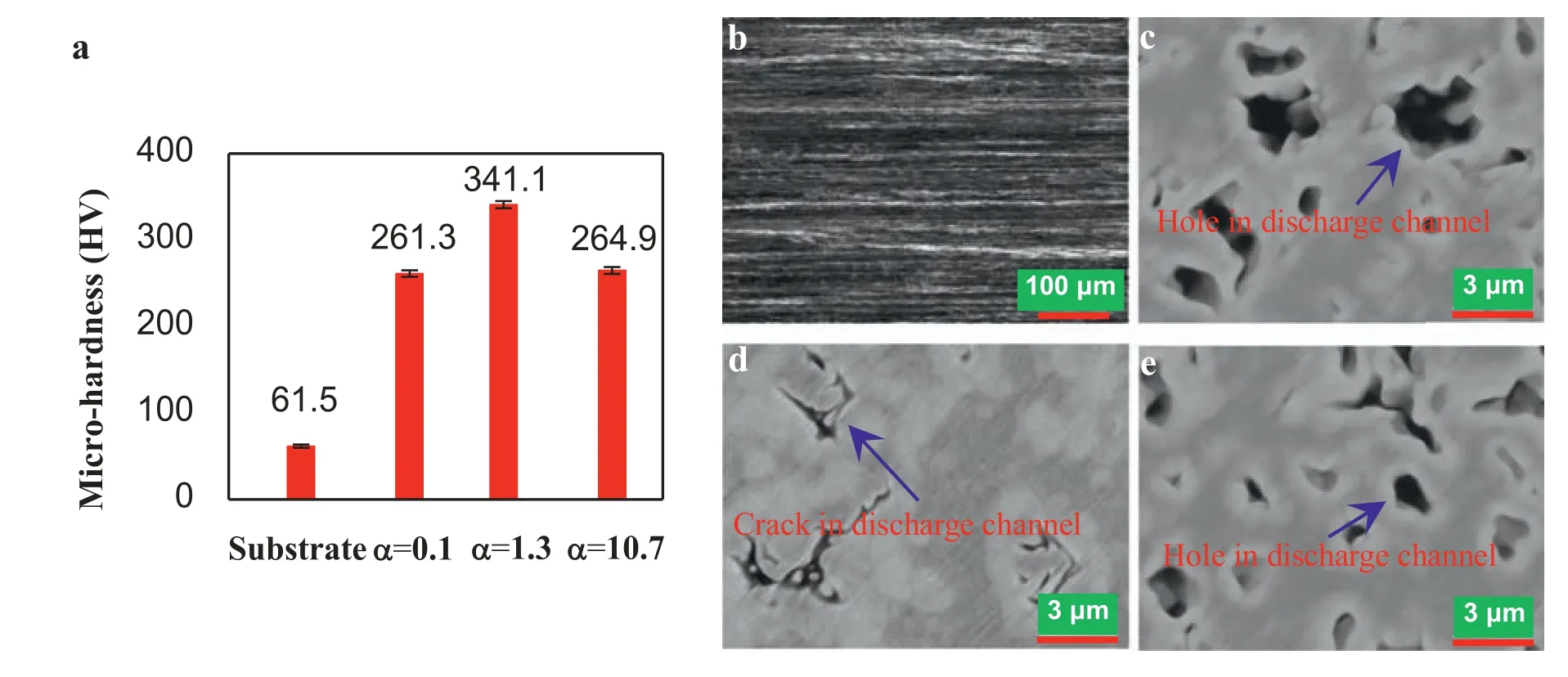
Fig.11.(a) Micro-hardness of the bare AZ61 and PEO treated samples;(b)–(e) Typical worn surfaces of the bare AZ61 and PEO coatings with α=0.1,1.3 and 10.7,respectively.
(a) The feasible conditions for OD and the formation mechanism of PEO coatings under different discharge mode are clarified.The suitableαand voltage for effective MgF2-MgO OD are 1.3 and 130V.Under this OD mode,the freely-happened electron avalanche under traditional discharge (TD) mode can be restricted,the eruption of breakdown melt can be weakened and the PEO coating can be densified.In comparison with TD mode,the thickness of inner dense layer (L) can be enlarged to 2.4~7.2 times and the surface porosity can be reduced by 68%.
(b) The PEO coating withα=1.3 at 130V under OD mode has an outstanding electrochemical corrosion resistance.Compared with the PEO coatings under TD mode,theEcorrimprovement is enlarged to 3.6~13.2 times and theIcorris reduced from 10.8~9.499 to 0.433 (10-6A/cm2)by the thickened inner dense layer in which the (0)plane of MgF2is parallel to the (111) plane of MgO at their well-knit semi-coherent interface.
(c) The PEO coating withα=1.3 at 130V under OD mode also possesses an excellent wear resistance.In relation to the best PEO coatings under TD mode,the wear rate is lessened 65.5%~89.8% by the evident melioration in surface porosity,impedance and hardness of the densified outer loose layer.This work deepens the understanding about the discharge of PEO coating,provides an available OD mode for preparing excellent PEO coating and will advance the development of PEO coating on magnesium alloy.
Acknowledgments
This work was supported by the National Natural Science Foundation of China(No.50974010),the Beijing Natural Science Foundation (No.2162036),and the National Training Program of Innovation and Entrepreneurship for Undergraduates (No.202010004006).
杂志排行
Journal of Magnesium and Alloys的其它文章
- Microstructures and mechanical properties of titanium-reinforced magnesium matrix composites: Review and perspective
- Effects of deformation twins on microstructure evolution,mechanical properties and corrosion behaviors in magnesium alloys -A review
- A review of effective strides in amelioration of the biocompatibility of PEO coatings on Mg alloys
- The mechanisms of grain growth of Mg alloys: A review
- A new nano-scale surface marking technique for the deformation analysis of Mg-based alloys
- Additive friction stir deposition of AZ31B magnesium alloy
