Three-dimensional flow field mathematical model inside the pilot stage of the deflector jet servo valve
2022-10-24ShuangluLIYaobaoYINJiangyangYUANShengrongGUO
Shuang-lu LI, Yao-bao YIN, Jiang-yang YUAN, Sheng-rong GUO
Research Article
Three-dimensional flow field mathematical model inside the pilot stage of the deflector jet servo valve

1School of Mechanical Engineering, Tongji University, Shanghai 201804, China2Aviation Key Laboratory of Science and Technology on Aero Electromechanical System Integration, Aviation Industry Corporation of China, Nanjing 210061, China
A new flow field mathematical model is proposed to describe accurately the flow field structure and calculate the static characteristics of the pilot stage in a deflector jet servo valve (DJSV). The flow field is divided into five regions, a 3D turbulent jet is adopted to describe the free jet region, and a velocity distribution expression of the jet is proposed. The jet entrainment model is put forward in the pressure recovery region to describe the coupling relationship between the pressure in the receiving chamber and the jet flow. The static characteristics, including pressure-flow characteristics, pressure characteristics, and flow characteristics of the pilot stage are obtained. The flow field structure and the static characteristics are verified by finite element analysis (FEA) and experiment, respectively, and the mathematical model results are in good agreement with the experimental and simulation results.
Deflector jet servo valve (DJSV); Pilot stage; Three-dimensional jets; Jets entrainment; Static characteristics; Mathematical model
1 Introduction
High end hydraulic components, such as the electro-hydraulic servo valve (EHSV), are widely used in hydraulic servo control systems in aerospace, nuclear power, metallurgy, and other fields (Tamburrano et al., 2018). Because of the important role of the servo valve, its structure (Zhu et al., 2018; Tamburrano et al., 2020; Zheng et al., 2021), modeling and control method (Karunanidhi and Singaperumal, 2010; Stefanski et al., 2017), static and dynamic performance and evolution (Yin et al., 2017; Liu YS et al., 2019; Liu XQ et al., 2020), and other aspects have been extensively studied. The pilot stage is the core component of the two stage EHSV, which plays an important role in converting the displacement signal into pressure and flow signals. The pilot stage of DJSV has attracted great attention in flow field modeling (Sangiah et al., 2013; Li, 2016; Yan et al., 2019; Saha et al., 2020a), flow force (Yin et al., 2019), and cavitation (Saha et al., 2020b) due to its simple structure and excellent performance.
For the circular jet nozzle and guide groove, Li (2016) assumed that the velocity at the outlet was uniform and ignored the throttle loss of the deflector. The flow gain and pressure gain were derived from the momentum theorem and closed tube jet theory. For the rectangular jet nozzle and guide groove, Sangiah et al. (2013) assumed that the pressure at the outlet of the guide groove was equal to the supply pressure and established the hydraulic full bridge model of the pilot stage. The pressure characteristic was obtained by establishing the relationship between the hydraulic resistance and the deflector position. Yan et al. (2019) divided the flow field of the pilot stage into four regions, the flow of the jet was regarded as 2D, and the energy loss caused by the guide groove was considered. The momentum theorem was applied to the region between the deflector and the receiving chamber, and the pressure characteristic was obtained by combining it with numerical simulation results. Saha et al. (2020a) also modeled the flow field based on the 2D jets, calculated the average flow velocity at the outlet of the guide groove by using the energy conservation equation, regarded the fluid in the receiving chamber and the fluid of the secondary jets as the interaction between the jets and the piston, and obtained the pressure characteristics of the pilot stage.
In the above flow field model, the jets were simplified as uniform or 2D jets. That does not reflect the real flow structure of the pilot stage because the expansion of the jets in the direction of jet-pan thickness was ignored. For the typical pilot stage of deflector jet servo valve (DJSV), the jet nozzle and guide groove are rectangular. The flow of the jet will expand along the width and height of the jet nozzle at the same time, giving 3D flow characteristics (Sforza et al., 1966). The thinner the jet-pan, the more obvious is the influence of the expansion of the jet in the thickness direction. A large amount of the 3D jet does not enter the receiving chambers and thus causes energy loss. However, the current 2D flow field mathematical model cannot reflect that.
Aiming at the defects of the current DJSV pilot stage model and based on the theory of 3D turbulent jets and the momentum conservation theorem, a flow field model of the pilot stage which is more in line with the actual state of the flow field is established. A velocity distribution expression of the flow field is proposed. The relationship between static characteristics, especially the pressure-flow characteristics and the structure parameters, is obtained as well. We hope it is beneficial to understanding the working mechanism of the pilot stage and that it will provide the theoretical basis for structure design and optimization.
2 Mathematical model of the flow field
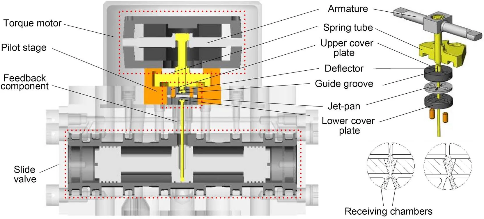
Fig. 1 Working principle of the DJSV
2.1 Working principle and flow field partition of the pilot stage
A typical pilot stage includes a jet-pan, two cover plates, and a deflector which is connected to the torque motor armature component as shown in Fig. 1. There is a V-shaped groove on the deflector. The region between the jet-pan and the cover plates forms the pilot stage's flow field, and contains a jet nozzle, a pressure outlet, and two receiving chambers. The jet nozzle and pressure outlet are connected with the oil supply port and the oil return port of the servo valve, respectively, and two receiving chambers are connected to both ends of the slide valve. When the torque motor drives the armature component to move, the deflector and guide groove deviate as well and make the fluid flow into the two receiving chambers inconsistent, resulting in different recovery pressures and driving the slide spool to move.
The flow field of the pilot stage can be divided into five regions. As shown in Fig. 2, the originis placed in the center of the jet nozzle, thedirection is the movement direction of the deflector, thedirection is the thickness direction of the jet-pan, and thedirection is the flow direction of the jet. There are five regions, as follows:
(1) Pressure jet region: the region before the jet nozzle (region before section 1-1). In this region, the fluid forms high-speed jets and the flow from the jet nozzle is driven by the pressure difference.
(2) Free jet region: the region from the jet nozzle to the area where the jet contacts the wall of the guide groove (the region between section 1-1 and section 2-2). In this region, the jet is unrestrained, freely expands and constantly mixes with the surrounding fluid. At section 2-2, the outer boundary of the jet along thedirection is 2a2, and the outer boundary of the jet along thedirection is 2b2.
(3) Mixed collision region: the region from the contact of the jet with the wall to the outlet of the guide groove (the region between section 2-2 and section 3-3). In this region, fluid collides with the wall of the deflector and causes energy loss. At section 3-3, the outer boundary of the jet along thedirection is 2bs.
(4) Secondary jet region: the region from the outlet of the guide groove to the receiving chamber (the region between section 3-3 and section 4-4), The fluid flows from the outlet of the guide groove and then expands freely again. At section 4-4, the outer boundary of the jet along thedirection is 2ar2, and the outer boundary of the jet along thedirection is 2br2.
(5) Pressure recovery region: the region where the jet enters the receiving chambers and flows out of them (the region after section 4-4). The kinetic energy of the fluid converts to pressure energy again.
2.2 Pressure jet region
In the pressure jet region, the potential energy of the fluid is converted to kinetic energy. The velocity of the jet,1, at the jet nozzle is as high as 200 m/s, which is a fully developed turbulence. The flow velocity at the jet nozzle can be calculated by the Bernoulli equation:

2.3 Free jet region based on 3D turbulent jets
Since the distance from the jet nozzle to the deflector is very short, the free jet region is in the potential core region of the 3D jet. There are two zones in the region; one is the constant velocity zone whose velocity is consistent with the jet nozzle, and the other is the shear layer whose velocity decreases gradually due to the mixing characteristics of the jet. Since the 3D jet is complex, the velocity distribution lacks effective mathematical expression. To facilitate calculation, as shown in Figs. 3a and 3b, the velocity distribution of the free jet region is simplified and assumed as follows:
1. The outer boundary of the jet along thedirection anddirection conforms to the linear expansion law.
2. The isovelocity line in the streamwise direction is rectangular and the velocity in the crossflow direction can be ignored (Marsters, 1981).
3. The velocity in the constant velocity zone is equal to the jet nozzle velocity and the velocity in the shear layer conforms to the cosine distribution (Squire and Trouncer, 1944). The shear layer boundary along thedirection is equal to the circular jet boundary with the width of jet nozzleas the diameter; the shear layer boundary along thedirection is equal to the circular jet boundary with the jet nozzle heightas the diameter.

Fig. 3 Schematic diagram of the free jet region: (a) flow field structure; (b) zones in jet section
According to the above assumptions, the inner and outer boundaries of the shear layer along thedirectiona1anda2are (Squire and Trouncer, 1944):

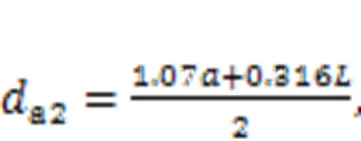
and the inner and outer boundaries of the shear layer along thedirectionb1andb2are:


whereis the length of the free jet, which is the distance from section 1-1 to section 2-2.
So the velocity distribution2in the shear layer at section 2-2 is as follows:

and in other place:

As shown in Fig. 4,and the structure parameters have the following geometric relationship:

whereis the half-angle of the V-shaped guide groove,0is the length of the free jet when the deflector is at zero position,fis the deflector displacement, and there is

whereis the thickness of the deflector,is the distance from the jet nozzle to the receiving chamber, andnis the width of the guide groove outlet.

Fig. 4 Structural parameters of the jet and the pilot stage
2.4 Mixed collision region
In this region, the jet is constrained by the guide groove, the collision between fluid flow and the guide groove results in the destruction of the 3D jet and the constant velocity zone no longer exists. Therefore, the following simplified assumptions in this region are made in combination with Fig. 5.

Fig. 5 Schematic diagram of the mixed jet region
1. The outer boundary of the jet along thedirectionbsstill conforms to the linear expansion law, but the inner boundary does not exist because the constant velocity zone disappears.
2. The velocity along thedirection at the outlet of the guide groove satisfies the cosine distribution, and the velocity distribution along thedirection is consistent.
3. The velocity in the crossflow direction is also ignored.
Based on these assumptions, the velocity distribution3at section 3-3 can be obtained as follows:


wheresis the maximum velocity at the outlet of the guide groove. This can be obtained by the momentum conservation theorem as follows:
Take two deflector walls of the guide groove (face No. 1 and face No. 2), sections 2-2 and 3-3 (face No. 3 and face No. 4) and the outer boundary of the jets (face No. 5 and face No. 6) as the control body, which is shown in Fig. 5. In the streamwise direction, from the law of conservation of momentum, the momentum difference between the flow entering and leaving the control body is equal to the momentum loss in the collision between the fluid and the two deflector walls, namely:

whereiis the momentum of the fluid entering the control body, which can be calculated by integrating the velocity at section 2-2.ois the momentum of the fluid leaving the control body.1zand2zare the momentums lost by the collision between the fluid and the two deflector walls in thedirection in unit time, respectively.
As shown in Fig. 6, triangle zones on both sides are taken as the control bodies. Thus, the momentum loss in thedirection by the collision is:


where1and2are the projected areas of the two control bodies on the plane.1and2are the flow forces acting on the two deflector walls, and1and2are the momentums entering the two triangular control bodies, respectively.

Fig. 6 Schematic diagram of the mixed jet region
2.5 Secondary jet region
In the secondary jet region, assuming that the jet boundary still conforms to the law of linear expansion as shown in Fig. 7, the inner and outer boundaries alongdirectionar1andar2and the outer boundary alongdirectionbr2of the shear layer can be obtained as follows:

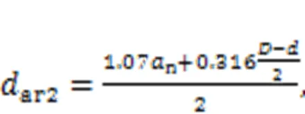
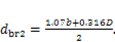
The velocity distribution4at section 4-4 is as follows:
inside the inner boundaries

outside the inner boundaries

2.6 Pressure recovery region considering jet entrainment
As shown in Fig. 7, the pressure recovery region of the pilot stage is connected to both ends of the slide valve of the DJSV. The secondary jet enters the receiving chamber and one part is converted into a flowLpushing the movement of the slide spool; the other part flows out of the receiving chamber under the effect of the pressure difference between the inside and outside of the receiving chamber.

Fig. 7 Schematic diagram of secondary jet region and pressure recovery region
For the two receiving chambers, there is


whereLis the load flow through the two chambers,1oand2oare the flow rates out of the chambers due to different pressures, and1iand2iare the flow rates into two chambers, respectively. As shown in Fig. 8, taking the right receiving chamber as an example, the fluid entering the receiving chamber consists of two parts, one is the jet flow received at section 4-42s, and the other part is the entrainment flow2tafter section 4-4. The entrainment flow is decided by the jet length because of the jet expansion; the greater the jet length, the higher the entrainment flow will be.
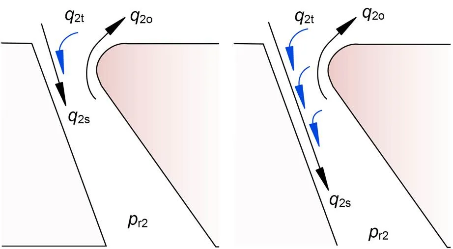
Fig. 8 Schematic diagram of jet entrainment
The jet length is related to the recovery pressure of the receiving chamber and the secondary jet flow rate; lower recovery pressure and more flow rate lead to more entrainment flow. According to the above rules, by numerical integration and the Bernoulli equation, there are


where1sand1tare jet flows received at section 4-4 and entrainment flow of the left chamber, respectivelyr1andr2are the recovery pressures of the two receiving chambers,dis the flow coefficient,Lis the load pressure difference,is the entrainment coefficient, andais the pressure constant.andacan be obtained by fitting simulation results.1iand2iare the inflow areas of the two chambers, and1oand2oare their outflow areas. According to Fig. 9, there are


where e is the width of the wedge, and Lr is the length of the receiving chamber.
According to the above model, the relationship between the pressure and the flow of the two receiving chambers under different deflector positions can be obtained.
3 Theoretical model
The static characteristics such as pressure-flow characteristics, pressure characteristics, and flow characteristics can be calculated according to the flow field model. The calculation process for static characteristics is shown in Fig. 10. First, the jet velocity at the jet nozzle is calculated by the Bernoulli equation according to the system pressure. Second, the jet velocity distribution at section 2-2 can be obtained according to the 3D turbulent jet flow law. Then, the velocity distribution at the outlet of the guide groove is calculated by the momentum theorem in the mixed collision region. After that, the velocity distribution at section 4-4 of the receiving chambers is obtained according to the secondary jet flow. Finally, according to the jet entrainment model, Bernoulli equation, and flow continuity theorem, the relationship between the load flow and the pressure difference of the two receiving chambers can be obtained. The main structural parameters of the pilot stage and the empirical constants are shown in Table 1.

Fig. 10 Calculation process of static characteristics

Table 1 Structure parameters and empirical constants
3.1 Pressure-flow characteristics
The pressure-flow characteristics refer to the relationship between the load pressure differenceLbetween the two chambers and the load flowLthrough the two chambers under different deflector positions. These are the most important static characteristics of the pilot stage. As shown in Fig. 11, it can be found that when the deflector is fixed, there is an approximate linear relationship between the load flow and the load pressure; the flow-pressure coefficient is constant. When the load pressure increases, the load flow basically decreases linearly.

Fig. 11 Pressure-flow characteristics of the pilot stage at different positions
3.2 Cut-off load pressure characteristics
When the load flow drops to zero, the load pressure differenceLbetween the two chambers is the cut-off load pressure Δ. The cut-off load pressure reflects the maximum load capacity that can be achieved by the pilot stage. It can be seen from Fig. 12 that with the increase of the deflector position, the pressure of the high-pressure chamber increases more obviously, while the pressure of the low-pressure chamber decreases and tends to be flat. The pressure difference is approximately linear with the deflector position.
3.3 No-load flow characteristics
When the load pressure decreases to zero, the load flowLis the no-load flow between the two chambers. The no-load flow reflects the response speed of the pilot stage. The higher the no-load flow is, the faster the response speed of the pilot stage is. It can be found from Fig. 12 that with the increase of the deflector position, the no-load flow increases gradually, but the flow gain gradually decreases.

Fig. 12 Pressure characteristics and flow characteristics of the pilot stage
4 Model verification and discussion
4.1 Pressure characteristics test
The pilot stage cut-off load pressure characteristics experiment of a DJSV was carried out on the test rig as shown in Fig. 13a by the Aviation Key Laboratory of Science and Technology on Aero Electromechanical System Integration, China, and the main structure parameters of the pilot stage are shown in Fig. 13b and are consistent with those in Table 1. The medium is RP3 fuel, and the temperature is 17–20 ℃. The return pressuretis zero, the supply pressuressare 1, 5, and 10 MPa, respectively. The experimental principle is shown in Fig. 14. In the experiment, different control currents Δare applied to the torque motor, the armature displacement is measured by the laser displacement sensor (LK-H025 Series, KEYENCE, Japan, with measurement resolution of 0.01 μm), and the recovery pressures of the receiving chambers are measured by a pressure gauge with measurement resolution of 0.01 MPa. To facilitate the measurement of the armature displacement, an extension board is attached to the armature. The deflector displacement can be obtained indirectly by the geometric relation of the armature components. Experimental data of deflector displacement and cut-off load pressure under different supply pressures are shown in Table 2.

Fig. 13 Experimental setup: (a) test rig; (b) jet-pan of pilot stage

Table 2 Relationship between cut-off load pressure and deflector displacement under different supply pressures
The load pressures under different supply pressures are non-dimensionalized and compared with the theoretical model results, as shown in Fig. 15. It can be found from experimental data that when the deflector displacement is small, the dimensionless pressures under different supply pressures are close to each other, while, when the deflector displacement is large, the increase of supply pressure makes the dimensionless pressure increase slightly. The model calculation also shows that there is little difference in the dimensionless pressure characteristics under different supply pressures. The model results are in good agreement with the experimental results, which indicates the reliability of the mathematical model of the pilot stage.

Fig. 14 Schematic diagram of experimental setup

Fig. 15 Dimensional cut-off load pressure characteristics
It is worth mentioning that, by modifying the parameters of the 2D mathematical model, a better fitting effect can be achieved for the static characteristics of a specific structure. However, because the flow in the third direction is ignored, the 2D model has some shortcomings in describing the flow field structure and in variable parameter analysis.
4.2 Validation of the internal flow field model
In addition to the static characteristics, the internal flow law is another important indicator reflecting the accuracy of the model. However, as the structural size of the pilot stage is too small (less than 1 mm), it is difficult to carry out a flow field visualization test, so this part is verified by finite element analysis (FEA). As shown in Fig. 16, a 3D flow field simulation model for the pilot stage of DJSV is established. In the model, a thin-walled orifice is used to simulate the load between two chambers, and orifices with different diameters can simulate the influence of different loads on the flow field. The velocity distribution of 3D jets in the free jet region and the jet entrainment in the pressure recovery region are verified in this part.

Fig. 16 Schematic diagram of the experimental setup
4.2.1Verification of the 3D jet model
The velocity distribution in the streamwise direction at section 2-2 of the deflector at 0 and 0.04 mm in the free jet region are compared based on the FEA result (Fig. 17a) and the model result (Fig. 17b). In this FEA case, the diameter of the damping orifice is zero, and the velocity distributions in the free jet area under different loads are almost the same. It can be found that the jets expand in both thedirection and thedirection. In addition, it is not difficult to find that the shape of the isovelocity line in the flow field is close to the shape of a straight slot, which is similar to the shape of the rectangular isovelocity line proposed in this study. The higher the velocity is, the more obvious is the rectangular feature of the isovelocity line. With the offset of the deflector, the range of the constant velocity region expands, and the width of the shear layer decreases. These characteristics are consistent with the 3D turbulent jet model proposed in this study.

Fig. 17 Velocity distribution along the streamwise direction at section 2-2: (a) FEA result; (b) model result
4.2.2Jet entrainment in the receiving chamber
Fig. 18 shows the velocity of the pilot stage flow field. Taking the right receiving chamber as an example, it can be seen that the jet lengths of a secondary jet entering the receiving chamber are not the same under different working conditions.
In Fig. 18a, the deflector position is 0.04 mm, the diameters of the damping orificesoare 0.5 and 0.1 mm, respectively, and the recovery pressures of the right receiving chamber are 2.74 and 9.24 MPa, respectively in the two cases. It can be found that although the deflector position is the same, the jet length is affected by the recovery pressure of the receiving chamber; the increase of pressure leads to the shortening of jet length and the reduction of entrainment flow.

Fig. 18 Jet entrainment in receiving chamber: (a) flow field under different orifices; (b) flow field under different deflector positions
Fig. 18b shows the flow field when the deflector positions are 0.04 and 0.01 mm, the diameter of the damping orificeois 0.5 mm, and the recovery pressures of the right receiving chamber are 2.74 and 2.22 MPa, respectively. It can be found that although the recovery pressure is smaller when the deflector is 0.01 mm, the jet length is still shorter due to the smaller secondary jet flow rate into the receiving chamber. Therefore, the secondary jet flow rate into the receiving chamber is another important factor related to entrainment flow rate.
In this section, some regular explorations have been made on jet entrainment in the pressure recovery region, and the parameters in Eq. (22) are obtained through parameter fitting. In fact, jet entrainment is very complex and affected by many factors, and a more accurate jet entrainment model is worth further exploration.
5 Conclusions
1. The flow law of the pilot stage of flow field of the DJSV is revealed and a new flow field mathematic model for the pilot stage of the DJSV is established based on a 3D jet model and a jet entrainment model. The process of fluid energy transfer and the working principle of the pilot stage are clarified. Compared with the traditional 2D mathematical model, the 3D mathematical model reflects the flow field structure of the pilot stage more accurately. In particular, it is advantageous in analyzing the static performance when the structural parameters change.
2. The expression of velocity distribution in a 3D free jet region is presented; the isovelocity line in the streamwise direction is rectangular. In the pressure recovery region, the coupling relationship between jets flow rate and recovery pressure is established, and the jet entrainment model is put forward to overcome the problem of low calculation of recovery pressure.
3. The pressure-flow characteristics, pressure characteristics, and flow characteristics of the pilot stage are derived. The pressure characteristics of the pilot stage are tested and the results show that the dimensionless cut-off load pressure characteristics are basically the same under different supply pressures. The experimental results are in agreement with the theoretical results. The 3D mathematical model is beneficial for the structural improvement of the pilot stage.
This work is supported by the National Natural Science Foundation of China (Nos. 51775383 and 52175059).
Jia-yang YUAN and Sheng-rong GUO designed the research. Shuang-lu LI processed the corresponding data and wrote the first draft of the manuscript. Yao-bao YIN helped to organize the manuscript and revised and edited the final version.
Shuang-lu LI, Yao-bao YIN, Jia-yang YUAN, and Sheng-rong GUO declare that they have no conflict of interest.
Karunanidhi S, Singaperumal M, 2010. Mathematical modelling and experimental characterization of a high dynamic servo valve integrated with piezoelectric actuator., 224(4): 419-435. https://doi.org/10.1243/09596518JSCE899
Li YS, 2016. Mathematical modelling and characteristics of the pilot valve applied to a jet-pipe/deflector-jet servovalve., 245:150-159. https://doi.org/10.1016/j.sna.2016.04.048
Liu XQ, Ji H, Min W, et al., 2020. Erosion behavior and influence of solid particles in hydraulic spool valve without notches., 108:104262. https://doi.org/10.1016/j.engfailanal.2019.104262
Liu YS, Dong J, Wu S, et al., 2019. Theoretical research on the dynamic characteristics of electrohydraulic servo valve (EHSV) in deep sea environment., 192:105957. https://doi.org/10.1016/j.oceaneng.2019.04.038
Marsters GF, 1981. Spanwise velocity distributions in jets from rectangular slots., 19(2):148-152. https://doi.org/10.2514/3.50935
Saha BK, Li SJ, Lv XB, 2020a. Analysis of pressure characteristics under laminar and turbulent flow states inside the pilot stage of a deflection flapper servo-valve: mathematical modeling with CFD study and experimental validation., 33(3):1107-1118. https://doi.org/10.1016/j.cja.2019.11.016
Saha BK, Peng JH, Li SJ, 2020b. Numerical and experimental investigations of cavitation phenomena inside the pilot stage of the deflector jet servo-valve., 8:64238-64249. https://doi.org/10.1109/ACCESS.2020.2984481
Sangiah DK, Plummer AR, Bowen CR, et al., 2013. A novel piezohydraulic aerospace servovalve. Part 1: design and modelling, 227(4):371-389. https://doi.org/10.1177/0959651813478288
Sforza PM, Steiger MH, Trentacoste N, 1966. Studies on three-dimensional viscous jets., 4(5):800-806. https://doi.org/10.2514/3.3549
Squire HB, Trouncer J, 1944. Round Jets in a General Stream. Aeronautical Research Council, Reports and Memoranda No. 1974, London, UK.
Stefanski F, Minorowicz B, Persson J, et al., 2017. Non-linear control of a hydraulic piezo-valve using a generalised Prandtl–Ishlinskii hysteresis model., 82:412-431. https://doi.org/10.1016/j.ymssp.2016.05.032
Tamburrano P, Plummer AR, Distaso E, et al., 2018. A review of electro-hydraulic servovalve research and development., 20(1):53-98. https://doi.org/10.13052/ijfp1439-9776.2013
Tamburrano P, Plummer AR, de Palma P, et al., 2020. A novel servovalve pilot stage actuated by a piezo-electric ring bender: a numerical and experimental analysis., 13(3):671.
Yan H, Ren YK, Yao L, et al., 2019. Analysis of the internal characteristics of a deflector jet servo valve., 32(2):31. https://doi.org/10.1186/s10033-019-0345-7
Yin YB, Yuan JY, Guo SR, 2017. Numerical study of solid particle erosion in hydraulic spool valves., 392-393:174-189. https://doi.org/10.1016/j.wear.2017.09.021
Yin YB, Li SL, Zhang XW, et al., 2019. Steady-state flow force calculation of the first stage in a deflector jet servo valve. IEEE 8th International Conference on Fluid Power and Mechatronics, p.452-458. https://doi.org/10.1109/FPM45753.2019.9035735
Zheng FX, Li S, Ding C, et al., 2021. Theoretical and experimental research on the cartridge two-dimensional (2D) electro-hydraulic servo valve., 13(2):168781402199653. https://doi.org/10.1177/1687814021996532
Zhu MZ, Zhao SD, Dong P, et al., 2018. Design and analysis of a novel double-servo direct drive rotary valve with high frequency., 32(9):4313-4323. https://doi.org/10.1007/s12206-018-0829-x
Jan. 18, 2022;
Revision accepted July 11, 2022;
Crosschecked Aug. 24, 2022
© Zhejiang University Press 2022
杂志排行
Journal of Zhejiang University-Science A(Applied Physics & Engineering)的其它文章
- Effects of bump parameters on hypersonic inlet starting performance
- Regimes of near-stoichiometric hydrogen/air combustion under reciprocating engine conditions
- Effect of droplet superficial velocity on mixing efficiency in a microchannel
- Modeling the optimal compensation capacitance of a giant magnetostrictive ultrasonic transducer with a loosely-coupled contactless power transfer system
- Hydrodynamics of high-speed robots driven by the combustion-enabled transient driving method
- Complex integrity constraint discovery:measuring trust in modern intelligent railroad systems
