Color-Changing Fabric System with Temperature Control
2022-09-29LUZhenyu卢振宇DONGAihua董爱华JIAXueru贾雪如XUEWenliang薛文良MAYanxue马颜雪
LU Zhenyu(卢振宇), DONG Aihua(董爱华), 2*, JIA Xueru(贾雪如), XUE Wenliang(薛文良), MA Yanxue(马颜雪)
1 College of Information Science and Technology, Donghua University, Shanghai 201620, China
2 Engineering Research Center of Digitized Textile & Fashion Technology, Ministry of Education, Donghua University, Shanghai 201620, China
3 College of Textiles, Donghua University, Shanghai 201620, China
Abstract: Color-changing fabric system with temperature control is designed through textile design and electronic technology. The system inserts a conductive fabric inside a fabric coated with thermochromic powder. A temperature control system is constructed to adjust the current to raise the temperature of conductive fabric to the active point of thermochromic powder and keep the temperature in stable. Therefore, the fabric could sense the temperature and change colors. In order to achieve wearability, mobile power supply is selected and flexible sensor is adopted. Kalman filter is engaged in the proportion integration differentiation (PID) control algorithm to reduce the interference of measurement noise. The experiment result shows that the proposed color-changing fabric system could reach the target temperature quickly and meet the design demands for color-changing.
Key words: conductive fabric; temperature control; wearability; Kalman filter
Introduction
With the improvement of living standards, consumers are pursuing higher levels of fabric beauty. Intelligent color-changing fabrics are designed from stage performances to fever predicting and environment temperature change predicting,etc.[1]. The color-changing fabric has become a common concern of researchers and companies at home and abroad[2]. For example, the technical staff launched a clothing that can change color with the mood of the wearer[3]. Sa-ran fabric is made of a special temperature-sensitive microcapsule, which makes the fabric transparent upon heating and becomes a temperature-sensitive color-changing fabric[4]. Wuetal.[5]developed new material named “photothermal sensitive crystals” to dye and print on fabric, so the fabric could sense the environmental temperature and change the color.
The above color-changing fabric or color-changing materials just perceive environmental temperature and then change colors consequently. Changing fabric color by actively controlling the temperature of fabric is to be explored. Researches on temperature control system for color-changing fabric are mostly in the laboratory stage. Aspects on safety, wearable performance and electronic technology should be combined in the product design[6-7].
Color-changing fabric system with the temperature control is developed by combining textile design and information technology. The textile material and conductive copper wire are mixed into the conductive fabric and embedded into the fabric. Then the mixed slurry of thermochromic powder is printed on fabric by a screen printing process. The insulation layer is added to make the temperature of the fabric approximate to that of the conductive fabric. In addition, the control algorithm is designed according to the temperature characteristic of conductive fabric, and a flexible sensor is used to collect the temperature data of the fabric. Kalman filter is applied in the control algorithm to reduce the interference of measurement noise. The temperature controller is designed to adjust the output current to heat the conductive fabric, so that the fabric temperature can reach the active point temperature of the thermochromic powder and keep it in stable. The experiment result shows that the proposed color-changing fabric system can meet the design demands for color-changing.
1 Structure of Color-Changing Fabric System with Temperature Control
Color-changing fabric system with temperature control designed in this paper is mainly composed of color-changing fabric (thermochromic fabric, conductive fabric, and insulation layer) and temperature controller system (temperature controller, power module and flexible sensor), as shown in Fig. 1.

Fig. 1 Structure of color-changing fabric system with temperature control
In this system, the temperatureTcontroller outputs the currentIto heat the conductive fabric, and the conductive fabric transfers the heatQto the thermochromic fabric. The thermochromic fabric is printed on the fabric by the mixed slurry of thermochromic powder through a screen printing process, and the sponge is added as an insulation layer, so that theTof the fabric is the temperature of the conductive fabric approximately. The deviation between the temperature of the color-changing fabric collected by the flexible sensor, and the temperature setting is transmitted to the temperature controller, which adjusts the output current to make the fabric reach the active point temperature of the thermochromic powder and keep it in stable. Therefore, the thermochromic fabric can change colors. In addition, a power module is designed to provide energy for the system.
2 Color-Changing Fabric Design
2.1 Color-changing fabric structure
The color-changing fabric is composed of thermochromic fabric, conductive fabric and insulation layer. They are closely bonded by cloth adhesive, as shown in Fig. 2.

Fig. 2 Structure of color-changing fabric
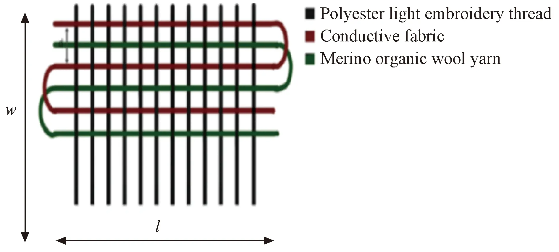
Fig. 3 Structure of conductive fabric
For thermochromic fabric, the mixed slurry of the thermochromic powder is printed on the silk fabric by a screen printing process, and the fabric changes color at the temperature active point of thermochromic powder. The temperature and color change of common thermochromic materials are shown in Table 1. The conductive fabric transfers the heat to the thermochromic fabric. The sponge is added as an insulation layer, so that the temperature of the thermochromic fabric is approximately the temperature of the conductive fabric.
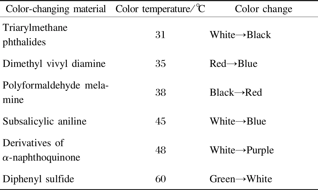
Table 1 Common thermochromic materials
2.2 Conductive fabric design
The design of conductive fabric is to determine the fabric size, material, and structure.
In this paper, the size of conductive fabric in plain woven is 10 cm×10 cm. It equals to the size of color-changing area. The conductive fabric material is selected based on the thermal conductivity and conductive stability. The warp yarn is 13.3 tex×2 polyester light embroidery thread. The weft yarn is composed of conductive part and non-conductive part. Among them, the conductive part adopts a single conductive copper wire with a cross-section diameter of 0.1 mm (insulation). Compared with iron wire and silver wire, the temperature coefficient of resistance (TCR) of copper wire within 0-50 ℃ is smaller. According to Eq. (1), the resistance of copper wire varies little with temperature, so the conductive stability is better.
R1=R0[1+α(T-T0)],
(1)
whereR1is the resistance inT,R0is the resistance inT0, andαis TCR.
In order to improve the insulation effect, the non-conductive part of the weft yarn is 100% ultra-fine Merino organic wool yarn with a fineness of 1/50 nm. The weaving method is to weave a conductive copper wire and a wool yarn alternately as weft yarn. Figure 3 shows the structure of conductive fabric, wherelis the fabric width, andwis the fabric length.
For the sake of making the conductive fabric reach the target temperature quickly, the structure of the conductive fabric is designed to maximize the heat dissipation power in unit area of the conductive fabric.
The equation of heat dissipation power per unit area of fabric is shown as
(2)
whereP′ is the heating power per unit area,dis spacing of conductive copper wires,Sis the area of conductive fabric,Ris the resistance of conductive copper wire,cis the number of copper wire shares, andηis the resistance per unit length of copper wire.
The area equation of conductive fabric is shown as
S=l×w.
(3)
The equation of resistance of conductive copper wire is shown as
(4)
wheremis the length of the conductive copper wire.
The bending region of conductive copper wire is approximately a semicircle. The equation of length of conductive copper wire is shown as
(5)
wherelandware determined by the size of the fabric color-changing area, andηis determined by the copper wire. In this paper,l=10 cm,w=10 cm,η= 0.020 7 Ω/m. In order to meet the requirement of system rapidity, the smallercanddare, the largerP′ is. Therefore,ctakes the minimum value 1.dis determined by the distance between copper wires, that is, the diameter of wool yarn. Due to process limitations,dis taken as 0.08 mm. At this time, the heat dissipation of conductive fabric is more uniform.
3 Temperature Control System Design
The design of temperature control system includes controller scheme design and controller parameter design. The controller scheme design includes the structure design of color-changing fabric system with temperature control, the selection of sensor, and the design of power module. The controller parameter design is based on the acquired temperature characteristics of conductive fabric to design the control algorithm and parameters, so that the conductive fabric can reach the target temperature, and at the same time ensure the system rapidity, stability, and anti-interference.
3.1 Controller scheme design
Color-changing fabric temperature controller are composed of TI company’s MSP430fr2355 (MSP430) chip and TPS92602-Q1 booster controller, USA. The peripheral devices mainly include TMP117 MAIDRVT (TMP117, USA) sensor and power module. The structure of color-changing fabric temperature controller is shown in Fig. 4.
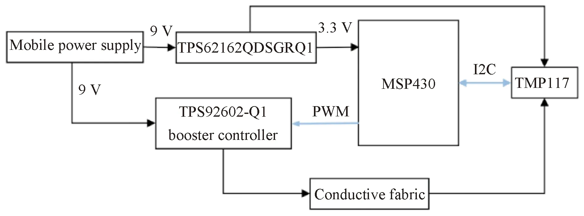
Fig. 4 Structure of color-changing fabric temperature controller
(1) MSP430 sends pulse width modulation (PWM) wave with adjustable duty ratio to control the output voltage of TPS92602-Q1 booster controller. As the size of conductive fabric and the distance between copper wires are determined, the resistance of conductive fabric is determined. The booster controller achieves the purpose of heating conductive fabric by adjusting the current flowing through the conductive fabric.
(2) The power module is composed of 9 V mobile power supply and TPS62162QDSGRQ1 buck chip. The output voltage of the mobile power supply is step-down to 3.3 V through TPS62162QDSGRQ1 chip, which supplies power to MSP430 microcontroller and TMP117. The mobile power supply also directly supplies 9 V power to TPS92602-Q1 booster controller. In this paper, the working current of the system in stable state is 800 mA the endurance of 6 h. The mobile lithium battery pack is selected with the capacity of 4 800 mA·h.
(3) The TMP117 sensor provides the output of the bipolar junction transistor (BJT) silicon band gap temperature sensor to the 16-bit analog-to-digital converter (ADC), and transmits the temperature data of the conductive fabric to the microcontroller in real time by the I2C serial interface. Compared with the thermal resistance sensor, the TMP117 sensor improves the measurement accuracy by 0.08%. Compared with thermocouple sensor, the complex signal conditioning circuit is omitted.
To ensure the wearability of the proposed color-changing fabric system with temperature control, flexible printed circuit board(PCB) is selected to make the flexible sensor in long strips and cover the distance between the temperature controller and the conductive fabric. The main materials of the flexible PCB board for sensor are copper wire, solder resistance film, and FR4,etc.[8]The size of PCB board is 15 cm×0.8 cm, as shown in Fig. 5(a). In addition, the size of PCB board for temperature controller in this paper is 5.5 cm×4.5 cm as shown in Fig. 5(b).
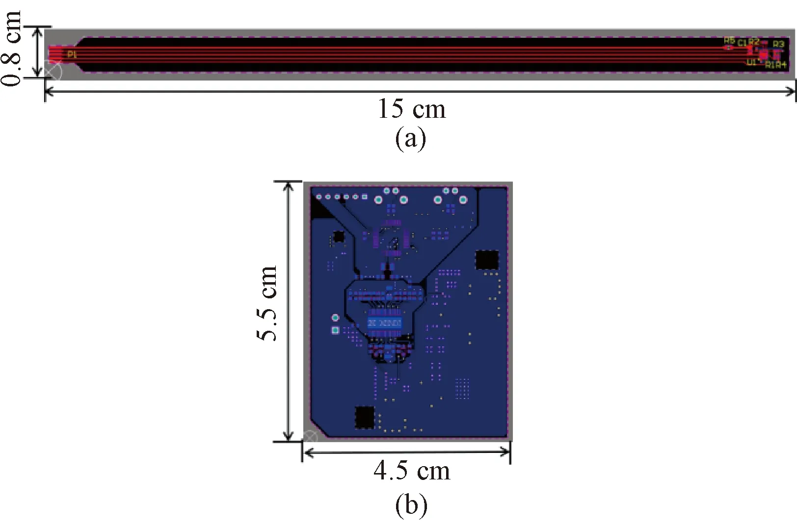
Fig. 5 PCB of (a) flexible sensor; (b) temperature controller
3.2 Controller parameter design
The controller parameter design include the design of proportion integration differentiation (PID) controller, the design of Kalman filter, and the temperature control curve of the conductive fabric.
3.2.1DesignofPIDcontroller
The PID controller is designed based on the temperature characteristics of the conductive fabric. According to the temperature characteristic of conductive fabric, the object can be identified as a first-order lag link, and the object transfer function can be obtained by using the two-point method in test modeling method[9-10], which is shown as
(6)
Incremental PID controller is adopted and Eq.(7) shows the PID controller.
uk=uk-1+KP(ek-ek-1)+KIek+KD(ek-2ek-1+ek-2),
(7)
whereKPis the proportional parameter;KIis the integral parameter;KDis the differential parameter;ekis the current error;ek-1is the error of the last moment;ek-2is the error of the previous moment;ukis the PWM output value.
3.2.2DesignofKalmanfilter
The proposed temperature control system is interfered by measurement noise during the control process mainly due to the gap between the conductive fabric and the flexible sensor. When the true value of conductive fabric is 25.0 ℃, the deviation between the measured value and the true value of the flexible sensor is shown in Fig. 6. The maximum deviation is 0.80 ℃, and the average deviation is 0.32 ℃.
Kalman filter is therefore engaged into the PID control algorithms to reduce the interference of measurement noise. The system combines Kalman filter with traditional PID control, whose structure diagram is shown in Fig. 7. This control method integratese(k)(the deviation ofr(k) andXk|k), control quantityu(k) and system outputz(k) through Kalman filter, which reduces the interference of control interferenceWand measurement interferenceVon output, and improves the performance of the system eventually[11-12].
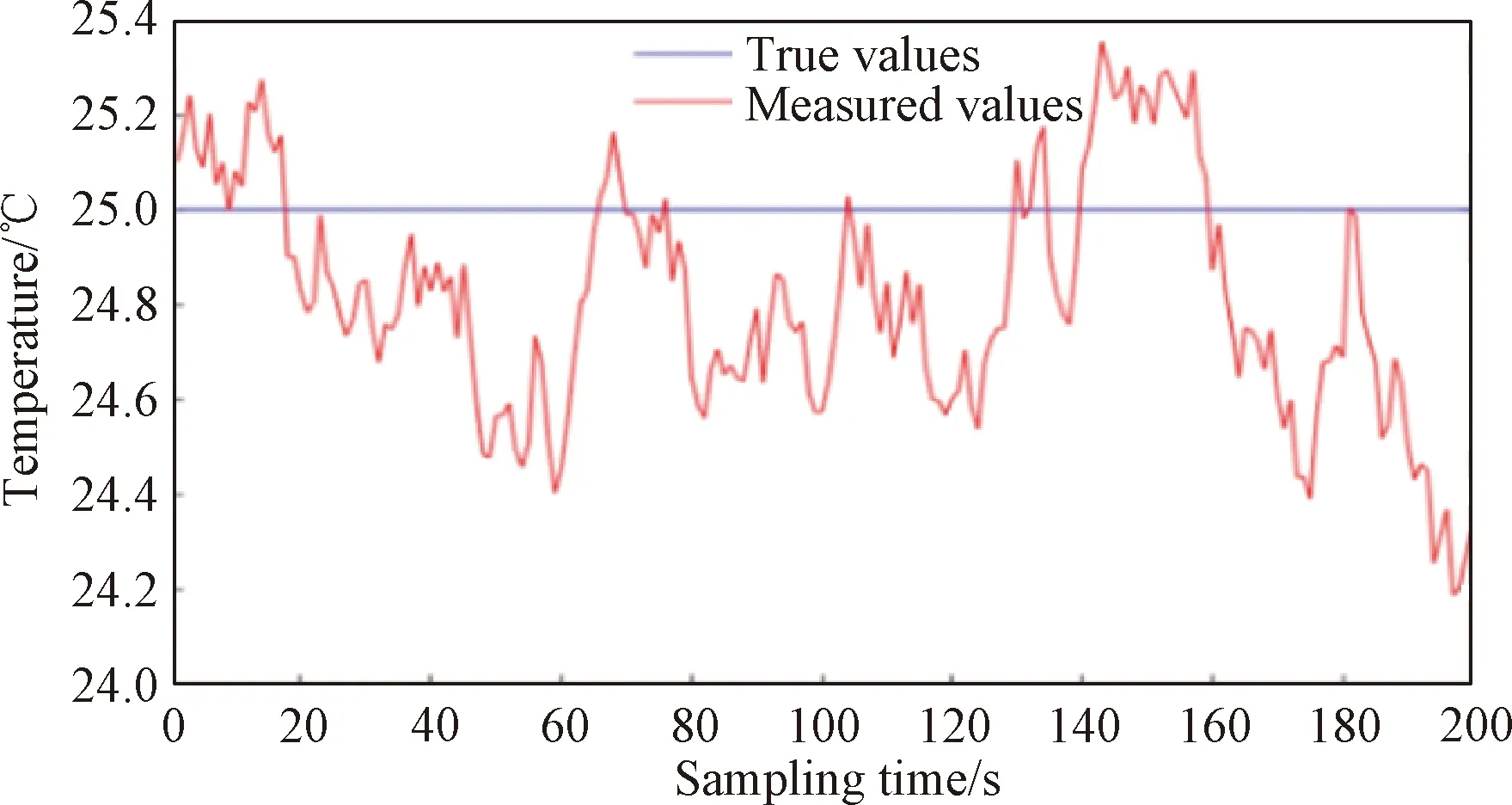
Fig. 6 Deviation between true values and measured values of flexible sensor
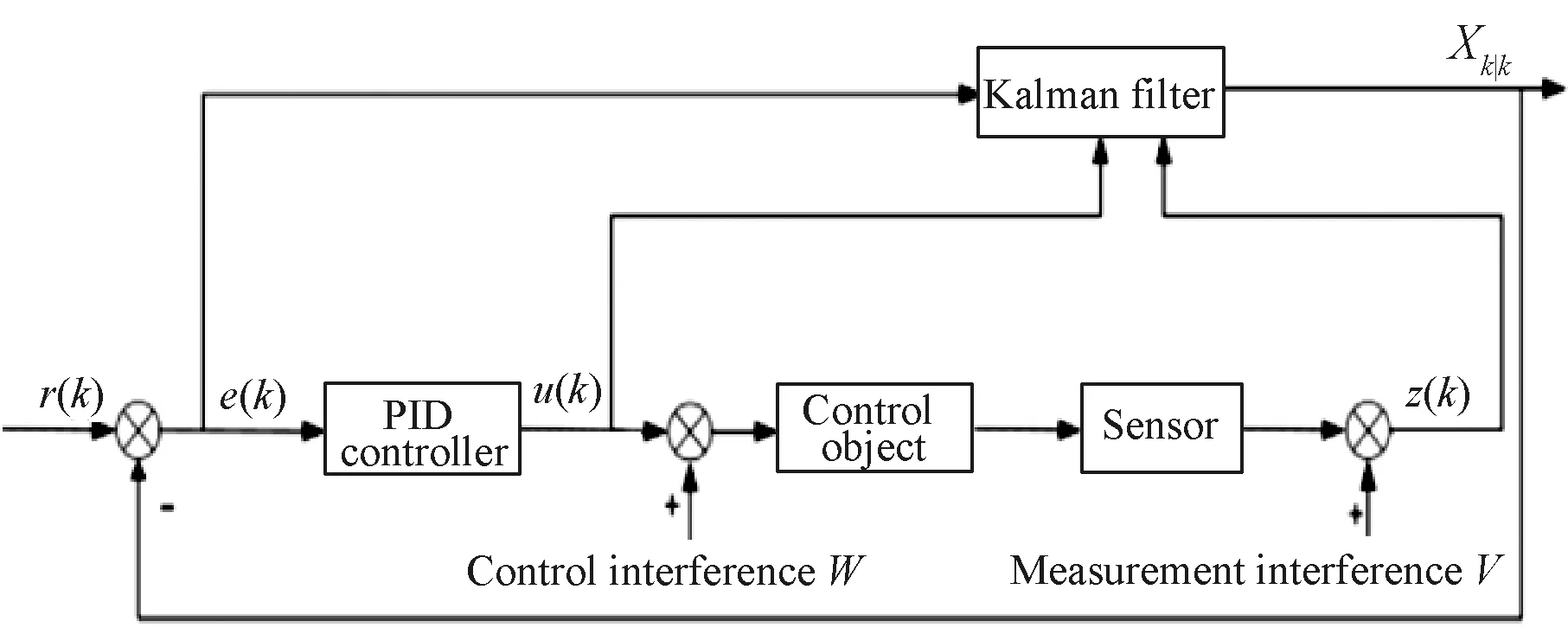
Fig. 7 Structure of Kalman filter-based PID control system
Kalman filter is an algorithm for optimal estimation of system state by using linear system state equation and system input and output observation data[13-15], mainly composed of prediction equation and update equation.
Prediction equations and update equations are listed in Eqs.(8)-(11), respectively.
Xk|k-1=FkXk-1|k-1+Bkuk,
(8)
(9)
(10)
Xk|k=Xk|k-1+Kk(zk-HkXk|k-1),
(11)
Pk|k=(I-KkHk)Pk|k-1,
(12)
whereXk|k-1is the prediction of current moment at momentk-1;Xk-1|k-1is the optimal value at timek-1;Fkis the transformation matrix in the state ofXk-1|k-1;Qkis the covariance of system process noise;Rkis the covariance of measured noise;Pk|k-1is the system covariance matrix at timek;Kkis the Kalman gain;Hkis the object prediction matrix;zkis the value measured by the sensor;Xk|kis the optimal estimation value at timek.
The state of the system is one-dimensional andFkandHkis set to 1. The result value of predicting the current moment at timek-1 is the optimal value at timek-1. Considering the system is greatly disturbed by measurement noise,RkandQkare set as 0.543 and 0.001, respectively.
3.2.3Temperaturecontrolcurveofconductivefabric
The control process includes manual mode and automatic mode. The manual mode is engaged at the initial stage when the fabric temperature is far less than the set value. A constant current of 1.2 A is set as the output current in manual mode and the conductive fabric is continuously heated to make its temperature close to the target temperature quickly to achieve preheating effect. After that, manual mode is transferred to automatic mode and the PID algorithms work to heat smoothly and avoid overshooting effectively for the temperature of conductive fabric.
The manual mode and the automatic control mode with PID control are shown in Fig. 8(a). Between 0 and 230 s, the manual control is used to make the conductive fabric temperature quickly reach 45 ℃. After 230 s, the automatic control is adopted. The conductive fabric can meet the temperature control requirements and be stable at 48 ℃. The fabric changes color stably at 480 s, and the adjustment time is 250 s.
The PID temperature control procedure with Kalman filter is showed in Fig. 8(b). The fabric changes color steadily in 330 s, and the adjustment time is 100 s. Compared with Fig. 8(a), the adjustment time and the overshoot in the modified system with Kalman filter are decreased by 150 s and 16.7%.

Fig. 8 Temperature control with (a) PID; (b) Kalman filter-based PID
The anti-interference performance test of system is showed in Fig. 9. When the system runs to 480 s, it is in a stable state. At this point, an interference is added to the system, and the system returns to the stable state at 690 s. The time for overcoming interference is 210 s, which proves that the system has good anti-interference ability.

Fig. 9 Anti-interference performance test of system

Fig. 10 Effect of thermochromic powder at 48 ℃ on color-changing fabric by adding the temperature control system: (a) before; (b)after

Fig. 11 Effect of thermochromic powder at 48 ℃ on color-changing pillows by adding the color-changing fabric system with temperature control: (a) before; (b) after
4 Effect Display of Color-Changing Pillows
In order to verify performance of the color-changing fabric system with temperature control in the actual process, the thermochromic powder of 31, 38, and 48 ℃ in Table 1 are used to make color-changing pillows.
Firstly, the effect of thermochromic powder at 48 ℃ on color-changing fabric before and after adding the temperature control system are showed in Figs. 10(a) and 10(b). And the color-changing fabric system with temperature control is applied to pillows. The pillow turned from white to blue. The comparison of the effect of color-changing pillows before and after adding the color-changing fabric system with temperature control are shown in Figs. 11(a) and 11(b).
Besides, 31 ℃ thermochromic powder is selected. The temperature control curve of the color-changing fabric is shown in Fig. 12. When the system runs to 178 s, the system enters the automatic control stage, and the fabric stably changes color in 330 s. During the control process, the highest temperature of color-changing fabric is 31.6 ℃, and it stabilizes at 31.08 ℃. Therefore, the regulation time of the system is 152 s and the overshoot is 1.524%.
The comparison of the effect of color-changing pillows before and after adding the color-changing fabric system with temperature control are shown in Figs. 13(a) and 13(b). The pillow turned from white to black.
Finally, the thermochromic powder of 38 ℃ is selected, and the corresponding temperature control curve of color-changing fabric is shown in Fig. 14. When the system runs to 162 s, the system enters the automatic control stage, and the fabric changes color stably at 310 s. During the control process, the highest temperature of color-changing fabric is 38.50 ℃, and it stabilizes at 37.09 ℃. Therefore, the regulation time of the system is 148 s and the overshoot is 1.724%.

Fig. 12 Temperature control curve of fabric with 31 ℃ thermochromic powder
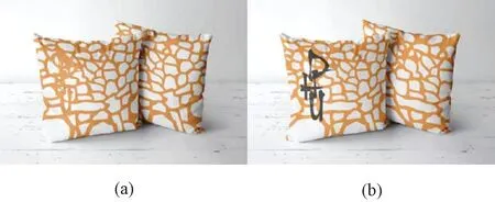
Fig. 13 Effect of thermochromic powder at 31 ℃ on color-changing pillows by adding the color-changing fabric system with temperature control: (a) before; (b) after
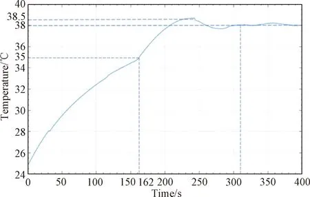
Fig. 14 Temperature control curve of fabric with 38 ℃ thermochromic powder
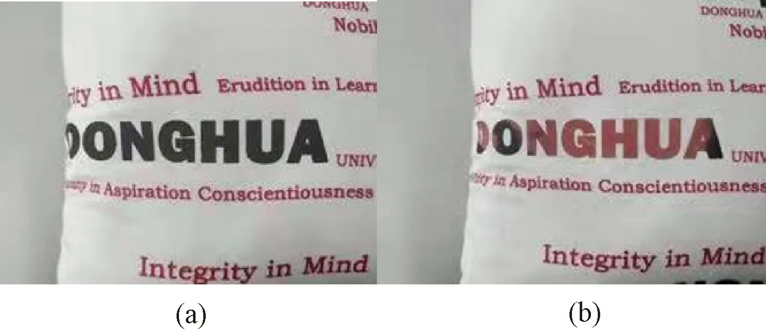
Fig. 15 Effect of thermochromic powder at 38 ℃ on color-changing pillows by adding the color-changing fabric system with temperature control: (a) before; (b) after
Only part of the “DONGHUA” pattern has thermochromic powder. The comparison of the effect of color-changing pillows before and after adding the color-changing fabric system with temperature control are showed in Figs. 15(a) and 15(b). The pillow turned from black to red.
In the experiment on the color-changing pillows made of 31, 38, and 48 ℃ thermochromic powder, it was proved that the system showed good control performance and color-changing.
5 Conclusions
The conductive fabric is embedded in the fabric (containing thermochromic powder), and the temperature controller is designed to adjust the output current to heat the conductive fabric, so as to actively control the temperature of the color-changing fabric to change the color. At present, the color-changing fabric system with temperature control is still in the laboratory stage, and many aspects need to be optimized. In the future work, the optimization of the system has the following aspects: the heat dissipation model is optimized to be sensible; the volume and mass of the system are further optimized to make it wearable; the control algorithm and control parameters are optimized to reduce the influence of ambient temperature on temperature control; the accuracy of the algorithm is improved by reducing error in sensor measurement.
猜你喜欢
杂志排行
Journal of Donghua University(English Edition)的其它文章
- Classification of Preparation Methods and Wearability of Smart Textiles
- Computer-Based Estimation of Spine Loading during Self-Contained Breathing Apparatus Carriage
- Click-Through Rate Prediction Network Based on User Behavior Sequences and Feature Interactions
- Predictive Model of Live Shopping Interest Degree Based on Eye Movement Characteristics and Deep Factorization Machine
- Object Grasping Detection Based on Residual Convolutional Neural Network
- Time Delay Identification in Dynamical Systems Based on Interpretable Machine Learning