Investigation on the performance of a helico-axial multiphase pump under slug flow
2022-09-23JiXingZhngJinZhngYeZhouZiYiYiChengGungCo
Ji-Xing Zhng , Jin-Y Zhng , Ye Zhou , Zi-Yi-Yi Cheng , Gung-D Co
a College of Mechanical and Transportation Engineering, China University of Petroleum, Beijing,102249, China
b Beijing Key Laboratory of Process Fluid Filtration and Separation, China University of Petroleum, Beijing,102249, China
c China Institute of Water Resources and Hydropower Research, Beijing,100044, China
Keywords:Multiphase pump Slug flow Gas void fraction (GVF)Hydraulic performance Fluid-structure interaction
ABSTRACT The helico-axial multiphase pump is often used for gas-liquid mixture transportation in offshore oilfields, and slug flow is the main reason for the unstable operation of the pump. Aimed for slug flow condition, a self-designed three-stage multiphase pump is set to the object to perform unsteady simulations and fluid-structure interaction calculations,and the inlet gas void fraction (IGVF) is set from 20%to 80%.The results show that affected by the flow from the slug,the gas-liquid two-phase flow pattern in the multiphase pump changes sharply, resulting in severe fluctuations in the differential pressure,spindle torque and deformation of the multiphase pump. The gas-phase enters the first-impeller along the suction blade surface when affected by Taylor bubbles, while the second and third-stage impellers gas-phases are in the form of small air masses flow into the impeller along the pressure blade surface.The deformation trend of impeller torque, differential pressure and the main pump spindle is similar to that of trigonometric function,while the fluctuation of torque is more intense,and the shape variable of spindle increases with the inflow of liquid plug, and the maximum deformation amount increases by 10.9% at high GVF relative to IGVF.
1. Introduction
With diminishing onshore oil resources and increasing international energy demands, it is imperative to increase the development of offshore oil.The output of oil wells is mainly a mixture of oil, gas and water, and also contains a small amount of sand.Traditional transportation means requires to separate and then transport the output, which is difficult to maintain and has high mining cost. Therefore, it is particularly important to reduce the equipment for underwater production systems and offshore platforms.The use of the multiphase pump to transport the mixture of oil, gas and water to land or offshore main platforms before separation treatment is the preferred process for the development of offshore oil and gas field.
The helico-axial multiphase pump is compact in structure and large in displacement, it can still operate safely when the fluid contains a small part of solid particles (Saadawi, 2007). So far, the helico-axial multiphase pump has been used successfully in deep sea, desert, and marginal oilfields (Shippen and Scott, 2002). At present, the researches of the helico-axial multiphase pump involve various aspects such as hydraulic design, optimization methods, numerical simulation, hydraulic performance and internal flow field visualization experiments.

Nomenclature Abbreviations GVF gas void fraction IGVF inlet gas void fraction const constant SST shear stress transport [-]Symbols M interphase force, N fn mass force, N u fluid velocity, m/s t time, s p Pressure,pa Q fluid volume, m3 C coefficient rg average bubble radius, m dg characteristic length, m Re Reynolds number k turbulent kinetic energy, m2/s2 a relative acceleration Greek letters ω specific dissipation rate,1/s ε turbulence dissipation rate,m2/s3 μ dynamic viscosity, Pa∙s ρ density, kg/m3 α volume fraction Subscripts n a certain phase l liquid phase g gas phase 0 initial state D drag force A additional mass force
In terms of the hydraulic optimization design, Cao et al. (2005)used iteration design of direct and inverse problems to design the geometric structure of the helical-axial multiphase pump impeller.The design and calculation process of the multiphase pump impeller were proposed. Kim et al. (2015) screened out the operating parameters which have great influence on the performance of the multiphase pump by orthogonal design method. Furthermore,they optimized the diffuser based on response surface method and numerical simulation method. Liu et al. (2018a, 2019a) carried out the optimization design of inlet and outlet blade angle of the impeller and other parameters based on orthogonal design method. The design of inlet blade angle of the three-stage multiphase pump was optimized by predicting the performance of the multiphase pump based on oseen vortex model. So that the head and efficiency of the pump were increased by 0.29% and 0.19%respectively.Han et al.(2020)studied the impact of airfoil thickness variation on the performance of the helico-axial multiphase pump,and optimized the airfoil thickness ratio coefficient to get higher efficiency.Suh et al.(2017a)optimized the impeller and diffuser to improve its efficiency based on response surface method. Zhang et al. (2014) proposed a 3D blade hydraulic design method for the helico-axial impeller. Considering the compressibility of the gas.Zhang et al. (2018a) proposed the hydraulic design method of the stepped impeller.In addition,Zhang et al.(2011,2017)proposed the optimization design methods for the impeller based on neural network, genetic algorithm and boundary flux diagnosis method.
In terms of numerical simulations,Yu et al.(2014,2015)studied the magnitude of four main forces which contain drag, lift, virtual mass and turbulent dispersion forces of the helico-axial multiphase pump in different conditions of GVF, bubble diameter and rotational speed. The influence of four main forces on the predicted performance of the multiphase pump were investigated. Furthermore, they analyzed the effect of virtual mass force on the trajectories of bubbles in the blade area and differential pressure of the multiphase pump according to various GVFs at unsteady state.Zhang et al. (2018b) conducted a numerical simulation of a multiphase pump in full passages. The results revealed the relationship between the position of the short guide vane and hydraulic performance of the pump, which provided theoretical support for optimization design of the multiphase pump diffuser. Liu et al.(2018b, 2019b) investigated gas-liquid two-phase flow characteristics of the multiphase pumps under inlet GVFs of 10%and 20%to confirm mechanism of gas pocket formation by used dynamic mode decomposition. They investigated the effect of various interphase forces acting between the liquid and gas of the internal flow field in the pump. The results provided references for the setting of the interphase forces in the numerical simulation. Suh et al. (2017b) developed the Euler-Euler multiphase flow model for numerical simulation of the flow field of multiphase pump,and studied the hydraulic performance of the multiphase pump under different phase forces, turbulent dissipation forces and bubble diameters.Zhang et al.(2019b)produced an inhomogeneous bubble model, which was used to predict the hydraulic performance, by considered the effects of bubble aggregation and breakage in the multiphase pump. Li et al. (2019) carried out a numerical simulation of gas-liquid two-phase distribution in the multiphase pump based on bubble number density equation,and investigated the effects of bubble polymerization and collapse on the two-phase flow pattern.
In the field flow visualization experiment, Falcimaigne et al.(2002) investigated the internal flow field of a single-stage helico-axial multiphase pump by use LDA (Laser Doppler Anemometer)and high-speed photography technology. The flow fields at 6 sections from the entrance of the impeller to the outlet of the diffuser at different rotational speeds and flow rates were obtained.The influences of Reynold’s number on the flow characteristics were analyzed, and the bubble diameter distributions for bubbly flow of the impeller were obtained. Serena and Bakken (2015a,b)designed an experimental platform for visualization and unsteady-state analysis of multiphase pumps, visualization experiments and dynamic measurements deviated from design working conditions using a mixture of water and air as working fluid were carried out. Zhang et al. (2015, 2016) conducted visualization experiment for the inlet flow field of a three-stage multiphase pump to investigate the flow characteristics at the entrance and the three stage impellers of the multiphase pump.The gas-liquid twophase flow pattern and bubble diameter distributions according to different GVFs were obtained. The results also revealed the mechanism of gas pocket in the impeller.
In addition, the researchers also carried out investigations on the pressure pulsations,cavitation,radial force and other problems of the helico-axial multiphase pump. Zhang et al. (2018c) performed the numerical simulation to investigate the influence and mechanism of the inlet GVF on the hydraulic performance and pressure pulsations of multiphase pump. Liu et al. (2018c) to investigate the transient flow and dynamic characteristics of the caviting flow on the multiphase pump based on the multiphase flow mixture model and full cavitation model. The effect of unsteady excitation induced by cavitation on the variation of radial force was explored,which provided supports for understanding the unsteady characteristics of multiphase pump. Zhang et al. (2019c)studied the pressure pulsations characteristics of multiphase pump through numerical simulation, exploring the causes and influencing factors of pressure pulsations. Xu et al. (2019) made effort on the characteristics of pressure pulsations in the multiphase pump and the influence of flow patterns on pressure pulsations. Zhang et al. (2019a) determined the effect of different tip c1earance on the performance, flow field characteristics and pressure pulsations of the multiphase pump.
Up to now, most of the studies on the helico-axial multiphase pump have been directed to the working conditions of steady flow at the inlet, and there are few studies on slug flow conditions.However, slug flow and sudden changes of GVF may occur in the production of the oil field,which could lead to extremely unstable operating, such as mechanical failure in severe cases. Hua et al.(2012) performed an experimental investigation of the multiphase pump under slug flow. The rotational speed of the multiphase pump was kept unchanged,while the flow rate of liquid and gas in the inlet pipeline changed periodically with a period of about 75 s.The outlet pressure remained basically unchanged due to the pressure adjusting device installed on the outlet of pump, and the inlet pressure changed violently with various GVFs. The drastic change in the pressure difference between the inlet and outlet determined a large pulse-like change induced by torque,which led to unstable operating of the pump system.A buffer tank(Saadawi,2008) (also called homogenizer) is usually installed at front of the multiphase pump to avoid inlet GVF fluctuates, with a certain amount of the liquid stored at the bottom of the tank. When the inlet GVF is high, the stored liquid would mix with the inlet working fluid to reduce the GVF at the entrance of the pump.However,this device can only serve as a buffer for a short period.If the slug flow lasts for a long time, the liquid inside the buffer homogenizer will also be exhausted. And then the device cannot stabilize the operating, or reduce the inlet GVF of the multiphase pump.In this case,the oil well production with a changing GVF will enter the multiphase pump in real time, making the multiphase pump working in unsteady state with frequent switching between high and low GVFs.The result is that the load of the pump and the torque of the shaft change frequently and drastically, which might cause a mechanical failure. This is one of the bottlenecks faced by the helico-axial multiphase pump in the oil and gas transportation process, which makes it urgent to optimize the operation stability of the multiphase pump.
At the same time, the helico-axial multiphase pump is often applied in offshore oilfield underwater production systems, in variable wave loads and complex marine environments. Once it fails, it will cause huge economic loss and serious environmental pollution,and the abrupt change of GVF and slug flow condition are the main reasons for the unstable operation of multiphase pump.The particularity of the“deep sea”application puts forward higher requirements on stability and reliability of the helico-axial multiphase pump.
Aiming at the problem of slug flow in the helico-axial multiphase pump, which affects its operation stability, the paper takes the self-designed three-stage helico-axial multiphase pump as the research object. A slug flow with a high and low GVF interval was set as inlet condition,and unsteady numerical simulations and the deformation of the main pump fluid-structure interaction calculation were applied to investigate the internal flow characteristics of the multiphase pump. The variation of gas-liquid flow pattern,differential pressure of the impeller,torque as well as deformation of the shaft in the gas-liquid two-phase flow of the pump were studied, to reveal the instability mechanism of the helico-axial multiphase pump working under slug flow.
2. Research model and mesh
2.1. Research model
The research model in this paper is composed of three compression cells,the import extension and the exit extension,and according to the theory of piecewise incompressibility, the structures of these three-stage compression cells is same. The length of the import extension was set to one time as the axial height of the compression cell,and the length of the exit extension was set to three times as the axial height of the compression cell,as shown in Fig.1 for the three-stage helico-axial multiphase pump geometric model.The diameter of the impeller shroud is 0.1344 m,the half cone angle of the hub is 5°and the diameter of the hub inlet is 0.133 m. The impeller blade wrap angle is large, which can suppress gas-liquid two-phase separation inside the impeller partly.The number of impeller blade is 3 and the number of guide vanes is 10. There is blade tip c1earance of 2% times of the blade height in the pump near the shroud. Fig. 2 and Fig. 3 respectively show the impeller and diffuser geometric models of the multiphase pump.
2.2. Mesh
Structure mesh was adapted for the dispersion of flow field.The topology optimization based on adaptive mesh was used to divide the topology structure of the geometry. More information about impeller and diffuser is given in this paper, such as the orthogonality quality、mesh expansion factor,aspect ratio,TGrid skew and the y + value, were calculated and analyzed, as shown in Table 1,and Grids of the impeller and diffuser are shown in Fig.4 and Fig.5 respectively.The differential pressure curve of multiphase pump at different grid numbers is shown in Fig.6,The influence of the grid number of the impeller on the total differential pressure of the pump is investigated to verify the independence of the grid.It can be seen from the figure that when the number of grids reaches 2.4×10⁶,the total differential pressure changes little with the grid number.In order to account the requirements of calculation speed and accuracy,the number of impeller grids in the calculation model was set to 278976, and the number of diffuser grids was set to 247240.
3. Numerical calculation model and boundary condition setting
3.1. Numerical calculation model
The mixture of water and air was selected as the working fluid.The Particle model based on Eulerian-Eulerian method in ANSYS CFX software was applied in the two-phase flow model. In this model,water was set to continuous phase and gas was regarded as dispersed phase. The interaction force between the two phases were calculated on the basis of the slip coefficient between the phases, the physical properties of the continuous phase, and the area of the interphase between two phases. When calculating the flow field of the helico-axial multiphase pump, there were some assumptions:
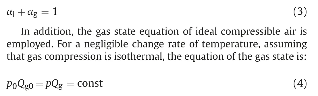
(1) The liquid phase of the mixture medium was considered as an incompressible fluid and the gas phase was considered as an ideal compressible fluid.
(2) The exchange of heat and mass between the gas and liquid phases and between the system and outside world was not considered. No chemical reaction took place inside the flow field.
(3) The entire thermodynamic process was treated as an isothermal process.
3.1.1. Governing equation
Based on the above assumptions,the basic controlling equations of the flow field in multiphase pump can be described by the following formulations:

Fig.1. Schematic diagram of the research model.
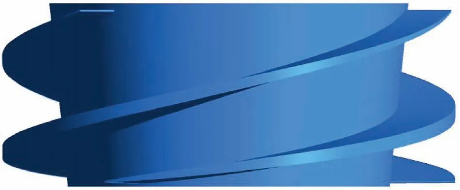
Fig. 2. Schematic diagram of the impeller model.
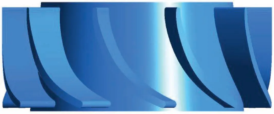
Fig. 3. Schematic diagram of the diffuser model.

Table 1 Mesh quality information for the impeller and diffuser.
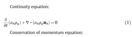
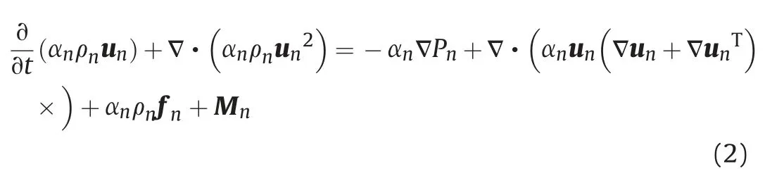
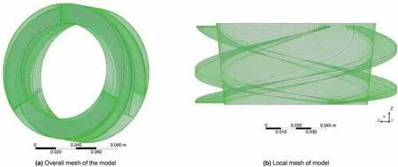
Fig. 4. Impeller grid.
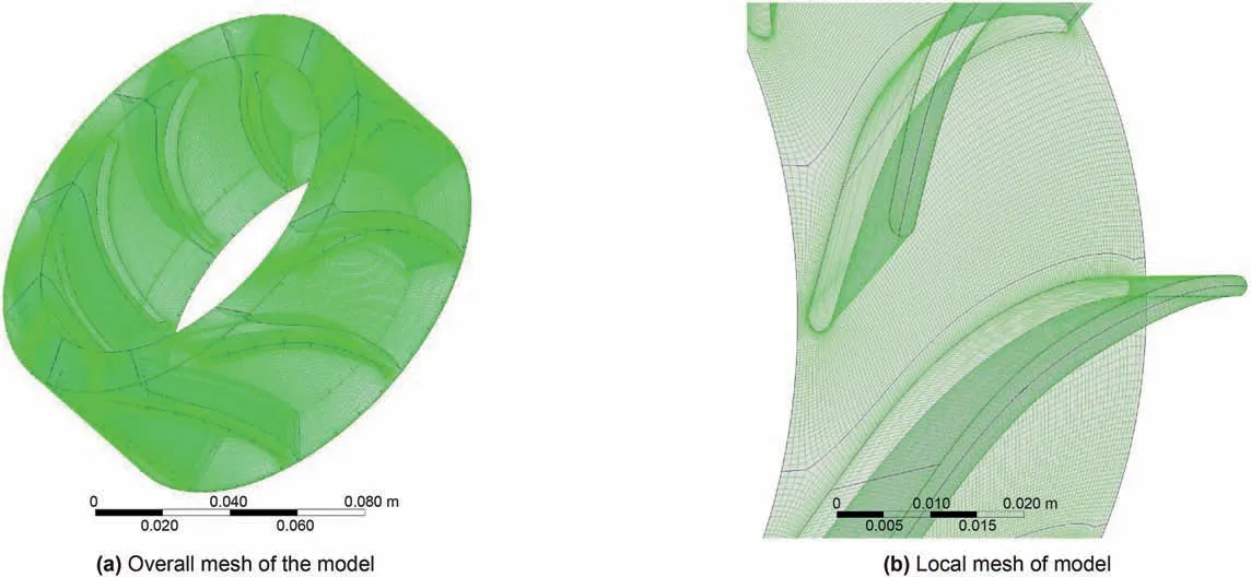
Fig. 5. Diffuser grid.

Fig. 6. The differential pressure curve of multiphase pump at different grid numbers.
The subscript n represents the n phase,which refers water phase when n = l and refers gas phase when n = g. αnis the volume fraction of the n phase,ρnis the density of the n phase,and unis the velocity of the n phase fluid passing through the impeller passageways.fnis the mass force related to the rotation of the impeller,including Coriolis force and centrifugal force, etc. Mnis the interphase force of the n phase.
The relationship between the volume fractions of gas and liquid is shown as follows:
The Reynolds averaged Navier-Stokes method was employed to perform a numerical simulation of the flow field of the helico-axial multiphase pump. SST k-ω model has the characteristics of high calculation accuracy in near wall area and far wall area, and is widely used in engineering practice.SST k-ω model can give a more accurate prediction of flow separation under reverse pressure gradient. Considering that the simulation object of this study has both near wall flow and far wall flow, SST k-ω model is used as turbulence model.In this paper,the slug flow condition is studied,which makes the flow in the pump change sharply,and the average velocity of the flow field is large,which belongs to the range of high Reynolds number, so y+ is taken as 30-300.
3.1.2. Interphase forces
The forces between the liquid and gas phases in the helico-axial multiphase pump mainly include drag force MDn,virtual mass force MAnand lift force MLn.The interphase forces are very complex in the multiphase pump. In the running of the multiphase rotodynamic pump, the magnitude of turbulent dispersion force is negligible relative to the drag, and the lift force are comparable with it(Yu et al., 2015). Considering the stress of bubbles, the lift force MLnof spherical bubbles is zero, and although the lift force of nonspherical bubbles is not zero, these forces cancel each other due to the randomness of each bubble orientation.And the lift force on the gas is relatively small compared with other forces,which can be ignored. At the same time, it also reduces the computational complexity. Therefore, only the drag force and virtual mass force were considered. The calculation method can be described as follows:
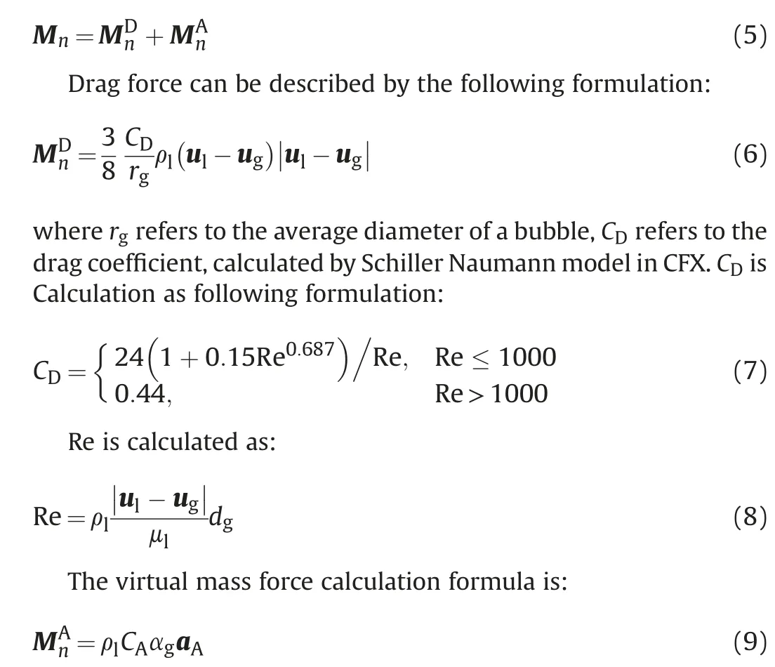
It was assumed that a bubble is spherical, so that CAwas set to 0.5, and aAwas expressed as:

3.2. Boundary conditions
The mass flow rate was set to the inlet condition and the average static pressure was set to the outlet condition of the flow field.The wall surface was set to no-slip boundary conditions. The thermodynamic process in the transportation process was assumed as an isothermal process due to considering the change of temperature between the two phases in the multiphase pump is little.The fluid temperature and the environment temperature in the pump were both set to 25°C.The reference pressure was set to 0.1 MPa in the simulation.The dynamic and static interface was defined as mixed surface using Transient Rotor Stator mode.The impeller speed was set to 2700 r/min. The unsteady calculation time step was set to 0.0001235 s, which meant the impeller rotated 2°for each time step.
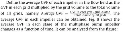
Slug flow is an alternation of Taylor bubbles and liquid slugs.The IGVF of the multiphase pump will continuously rise and fall sharply under slug flow. In order to simulate the inlet conditions of the pump under slug flow,the inlet volume flow rate of the pump was set to keep 33 m3/h and the average IGVF was set to vary from 20%to 80%. Fig. 7 shows the curve of the IGVF in this experiment. The following are aimed to investigate the pump performance changes with Taylor bubbles and liquid plugs flow into the multiphase pump successively.
4. Results and discussion
Under the slug flow condition of the multiphase pump,the IGVF of the pump changes with time, and the flow field in the pump is unsteady. The inlet condition is slug to flow down to analyze the distribution and change of the two-phase flow field in the pump when Taylor bubbles and liquid plugs enter the compression cells,and further explore the unsteady characteristics of the differential pressure of each stage and impeller torque of the multiphase pump.
4.1. Gas distribution inside the compression cells
4.1.1. Variation of average GVF
(1) The average GVF in the first to the third stage impellers is much more than 0.2 with initial working conditions and liquid plug (the GVF is 0.2). This is because the gas-liquid separation occurs inside the impeller. Moreover, gas pocket attached near the hub also lead to the increase of the average GVF in the impeller.This is consistent with the visualization study of Zhang et al. (2016).
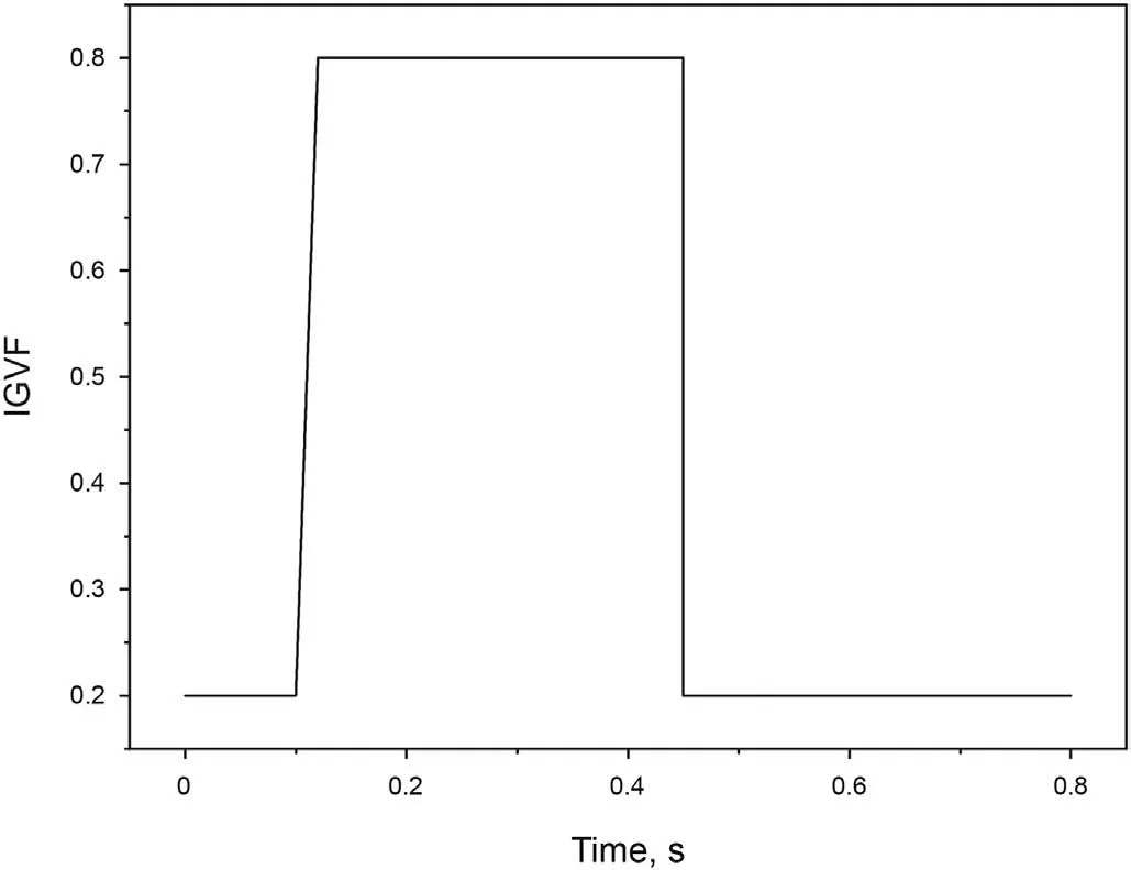
Fig. 7. IGVF of the pump with time.
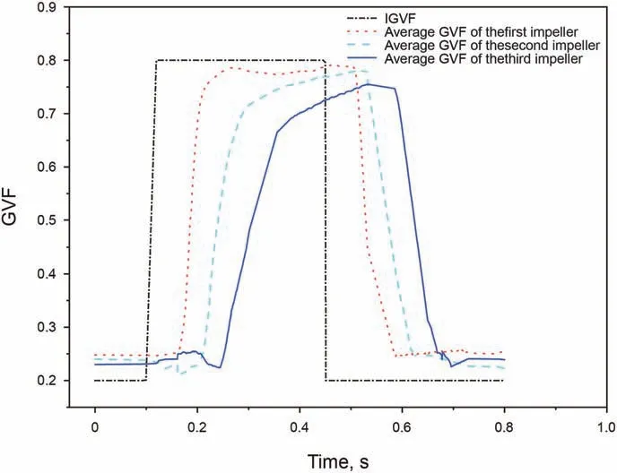
Fig. 8. Average GVF in each stage impeller of the multiphase pump.
(2) The GVF in the first to the third stage impellers changes in the process of the Taylor bubble and liquid plug flowing into the multiphase pump sequentially, and the time difference between fluctuations at all levels is about 0.05s. From the inlet to the outlet of the multiphase pump, the maximum average GVF in each stage of the impeller decreases gradually. This is because the compressibility of the gas is considered and the compressibility of the liquid phase is neglected. The static pressure in the multiphase pump increases stage by stage,and the average GVF in the impeller of each stage decreases stage by stage.
(3) When affected by Taylor bubbles in the slug flow,the average GVF in the first stage impeller increases at a rapid rate,and at about 0.2s, the GVF in the first stage impeller reaches the peak value.Then, it remains basically stable,and the overall trend is basically the same as the trend of IGVF.However,the GVF in the second-stage impeller firstly decrease slightly and then increase in an approximately linear trend. The growth rate of GVF in the second impeller is lower than that of the first-stage impeller, and there is no obvious steady segment before rising to the maximum GVF. Compared with the first two stage impellers, the average GVF in the third stage impeller has the lowest rise rate during the rapid rise period,and after reaching the peak, there will be a slow decline period.
(4) Affected by the liquid plug,the average GVF in each impeller gradually decreases with time, and the rate of decrease is approximately the same.At 0.7-0.8s,the average GVF in the second and third stage impellers is different from the initial working conditions, and the average GVF in the third stage impeller is higher than that in the second stage, which is affected by the Taylor bubbles in the slug flow.
4.1.2. Influence of Taylor bubbles on the GVF in the compression cell at each stage
In order to further analyze the variation of gas distribution in the multiphase pump under the slug flow, the variation of gas distribution when the three-stage impellers are affected by Taylor bubbles was analyzed firstly. The contour of GVF on the revolutionary surface at 0.5 times span was selected for analysis.Fig.9,Fig.10,and Fig.11 show the changes of the GVF from the first-stage to the thirdstage compression cells at 0.5 times span when affected by the Taylor bubbles.
Fig. 9 shows that when the first-stage impeller is affected by Taylor bubbles, the air mass first enters the impeller passageways along the blade suction sides and the air mass is also formed on the blade pressure sides. Then, the air masses on both sides form a whole mass and block the impeller passageway.Subsequently,the whole air mass extends toward the impeller outlet and then flows out of the impeller after being cut by the diffuser blade. The gas distribution in the three flow passages of the first stage impeller is close, and there is no obvious difference.
Fig.10 shows that the gas distribution inside the second-stage impeller is significantly different from the first-stage impeller when affected by Taylor bubbles. Firstly,with the gradual increase of GVF in the diffuser of the previous stage, the diameter of the discontinuous small air mass on the inlet side of the second stage impeller gradually becomes larger. Subsequently, the gases accumulate into gas pocket on the blade pressure sides near the outlet.Finally,the gas pocket extends toward the outlet of the impeller and is cut by the second-stage diffuser. Due to the rotor-stator interaction of the upper stage diffuser,there is a certain difference in the gas distribution between the three passageways of the second stage impeller.With the continuous entry of Taylor bubbles,the diameter and continuity of small bubbles from the upper diffuser to the second stage impeller gradually increase, and the inlet section of the second stage impeller passageways is choked by gas pocket.
Fig.11 shows that the gas distribution in the third-stage impeller is similar to the second-stage impeller when affected by Taylor bubbles. However, compared with the second-stage impeller, the position of the air mass on the blade pressure sides of the thirdstage impeller is closer to the inlet of the impeller and the air mass extends faster toward the outlet of the impeller. The difference of gas distribution between different passageways in the third-stage impeller is more obvious.
4.1.3. The influence of liquid plug on the GVF in each stage compression cell
As the liquid plug flows into the multiphase pump, the GVF in the three-stage compression cell changes with time as shown in Fig.12, Fig.13 and Fig.14.
Fig.12 shows that the regions of low GVF first appear at the inlet of the first-stage impeller near the blade pressure sides when liquid plugs flow into the impeller.Subsequently,regions of low GVF also appear at the inlet of the impeller close to the blade pressure sides.Then,the regions of low GVF extend along the blade pressure sides to the outlet of the impeller,and the gas in the impeller passageway is distributed in the middle of the passageway in the form of discontinuous small air masses. On the blade pressure sides about 1/2 chord to the outlet, the gas accumulate to air mass with irregularly shapes. And the volume of the air mass continues to decrease until the air mass disappears with the inlet low.
Fig.13 shows that when the liquid plug flows into the secondstage impeller, the gas accumulate to a series of discontinuities small air masses close to the blade pressure sides and gradually extend toward the outlet due to the influence of the compression cell diffuser of the first-stage impeller. At the same time, the gas accumulates near the blade pressure sides at the outlet side of the impeller to form air mass,which is continuously cut by the secondstage diffuser blade and enters the second-stage diffuser passageway.The liquid phase flows close to the suction sides of the blade and forms a series of discontinuous regions of low GVF on the suction sides.
Fig. 14 shows that the gas distribution inside the third-stage impeller is similar to that of the second-stage impeller. The difference is that the gas-liquid two-phase separation inside the thirdstage impeller is weaker and the area of high GVF and low GVF regions is lower than the first and second stages.
4.2. Analysis of differential pressure of the multiphase pump
Fig. 15 shows the variation of the differential pressure of the multiphase pump under slug flow with time. It can be seen from the figure that the differential pressure of the multiphase pump remains basically stable with slight fluctuations when the IGVF is low, but the overall stability is basically stable. As Taylor bubbles flows into the multiphase pump, the differential pressure of the pump first rises slightly and then drops sharply,the rate of drops is fast firstly and then slow, and the process is accompanied by fluctuations. As the Taylor bubbles continues to leave and the liquid plug continues to flow in,the differential pressure of the pump rises rapidly after reaches the minimum.
Fig. 16 shows the differential pressure curve of each stage compression cell with time under slug flow,it can be seen from the figure:
(1) The differential pressure of the first-stage compression cell drops rapidly when affected by Taylor bubbles, and then remains stable and accompanied by slight fluctuations after reaches the lowest point. However, when liquid slugs flow into the first-stage compression cell,the differential pressure of the first compression cell increase rapidly, and then basically remains stable.
The girl didn t know what to do, and began to cry; then the door opened as before, and the tiny little man appeared and said: What ll you give me if I spin the straw into gold for you? The ring from my finger, 20 answered the girl
(2) When the second-stage compression cell is affected by Taylor bubbles in the slug flow, the differential pressure of the second stage compression cell first increases slightly, and decreases rapidly, finally decreases slightly until to the minimum value. Accordingly, it can be seen from Fig. 8 that the GVF in the second-stage impeller just dropped slightly at this time.Fig.17 shows the gas distribution in the first-stage compression cell and the second-stage impeller during this period. It can be analyzed from Fig. 17 that the GVF in the first-stage diffuser increases at this time, and the volume of bubbles flowing into the second-stage impeller decreases.These results suggest that when the first-stage impeller is affected by Taylor bubbles, the ability of the vortex to accumulate gas in the first-stage diffuser is strengthened, which leads to the decrease of the gas flowing into the second-stage impeller. Therefore, for the second-stage impeller, the GVF decreases and the differential pressure rises. With the continuous outflow of Taylor bubbles and the continuous inflow of liquid plugs,the differential pressure of the secondstage gradually increases after reaching the lowest point.
Fig. 9. GVF variations of the first stage impeller affected by Taylor bubbles.
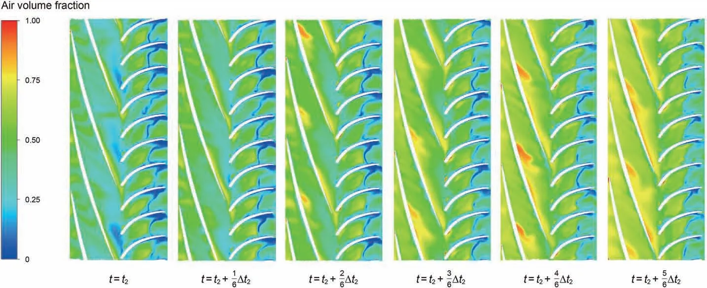
Fig.10. GVF variations of the second stage impeller affected by Taylor bubbles.
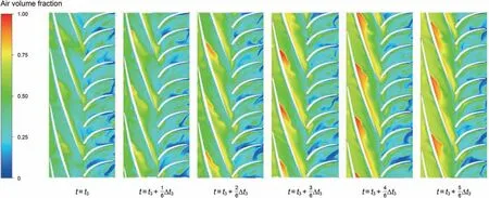
Fig.11. GVF variations of the third stage impeller affected by Taylor bubbles.
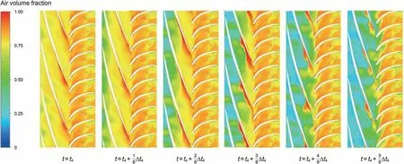
Fig.12. The change of GVF when the first stage impeller is affected by the liquid plug.
(3) The variation of the differential pressure of the third compression cell is similar to that of the second-stage.Compared with the second-stage, the differential pressure of the third compression cell increases more during the ascending phase and the overall fluctuation is more intense.This is because the differential pressure of the impeller will fluctuate due to the influence of rotor-stator interaction interference on the upstream.That is to say,the rotor-stator interaction between the first-stage diffuser and the secondstage impeller will indirectly affect the third stage after passing through the second compression cell.Therefore,the differential pressure of the third-stage impeller fluctuates sharply due to the effect of rotor-stator interaction between the first and second stages,and the second and third stages.
4.3. Torque analysis of each stage impeller
Fig.18 shows the torque curve of the three stage impellers with time. From the figure, it can be seen that: Under steady working condition with low GVF,the torque on the impellers of all stages in the pump has fluctuations,and the fluctuation of the torque of the second and third stage impellers is larger than that of the first stage impeller. Due to fluctuations of blade induced by the large difference in gas distribution in the second and third stage impellers,the fluctuations of the torques of the second and third stage impellers are significantly enhanced compared with the first stage impellers.In the process of Taylor bubbles flowing into the pump,the torque of the three stage impellers drops rapidly. Among them, the first stage impeller drops faster while the second and third stage impeller torque is accompanied by severe fluctuations.The reason for this difference is that the second and third stage impellers are affected by the rotor-stator interaction on the upstream dynamic and static interface. Based on this, the gas enters as a series of independent air masses, which makes the impeller torque fluctuate violently.
5. Fluid-structure interaction calculation and analysis
5.1. Solid domain model and grid of the multiphase pump rotation system
Under slug flow conditions, the main shaft and impeller blades of the multiphase pump have static deformation characteristics.Due to there is no interaction force between the diffuser and the shaft,the diffuser components are omitted when building the solid domain model.The torque is transmitted between the pump shaft and the impeller through flat keys. The overall model and grid of the solid domain of the pump rotation system are shown in Fig.19.
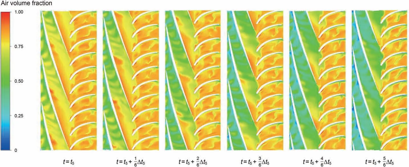
Fig.13. The change of GVF when the second stage impeller is affected by the liquid plug.
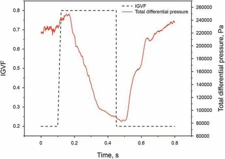
Fig.15. Differential pressure variations of the multiphase pump.
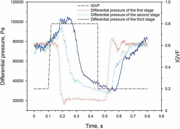
Fig.16. Differential pressure variations of each compression cell.
5.2. Material properties
According to the actual processing, the material of the shaft selected in this paper is gray cast iron, and its material properties are shown in Table 2.
5.3. Loads and constraints
There are mainly three kinds of loads of the pump:1)centrifugal load, 2) gravity load, and 3) hydrodynamic force.The specific constraints and loads imposed on the pump in this paper are as follows:
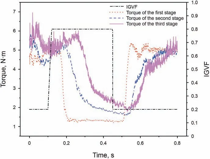
Fig.18. Torque variations of the three-stage impellers.
(1) Cylindrical constraints: Cylindrical restraints are applied at the bearings installed at both ends of the pump to limit the freedom of the shaft in the radial and axial directions.
(2) Displacement constraint: For the actual multiphase pump,the shaft is constrained by thrust bearings, diffuser and the inlet volute of the pump body and cannot be moved axially.In this paper,some parts of the pump body are simplified,so the displacement constraint is imposed to the impeller end face to ensure that the impeller cannot move axially.
(4) Centrifugal load:The rotational speed of the impeller and the pump axis is defined to apply the centrifugal load to it, the rotation axis is set to the z-axis,and the rotation speed is set to 2700r/min.
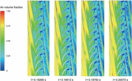
Fig.17. GVF variations of the first-stage compression cell and the second-stage impeller(Taylor bubbles flows into the first-stage impeller, 0.5 times span).

Fig.19. Solid-domain grid of the rotation system.

Table 2 Material properties of multiphase pump.
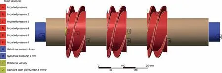
Fig. 20. Schematic diagram of load and constraint of the multiphase pump.
(5) Hydrodynamic force:the simulation results of the flow field at different times are loaded into the solid domain of the multiphase pump according to coupling system. The coupling surfaces include the impeller blade surface and the impeller hub.
Finally, the load and constrained loading on the pump are shown in Fig. 20.

Fig. 21. The maximum deformation of the main shaft of the pump.
5.4. Results of fluid-structure interaction
Fig.21 shows the variation of the maximum deformation of the main shaft of the multiphase pump with time. It can be seen that the maximum deformation of the main shaft of the multiphase pump shows sinusoidal change under the influence of the Taylor bubbles in the slug flow, and the peak appears in the first stage impeller. Under the influence of the incoming Taylor bubbles, the peak value at this time increases by 10.9% relative to the steadystate operating condition of the IGVF. As the Taylor bubbles gradually enters the second and third stages of the compression cell,the maximum deformation of the main shaft slowly rises, and the maximum deformation of the main shaft increases when the multiphase pump is affected by the liquid plug.
6. Conclusions
In view of the slug flow conditions in the multiphase pump,the internal flow characteristics of the slug flow with a high and low IGVF are studied, and the following conclusions are obtained:
(1) When the pump is affected by Taylor bubbles in the slug flow,the variation of the gas distribution in the three-stage impellers is different. The gas in the first stage impeller forms an atmospheric mass with blocking effect in the blade channel and extends to the outlet side of the impeller. The gas distribution in the second stage impeller is similar to that in the third stage impeller. The independent Taylor bubbles volume becomes larger and the continuity is enhanced.And the gas first accumulates into an air mass near the outlet end on the pressure side of the blade, and then extends toward the impeller outlet.
(2) When the first stage impeller is affected by Taylor bubbles,the differential pressure of the first stage impeller decreases rapidly and then stays stable. However, for the second and third impeller, the internal average GVF decreases slightly and the differential pressure increases when the upper impellers are affected by the Taylor bubbles.
(3) The torque of the three-stage impellers in the pump successively decreases in the process of Taylor bubbles flowing into the pump.
(4) The maximum deformation of the pump shaft shows a sinusoidal change when it is affected by Taylor bubbles, and gradually increases with the inlet liquid plug,and the peak value increased by 10.9%relative to the conditions of the low IGVF. As the liquid plug flows into the pump, the maximum deformation is increased.
(5) The gas-liquid two-phase flow pattern in the pump changes drastically under slug flow, which resulting in dramatic fluctuations in the differential pressure of the pump and the torque and deformation of the shaft. On this base, the performance and reliability of the pump would be affected.
Conflicts of interest
There are no conflicts of interest with other people or organizations that may inappropriately influence the author’s actions.
Acknowledgments
The authors would like to acknowledge the support of the National Key R&D Program of China (Grant No.2020YFB2010002).
杂志排行

Petroleum Science的其它文章
- A fast space-time-domain Gaussian beam migration approach using the dominant frequency approximation
- Predicting gas-bearing distribution using DNN based on multicomponent seismic data: Quality evaluation using structural and fracture factors
- Reflection-based traveltime and waveform inversion with secondorder optimization
- Determination of dynamic capillary effect on two-phase flow in porous media: A perspective from various methods
- Settling behavior of spherical particles in eccentric annulus filled with viscous inelastic fluid
- Laboratory investigation on hydraulic fracture propagation in sandstone-mudstone-shale layers