Theoretical research on gas seepage in the formations surrounding bedded gas storage salt cavern
2022-09-23XingShengChenYinPingLiLongJingYunXiLiuToZhng
Xing-Sheng Chen , Yin-Ping Li , Y-Long Jing , Yun-Xi Liu ,c, To Zhng
a State Key Laboratory of Performance Monitoring and Protecting of Rail Transit Infrastructure, East China Jiaotong University, Nanchang 330013, Jiangxi,China
b State Key Laboratory of Geomechanics and Geotechnical Engineering,Institute of Rock and Soil Mechanics,Chinese Academy of Sciences,Wuhan 430071,Hubei, China
c University of Chinese Academy of Sciences, Beijing 100049, China
Keywords:Gas storage salt cavern Seepage Tightness Non-Darcy's law Leakage
ABSTRACT When constructing salt cavern gas or petroleum storage in lacustrine sedimentary salt formations rich in mudstone interlayers, the influence of the sealing performance of interlayers and salt-mud interface on the storage tightness should be considered adequately. In order to reveal the gas seepage in deep formations surrounding bedded salt cavern underground storage,a leakage analysis model was established based on the characteristics of a low dip angle and the interbedded structure of bedded rock salt.The gas seepage governing equations for one-dimensional and plane radial flow were derived and solved. A gas seepage simulation experiment was conducted to demonstrate the accuracy and reliability of the theoretical calculation results. The error of the seepage range was approximately 6.70%, which is acceptable. The analysis and calculation results indicate that the motion equation of gas in deep formations satisfies a non-Darcy's law with a threshold pressure gradient and slippage effect.The sufficient condition for the gas flow to stop is that the pressure gradient is equal to the threshold pressure gradient.The relationship between the leakage range and operating time is a positive power function, that is, the leakage range gradually increases with time and eventually stabilizes.As the seepage range increases,the seepage pressure decreases sharply during the early stage, and then decreases gradually until the flow stops.Combining the research results with engineering applications, three quantitative evaluation indexes named the maximum admissible leakage range, leakage volume and leakage rate are proposed for the tightness evaluation of gas storage salt cavern during their operating stage. These indexes can be used directly in actual engineering applications and can be compared with the key design parameters stipulated in the relevant specifications. This work is expected to provide theoretical and technical support for the gas loss and tightness evaluation of gas storage salt caverns.
1. Introduction
The structure of energy consumption in China is still dominated by coal, which accounts for more than 60% of the primary energy.The basic characteristics of the energy structure of China are rich in coal and lack natural gas and petroleum (Hao et al., 2015; Li and Leung, 2012; Shaikh et al., 2017). This leads to a series of problems such as a low utilization of coal, severe pollution and dust generation, and an inadequate petroleum and gas reserve system.Therefore, in response to the thirteenth Five-Year Plan for Energy Development, the National Energy Administration of China indicated that the proportion of coal consumption should be reduced to less than 58% from 2016 to 2020. The proportion of natural gas consumption should reach 10%, while the consumption of nonfossil energy should increase to over 15% (Liu et al., 2020; Wei et al., 2020). Furthermore, the energy consumption should be transformed into a clean, low-carbon, safe, and efficient system to reduce the greenhouse effect and promote the healthy and stable development of energy. In the context of energy transformation and clean energy utilization, ensuring a smooth transition from coal to gas and guaranteeing a safe supply of clean energy has become the primary problem faced by many countries (Burke and Yang, 2016; Dilaver et al., 2014).
Salt rock underground storage is a cavern leached from salt domes or salt-bedded formations,it is used to store oil,natural gas or other hydrocarbons (Fan et al., 2019, 2020; Li et al., 2017; Pinto et al., 2021). Owing to the advantages of a large storage capacity,seasonal peak regulation,flexible storage and low investment costs,gas storage salt caverns feature the most rapid rate of increase of working gas and daily gas production among all types of underground storages. As an underground engineering for deep energy storage, the most important problem of salt cavern storage is ensuring its tightness and stability(Chen et al.,2021).As shown in Fig. 1, because of the difference between the ground stress and time-varying operating pressure, the storage may not only suffer roof collapse because of lack of structural stability, but it may also may face the risk of gas leakage due to tightness failure. Surface subsidence, fire and explosions caused by accidents seriously threaten the lives and property of nearby residents. The results in literature and leakage accident statistics show that between 1969 and 2019, there were approximately 20 leakage accidents of gas and petroleum in salt cavern underground storages (B′erest et al.,2019; Evans, 2009; Osnes et al., 2007; Yang et al., 2013). The causes of leakage include casing rupture, interlayer and cap rock fracture, surface facility damage and human errors.
Because of the different depositional environments of bedded rock salt and salt domes (Fig. 2), researchers have focused on studying leakage accidents and tightness evaluations in gas storage salt cavern.With regard to salt dome storage,research has focused on the damage, dislocation and interface slippage of rock salt crystals, based on which relevant theories have been proposed(Alkan, 2009; Hunsche, 1998). For example, Stormont (1997)divided the excavation damage zone and undisturbed zone according to the on-site permeability of rock salt. The permeability parameters of the rock salt in the excavation damage zone increased, while the undisturbed zone maintained its original sealing ability. Müller et al. (2018) simulated the damage of rock salt on the crystal scale using the discrete element method. Their analysis results were verified by uniaxial compression and acoustic emission tests. Osnes et al. (2007) discussed a case history of a casing failure in a gas storage salt cavern,and confirmed that strains of sufficient magnitude can cause tensile failure in the lower portion of the cased well. Evans (2009) collected statistics on the leakage accidents, casualties and economic losses of salt dome storages,and described the entire process of these accidents.
Compared with the salt dome formed by marine sedimentation,the bedded rock salt has more interlayers,thinner salt strata and a higher content of insolubles, which complicates the evaluation of tightness and stability (Zhang et al., 2017). For bedded salt cavern storage,one needs to pay more attention to the leakage range and rate of storage media such as petroleum and natural gas, and the study of the permeability of interlayers is an indispensable part of the tightness evaluation (Huang and Xiong, 2011; Wang et al.,2018). Based on Darcy's law and porous media seepage theory,Wang et al.(2015a),Liu et al.(2016)and Xiong et al.(2015)analyzed the pressure distribution and seepage of gas in formations by means of numerical simulation,and pointed out that the interlayers will accelerate gas leakage.A large number of test results show that although the permeability of well-integrated interlayers is slightly higher than that of rock salt,it is fully capable of sealing petroleum and natural gas(Li et al.,2014;Liu et al.,2015;Yin et al.,2017).Their permeability range is about 10-17to 10-20m2. The formations surrounding storage salt cavern are dense porous media, and the gas flow in such formations is extremely slow and does not satisfy Darcy's law. Many factors affect gas seepage and leakage, such as the threshold or critical pressure gradient, Klinkenberg effect,effective volume of storage cavern, permeability and mechanical parameters of formations. The threshold pressure gradient is the threshold at which the fluid starts to flow in a tight formation.This phenomenon often occurs in low-permeability formations and is an influencing factor that must be considered for fluid seepage in such formations(Kong,1999).
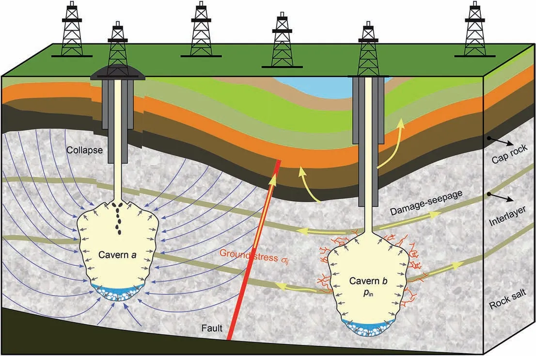
Fig.1. Schematic diagram of gas leakage and roof collapse in salt cavern underground storage (B′erest, 2017; B′erest et al., 2019).
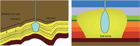
Fig. 2. Bedded rock salt formations of lacustrine depositions and salt dome of marine depositions.
The purpose of this study was to analyze the long-term and large-scale seepage of gas in formations surrounding salt caverns,and thus propose several quantitative indexes for tightness evaluations during the operating stage.A leakage analysis model of a gas storage salt cavern was established and a gas seepage governing equation considering the threshold pressure gradient and slippage effect was derived. The validity of this theoretical model and the calculation results were verified base on a seepage simulation experiment. Finally, an on-site bedded gas storage salt cavern in Jintan,China,was selected for the gas loss and tightness evaluation based on the leakage analysis model. Combined with operational conditions and calculation parameters, the tightness evaluation indexes, such as gas leakage range, leakage volume and rate were obtained.The research contents and results provide theoretical and experimental support for site selection, key design parameters(typically pillar width and thickness of salt roof) and tightness evaluation of bedded gas storage salt cavern.
2. Leakage analysis model of bedded gas storage salt cavern
Considering the low dip angle and the interbedded structure of bedded rock salt, a leakage analysis model for gas seepage in formations surrounding bedded salt cavern was established.As shown in Fig.3,this model includes not only rock salts and interlayers,but also the salt roof, salt bottom and cap rock. The roof is the salt retained at the top of a salt cavern after leaching,and the bottom is the undissolved salt at the bottom of the salt cavern.The gas stored in salt caverns usually is natural gas, ethylene or hydrogen. The stored gas seeps along the surrounding formations into pores and fractures under the action of the operating pressure.Rock salts and interlayers with poor sealing performance may become potential channels for gas leakage.
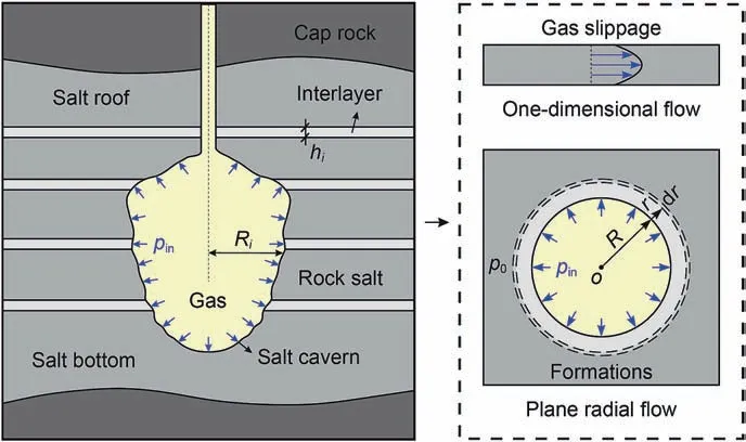
Fig.3. Leakage analysis model for gas seepage in formations surrounding a salt cavern,hi indicates the thickness of a certain formation, Ri represents the cavern radius at a certain formation, pin and p0 are the operating pressure of salt cavern and initial pore pressure in the formation.
2.1. Equivalent permeability of bedded rock salt
As an interbedded rock mass, the mechanical and permeability characteristics of bedded rock salt are determined by the interlayers and rock salt.Yang et al.(2005)and Li et al.(2014)found that the salt-mudstone interface of bedded rock salt is well cemented and is unlikely to open or slip according to extensive mechanical property tests.This is different from the joints or weak structural surfaces of other layered rocks. Furthermore, the mudstone interlayers can effectively restrain the creep shrinkage of a salt cavern because of its high elastic modulus compared with that of rock salt. Similarly, the permeability of bedded rock salt is not only related to the interlayer and rock salt,but also depends on the seepage direction of the penetrating fluid. As shown in Fig. 4,the vertical and horizontal seepage can be used as examples to establish an equivalent permeability model for bedded rock salt.The length, width and height of this model are l, w and h,respectively.The horizontal seepage in the equivalent permeability model refers to the gas flow in which the seepage is parallel to the formation. The pressure gradient ∇p of the gas flowing through each formation is the same, and the total flow rate Q is the sum of the flow rate Qiof each formation.Assuming that the total flow rates of the interlayers and rock salts are Qmand Qs, the following relationship can be obtained based on Darcy's law:
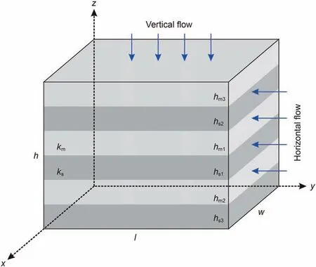
Fig. 4. Equivalent permeability model of bedded rock salt.
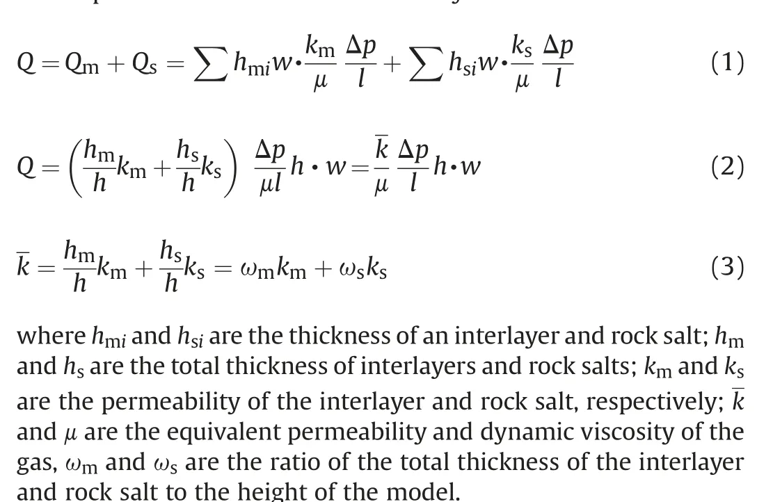
Eq. (3) shows that the equivalent permeability of bedded rock salt under horizontal seepage is equal to the sum of the product of the permeability kiand thickness ratio ωiof rock salts and interlayers, which means that the high permeability formation controls the equivalent permeability of the bedded rock salt. The tightness of a salt cavern is determined by the interlayer because of its relatively poor sealing performance compared with that of rock salt.
Vertical seepage in the equivalent permeability model refers to the gas flow in which the seepage direction is perpendicular to the formation. Its characteristics are that the flow rate Q of the gas flowing through each formation is the same, and the pressure gradient ∇p is the sum of the pressure gradients Δpiof each formation. The flow rate can be expressed as follows:
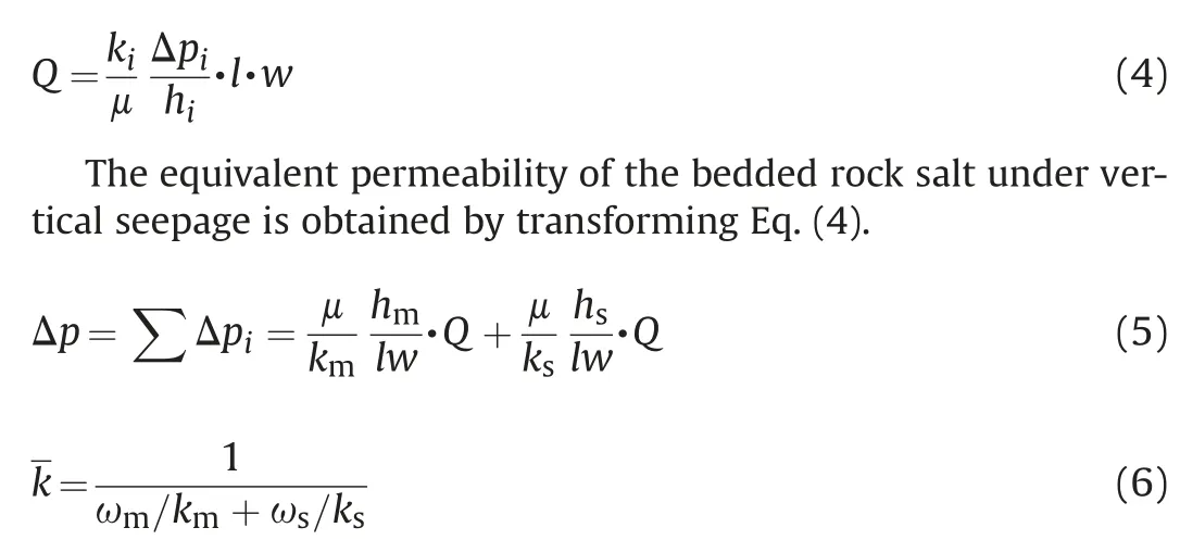
The equivalent permeability of bedded rock salt in the case of vertical seepage is determined by the low permeability formation,which means that the tightness of a salt cavern can be guaranteed as long as a certain formation does not leak.
Most formations surrounding bedded salt cavern storage are approximately horizontal because of the lacustrine deposition of these bedded salt formations (Chen et al., 2019; Lankof and Tarkowski, 2020; Zhang et al., 2015). Hence, the gas seepage in the formations surrounding a salt cavern can be regarded as a plane radial flow,that is,horizontal seepage.The vertical seepage mainly exists in the top and bottom of a salt cavern.
2.2. Klinkenberg effects of gas flow in porous media
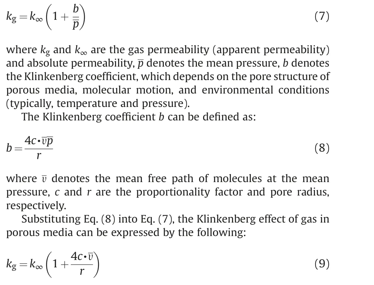
The gas flow in porous media is different from that of liquid,which is mainly manifested in the compressibility and slippage effect. In 1941, Klinkenberg (1941) revealed the gas slippage phenomenon in porous media based on his theoretical seepage analysis of ideal gas flow, thus the slippage effect is also called the Klinkenberg effect.Many scholars have also found this phenomenon by means of permeability tests on cores (Al-Jabri et al., 2015; Chen et al., 2015; Zhao et al., 2019). The test results indicate that the Klinkenberg effect increases the apparent permeability of porous media,and the denser the rock and the lower the seepage pressure,the more obvious the Klinkenberg effect. Because the formations surrounding salt caverns are tight porous media, the Klinkenberg effect cannot be ignored when analyzing gas seepage in them.
The Klinkenberg effect is the result of frequent collisions between the gas molecules and the pore wall of porous media, such that the gas velocity on the pore wall is not zero, that is, the nonslip condition is not satisfied. The influence of the Klinkenberg effect on gas seepage can be described by the following equation(Klinkenberg,1941):
2.3. Boundary conditions
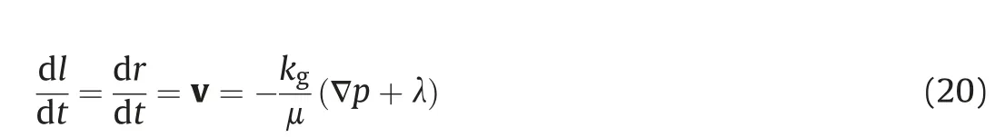
The depth of gas storage salt cavern in China is approximately greater than or equal to 800 m,hence the formations surrounding the salt caverns are deep and tight.The flow velocity of the fluid in these formations is extremely low, resulting in the equation of motion that does not satisfy Darcy's law. The precondition of fluid flow in low-permeability formations is that the seepage pressure gradient exceeds the threshold pressure gradient in the formation,otherwise the fluid cannot flow(Li et al.,2020; Wang et al., 2011).The equation of motion of gas seepage in a tight formation can be expressed as:

where v is the seepage velocity or Darcy's velocity, μ denotes the dynamic viscosity of the flowing gas,and λ denotes the threshold or critical pressure gradient, with a positive value.
For Newtonian fluids,the above equation of motion can only be applied at low speeds, which usually occurs in low-permeability formations. In the running stage of a gas storage salt cavern, the operating pressure changes dynamically with the gas injection and production. Assuming that the operating pressure and the initial pore pressure of the formations are pinand p0, then the pressure boundary conditions can be obtained based on the gas seepage characteristics of one-dimensional flow and plane radial flow(Fig. 3).
Pressure boundary conditions of one-dimensional flow:
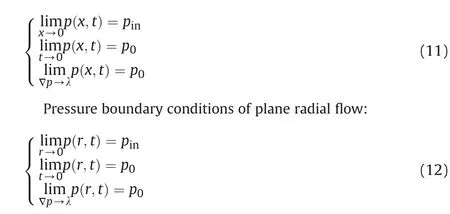
where x and r are the distance of one-dimensional flow and plane radial flow, pinand p0are the operating pressure and initial pore pressure in the formations, respectively.
2.4. One-dimensional flow
Before the theoretical analysis,considering that the complexity of the underground environment and the uncertainty about the actual situation will make the theoretical solution difficult, the following basic assumptions are proposed.
1. Bedded rock salt formations are interbedded structures, in which the gas seepage direction is mainly horizontal.
2. The gas satisfies the ideal gas state equation and the seepage is isothermal.
3. Equation of motion of gas satisfies non-Darcy's law taking into account the Klinkenberg effect and threshold pressure gradient.
4. The compressibility of the rock skeleton is much smaller than that of gas, hence any strata deformation is ignored.
Taking the volume element dV of the surrounding formations for mass conservation analysis of the gas,the continuity equation of gas seepage is as follows:
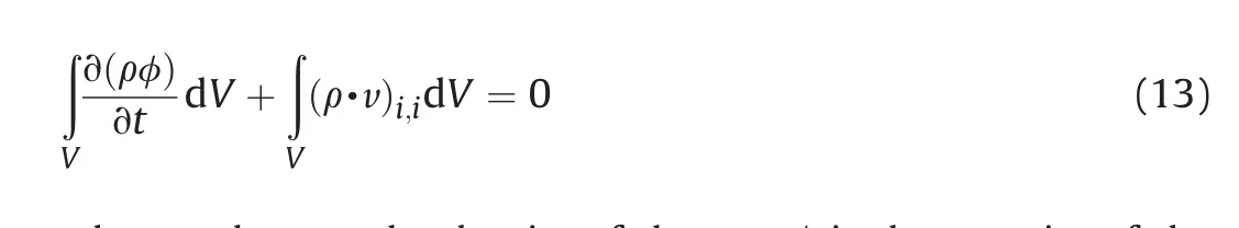
where ρ denotes the density of the gas, φ is the porosity of the porous media.
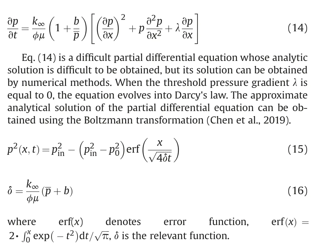
Based on the above assumptions,substituting the ideal gas state equation and the motion equation in Eq. (10) into Eq. (13), the following equation is obtained:
2.5. Plane radial flow
The analysis of the plane radial flow of gas in formations is similar to that of one-dimensional flow. Taking the volume ring element for fluid mass balance, the continuity equation of the unsteady plane radial flow can be obtained:
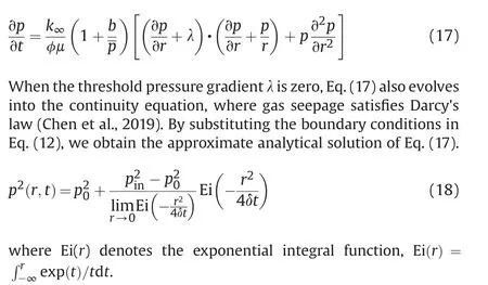
Wu et al.(1998)obtained an approximate analytical solution of seepage pressure under a plane radial flow by using to the heat conduction problem (Carslaw and Jaeger,1992).

where J0and Y0are the Bessel functions of order 0 of the first and second kind,respectively,r and R are the radial distance and cavern radius, and u is the integral variable.
3. Results and validation of the theoretical model
Because the gas seepage in deep formations is more complicated and does not satisfy Darcy's law, the analytic solution cannot be found in the continuity equations.In order to verify and analyze the feasibility of the theoretical model for bedded salt cavern underground gas storage leakage analysis,this model needs to be solvednumerically. The operating conditions and calculation parameters are taken from an in-service gas storage salt cavern in China, as shown in Table 1.
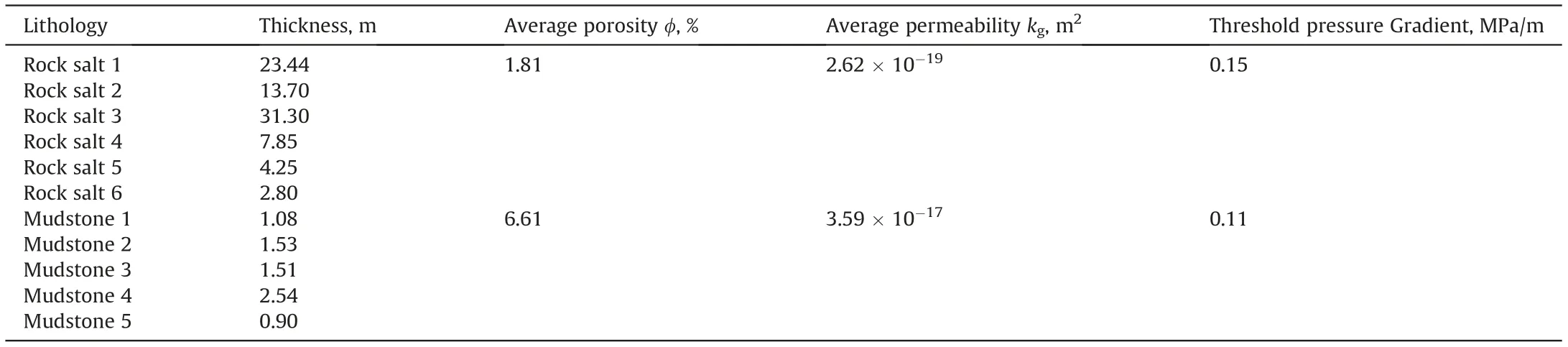
Table 1 Calculation parameters and strata information.
The target salt cavern is located in the eastern coastal area of China. The salt formation is distributed from northeast to southwest, and the salt formation is thick in the middle and thin in the periphery. The nitrogen leak test (NLT) was used for the tightness test. It can evaluate the leakage of salt cavern based on leakage velocity and gas-liquid interface displacement.This salt cavern has five interlayers and six rock salt formations. The corrected sonar detection data show that the maximum radius and effective volume of this cavern are 31.40 m and 152010.51 m3. The correction method takes the mean value from multiple measurements. The interlayers are gray mudstone of varying thickness, with a maximum thickness of 2.54 m and a minimum thickness of 0.90 m.The average gas permeability kg, average porosity φ, threshold pressure gradient λ and other parameters required for leakage analysis of the selected gas storage salt cavern are listed in Table 1.
3.1. Pressure drop
The design range of the operating pressure of the selected salt cavern is 8-16 MPa, and its service life is 30 years. To reduce the number of repeated calculations, the initial operating pressure is taken as the average of the maximum operating pressure and the minimum operating pressure, that is, 12 MPa. By substituting calculation and operation parameters into Eq. (14) and Eq. (17)respectively, the pressure drop of the gas in deep formations can be obtained by numerical calculation. Figs. 5 and 6 show the pressure drop curves of gas in mudstone 1 (interlayer 1) and rock salt 1 under one-dimensional flow and under plane radial flow,respectively.As the flow distance increases,the seepage pressure of the gas decreases sharply in the early stage, and then decreases gently until the flow stops.Because the sealing performance of the rock salt is better than that of the mudstone interlayers, the pressure drop in the salt rock is more severe.In the same formation,the pressure drop of gas under plane radial flow also changes more drastically than that under one-dimensional flow.
3.2. Leakage range
Because the gas flow in deep formations does not satisfy Darcy's law,the sufficient condition for gas flow to stop is no longer that the pressure gradient is equal to 0,but that it is equal to the threshold pressure gradient of the targeted formation. In other words, the leakage range of gas in the formations is equal to the flow distance when the pressure gradient becomes equal to the threshold pressure gradient. The basis of the judgment is as follows:
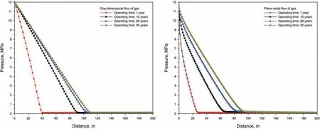
Fig. 5. Pressure drop curve of gas in mudstone 1 under one-dimensional flow and plane radial flow.
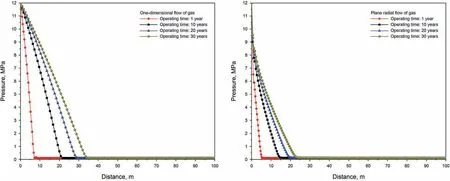
Fig. 6. Pressure drop curve of gas in rock salt 1 under one-dimensional flow and plane radial flow.

Fig. 7. Fitting curve of gas leakage range in interlayer and rock salt under one-dimensional and radial flow.
The results indicate that the leakage range of gas in the surrounding formation has a positive power function relationship with the operating time (Fig. 7), the leakage range increases with time and eventually becomes stable. When the operating pressure and time are 12 MPa and 30 years, the leakage range in the interlayer and rock salt are respectively 69.00 and 22.58 m under plane radial seepage, hence the leakage range of gas in an interlayer is approximately 3.06 times that in rock salt. In the case of the same formation and operating conditions,the leakage range of gas under one-dimensional flow is approximately 1.55 times to 1.65 times that under plane radial flow. These results are consistent with the pressure drop trends (Figs. 5 and 6). According to the distribution characteristics of bedded rock salt and the shape of gas storage salt cavern (Fig. 1), it is known that the plane radial flow or twodimensional axisymmetric flow is more in line with the actual situation than one-dimensional flow. Therefore, the subsequent studies in this paper are based on the plane radial flow, and no longer discuss one-dimensional flow.
3.3. Leakage rate
In addition to the pressure drop and leakage range,the leakage rate of gas in gas storage salt cavern can be roughly calculated according to the leakage analysis model. Absolute leakage mass and rate are the key indicators for leakage risk prevention,and play an important role in the safety evaluation of underground gas storage salt cavern.However,since the service life of gas storage salt cavern is approximately 30 years, the gas leakage risk evaluation and prediction are long processes. The maximum admissible leakage rate is different at different operating stages.There are some limitations in using absolute leakage indicators to evaluate the tightness of salt cavern,which cannot fully reflect the leakage situation,especially the leakage causes and types.Therefore,the leakage rate of gas in this study is not the leakage velocity,but is defined as the percentage of the total leakage volume of a gas storage salt cavern to the storage capacity. The introduction of relative leakage indicators can distinguish storage leakages of different sizes and operating pressures, and can compensate for the lack of absolute indicators. If the two are used in combination, a comprehensive analysis and evaluation of the effect of leakage can be achieved.
The storage capacity of a salt cavern can be defined as the gas reserve under the maximum allowable operating pressure. The value converted to standard atmospheric pressure is as follows:

where Csdenotes the storage capacity of a salt cavern,Veand psare the effective volume of the salt cavern and standard atmospheric pressure.
As shown in Fig.8,most of the leaked gas remains in the pores and cracks of the formations.According to the law of conservation of mass, we can obtain the leakage mass of gas in a certain formation.
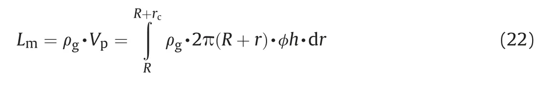
where Lmdenotes the leakage mass of gas, R and rcare cavern radius and leakage range,h and φ are the thickness and porosity of the formation, respectively.
Based on Boyle's law, the leakage volume at standard atmospheric pressure can be expressed as follows:

where LVand LVTare the leakage volume of a certain formation and the total leakage volume of the gas storage salt cavern, n denotes the number of formations surrounding the salt cavern.
We obtain a tightness evaluation index of the total leakage volume of the gas storage salt cavern as a percentage of storage capacity, that is, the leakage rate.
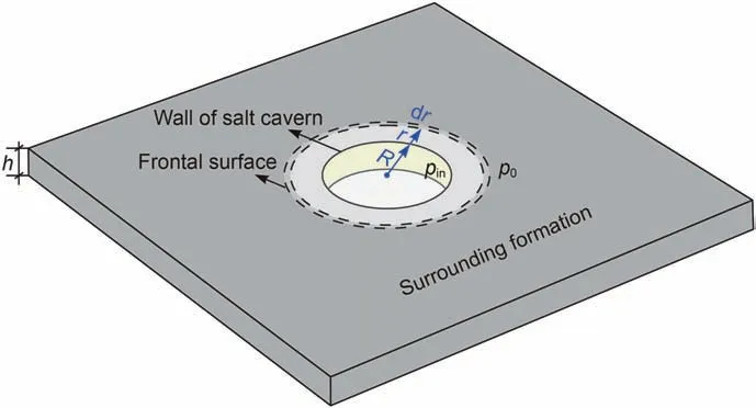
Fig. 8. Plane radial flow of gas in a formation surrounding a gas storage salt cavern.
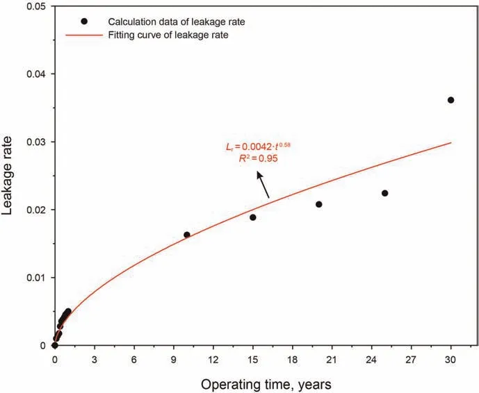
Fig. 9. Leakage rate of this gas storage salt cavern.
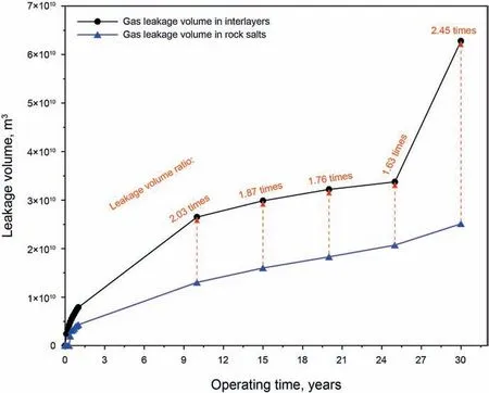
Fig.10. Leakage volume and leakage volume ratio of interlayers and rock salts,leakage volume ratio refers to the total leakage volume of gas in interlayers divided by that in rock salts.
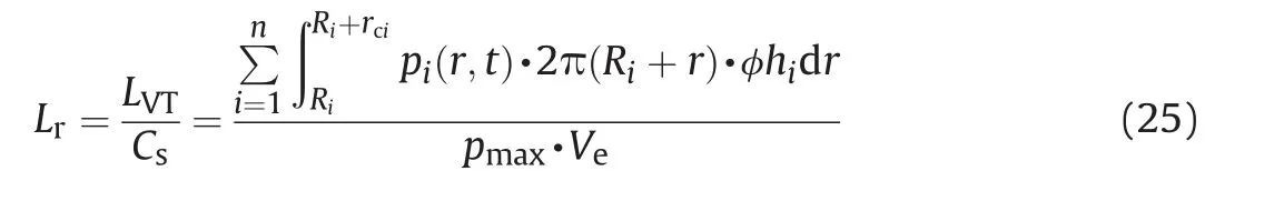
where Lrdenotes leakage rate.
Substituting the pressure drop(Figs.5 and 6),the leakage range(Fig. 7) and the calculation parameters (Table 1) into Eq. (25), the leakage rate of the gas storage salt cavern is obtained (Fig. 9). The gas leakage rate of gas storage also has a power function relationship with the operating time,which is similar to the variation of the gas leakage range. Under an operating pressure of 12 MPa, the leakage rate(the percentage of the total leakage volume of this salt cave gas storage to the storage capacity)of the selected gas storage salt cavern for 1,10,15, 20, 25 and 30 years is 0.51%,1.63%,1.89%,2.01%,2.24%and 3.61%,respectively.Fig.10 shows that although the total thickness of rock salts is 11 times that of interlayers,the total leakage volume of gas in interlayers is approximately 2 times that in rock salt owing to the influence of the leakage range.Therefore,for a bedded gas storage salt cavern,the sealing performance of the interlayers often determines the overall tightness of the storage.
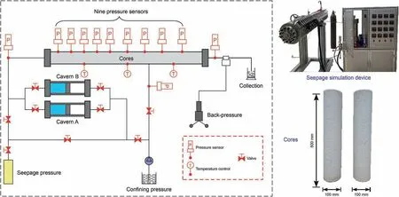
Fig.11. Structural schematic and physical diagram of seepage simulation device.
3.4. Model validation
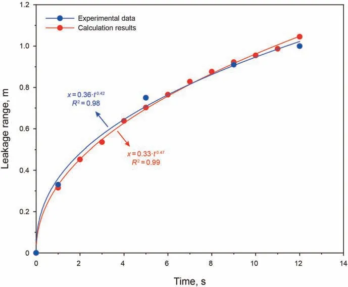
Fig.12. Experimental data and theoretical calculation results of a seepage simulation test.
To confirm the validity of the leakage analysis model of bedded gas storage salt cavern, it is necessary to verify the reliability and accuracy of the calculation results, such as the pressure drop and leakage range. For this purpose, a seepage simulation experiment was carried out using a seepage simulation device, as shown in Fig.11.This seepage simulation device has eleven pressure sensors and three temperature controllers,and has a length of 1.5 m and a diameter of 0.1 m. The cores used in this experiment are two long cores with a length of 0.5 m and a diameter of 0.1 m, hence a combined length of 1.0 m.In order to guarantee the homogeneity of the core, the cores used in this seepage simulation test are compressed synthetic salt rocks.Hence, the lithology and physical and mechanical parameters are not significantly different.The end face of the cores was polished by sandpaper and was wrapped by rubber sleeves to ensure the flatness and connection.In order to avoid the uneven seepage pressure at the joint, the pressure sensors were arranged to avoid the interface,so as to ensure the accuracy of data collection. The seepage medium is nitrogen, and the temperature and confining pressure are 328.15 K and 18 MPa,respectively.
Fig. 12 shows the results of the leakage range obtained from theoretical calculation and from seepage simulation tests. The red and blue data points represent the experimental and theoretical results, respectively. When the injection pressure of nitrogen is 0.45 MPa,the experimental and theoretical results indicate that the time required to penetrate the cores is about 12 and 11.2 s,with an error of 6.7%.Therefore,the theoretical model of leakage analysis of bedded gas storage salt cavern has good applicability and accuracy,and is in good agreement with the experimental results. Although the theoretical equation of gas seepage in deep formation surrounding the gas storage salt cavern is derived in this paper, it is also applicable to the case of Darcy's law, as long as the threshold pressure gradient λ is equal to zero.
4. Application to actual gas storage salt cavern
The tightness evaluation of gas storage salt cavern is a comprehensive safety problem that covers multiple aspects and stages. It not only includes the evaluation of formation tightness,sealing ability of cap rock, wellbore integrity and surface facilities,but also involves several stages such as leaching, operating(working)and closing,which leads to a large number of evaluation indexes for tightness evaluation. In the early site selection and leaching stage,the tightness evaluation of a cavern storage mainly includes some qualitative evaluation indexes such as strata continuity, reservoir depth, regional stability, hydrogeological characteristics and cover sealing.(Canadian-Standards-Association,2014).In the closing stage, the operating pressure of the salt cavern is relatively stable, and it is not easy to fluctuate compared with the operating stage.
There have been few studies on the tightness evaluation of cavern storage in the operating and closing stage.On the one hand,it is difficult to obtain the quantitative evaluation indexes because of the high operating pressure and deep formations; on the other hand, there are many types and causes of leakage, which makes it difficult to quantitatively evaluate the tightness. For this purpose,based on the engineering geological conditions,operating pressure,operating time and leakage type, combined with the above theoretical and numerical calculation results, two quantitative evaluation indexes of leakage range and leakage rate are proposed. The reference values and suggested value are detailed below.
4.1. Maximum admissible leakage range
To avoid gas leakage and connection accident to adjacent salt caverns,some key design parameters need to be considered during the design and construction of an underground gas storage salt cavern,such as pillar width (Wp),distance from faults(Wf), height of open hole (Ht) and thickness of the salt roof (Hs). As shown in Fig.13,the pillar width is the shortest horizontal distance between the two adjacent storage caverns.Distance from faults refers to the distance between the cavern and wellbore and any nearby fault system. The height of the open hole is an important measure to eliminate or limit the impact of creep shrinkage of the salt cavern on wellbore integrity.The thickness of the salt roof is mainly set to prevent cap rock breakthrough due to the high operating pressure.The setting of these parameters is based on the principle of ensuring the tightness and safety of the storage.
The technical safety specification of salt cavern underground gas storage in China stipulates that the distance between the cavern and fault system should be more than 2.5 times the diameter of the salt cavern (National-Energy-Administration-of-China, 2011),hence the leakage range of gas in formations cannot exceed the distance from faults (Wf).

where rc,Wfand D are the leakage range,distance from faults and the diameter of the salt cavern, respectively.
The pillar width is a safety distance set to prevent the adjacent gas storages from being connected due to the gas leakage, and its value depends on the size of the cavern diameter.

where Wp,D and ϖ are the pillar width,diameter of the salt cavern and safety factor, respectively.
Generally speaking, the safety factor ϖ of pillar width of salt dome cavern storage is approximately 1.5-3.0,and that of bedded storage salt cavern is approximately 2.0-4.0 (Wang et al., 2015b,2015c;Zhang et al.,2021).In special and extreme situations such as when the gas storage salt cavern encounters a weak interlayer or remains at the lowest operating pressure for a long time(requiring a large gas supply) or is used as the strategic reservoir, it is recommended that the maximum safety pillar width can be increased to five times the diameter of the salt cavern. Because the stability and tightness of the pillar are not easily guaranteed at this time,engineering accidents have been encountered in Jintan, Jiangsu,China gas storage salt cavern (Li et al., 2019; Yin et al., 2020). In principle,the maximum admissible leakage range cannot reach the salt boundary,faults or adjacent caverns,hence its value should be controlled within the pillar width (Wp), distance from faults (Wf),height of the open hole(Ht)and thickness of the salt roof(Hs).The difference is that the thickness of the salt roof is the reference of the gas leakage range in rock salt, while the pillar width and the distance from faults are the references of the gas leakage range in interlayers. The relational expression can be defined in the following form:
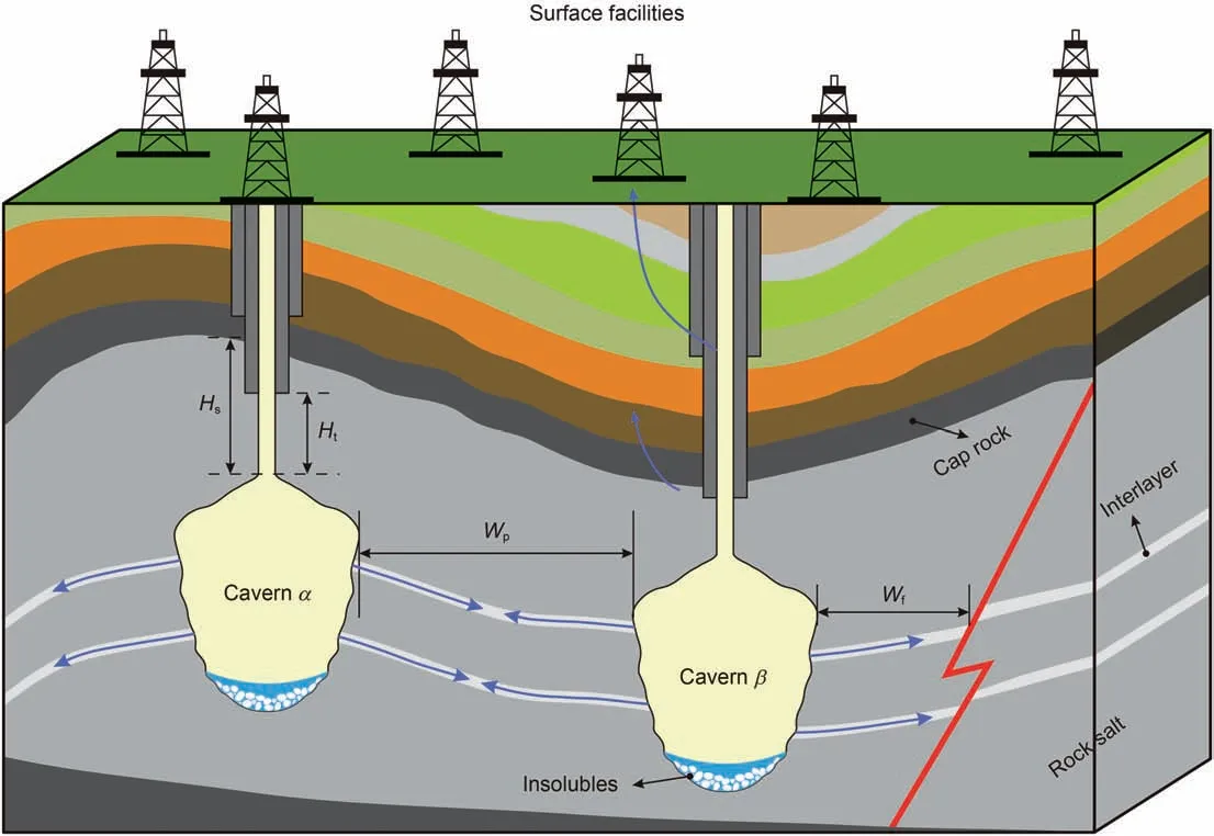
Fig. 13. Key design parameters that affect salt cavern tightness, Wp, Wf, Ht, and Hs are the pillar width, distance from faults, height of open hole and thickness of salt roof,respectively.
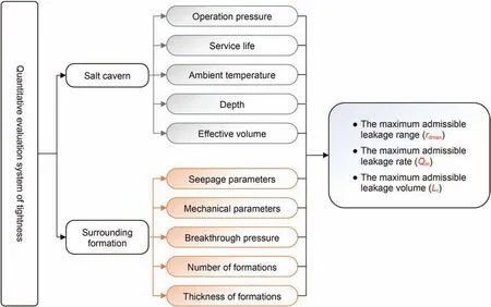
Fig.14. Quantitative evaluation system of tightness of bedded gas storage salt cavern during operating stage.

where rcidenotes gas leakage range in different formations.
4.2. Maximum admissible leakage rate
There is no unified regulation on the maximum admissible leakage rate of gas storage salt cavern in the current specifications and engineering, because the maximum admissible leakage velocity varies with the size, depth and type of storage caverns. In general, the smaller the storage capacity of the salt cavern, the lower the admissible leakage velocity, and the larger the storage capacity of the salt cavern, the greater the admissible leakage velocity. The leakage velocity is an important evaluation index for evaluating leakage risk in a gas storage salt cavern.
The evaluation of the gas leakage rate can refer to the requirements of a nitrogen leak test (NLT), a common tightness test method in oil-gas well engineering (Belgian-Standards, 1998;B′erest et al., 2002). Judgement criterion 1 of the NLT is that the leakage rate gradually decreases with time,and eventually reaches a stable value. However, the NLT does not provide a specific value for the maximum admissible leakage rate. Crotogino (1995)mentioned the minimum detectable leakage rate and the maximum admissible leakage rate using the NLT method at the Solution Mining Research Institute. He suggested that when the operating pressure and temperature were 17 MPa and 300 K, the maximum admissible leakage velocity was approximately 150 kg/day or 270 m3/a. Thiel (1993) has a similar proposal that the maximum allowable leakage velocity of gas storage salt cavern was 160 m3/a.It can be seen that the maximum allowable leakage rate of a gas storage salt cavern is related to the operating pressure,ambient temperature,storage capacity and formations,and there is currently no specific value.
Gas leakage risk evaluation and prediction are long processes,and the maximum admissible leakage varies under different operating stages. There are some limitations in using absolute leakage indicators to evaluate the tightness of a salt cavern,which cannot fully reflect the leakage situation, especially the leakage causes and types. The definition of the gas leakage rate of gas storage salt cavern in this study is different from that of Thiel(1993)and Crotogino (1995). It is defined as the percentage of the total leakage volume of a salt cave gas storage relative to the storage capacity(in Section 3.3),which is a relative quantity rather than an absolute quantity.
This definition not only considers the size of the storage capacity, but also analyzes the influence of operating pressure,ambient temperature and other factors on the leakage rate,which has a good significance for the tightness evaluation of gas storage salt cavern. Based on the calculation results and trends of the gas leakage rate (Fig. 9), it is recommended that the total gas leakage volume of the gas storage salt cavern within the service life cycle should not exceed 5%of the storage capacity.As time increases,the leakage rate gradually increases and eventually stabilizes, but it does not exceed 5% in the end. In addition, when the operating pressure and temperature are 12 MPa and 328.15 K, the average annual leakage velocity is approximately 253.35 m3/a, which is in good agreement with the recommended values of Crotogino(1995)and Thiel (1993). The conversion equation between the leakage velocity and leakage rate of gas storage salt cavern is as follows:
4.3. Quantitative evaluation system of tightness
According to the above-mentioned research contents and results,the tightness evaluation of gas storage salt cavern during the operating stage can be divided into two parts: salt cavern and surrounding formations. As shown in Fig. 14, the factors of salt cavern influencing the tightness mainly include: operating pressure(pin),service life(Tlc),ambient temperature(Tc),depth(Hc)and effective volume (Ve). The factors of surrounding formations influencing the tightness mainly include: seepage parameters(permeability and porosity),breakthrough pressure(pb),number of formations (n), thickness of formations (hi). All the influencing factors listed in Fig.14 are related to the leakage range (in Section 3.2), leakage rate (in Section 3.3) and leakage volume (in Section 3.3), which are also the key quantitative indexes for tightness evaluation during salt cavern operation.
5. Conclusions
(1) One-dimensional and plane radial gas seepage governing equations in deep formations surrounding underground storage salt caverns have been derived and solved by theoretical and numerical methods. The gas seepage governing equation in this type of deep formation is different from Darcy's law. The effects of gas slippage, threshold pressure gradient in the formation must be considered. These governing equations can also be used for seepage analysis in other deep underground engineering facilities, such as geological sequestration of carbon dioxide, oil and gas extraction.
(2) As the seepage distance increased, the seepage pressure in the formations decreased sharply during the early stage,and then decreased gently until the flow stopped. Because the seepage parameters of rock salt are lower than those of interlayers, the pressure drop of gas in the rock salt is more severe. The leakage range of gas in formations surrounding the salt cavern has a positive power function relationship with the operating time. When the operating pressure and service time are 12 MPa and 30 years,the maximum leakage range of gas in the selected salt cavern under the plane radial flow is approximately 69.00 m, which is within the safety permission range stipulated in the safety technical specification of salt cavern underground gas storage in China.
(3) A seepage simulation experiment was carried out using selfdeveloped seepage test equipment to verify the reliability and applicability of the built model. The comparison results show that the theoretical calculation results are highly consistent with the experimental data of the seepage simulation, and the calculation error of the seepage range was approximately 6.70%. Therefore, the leakage analysis model and seepage governing equation can accurately reflect the gas seepage in formations surrounding the bedded gas storage salt cavern, which has guiding significance and application value in actual engineering.
(4) Based on the theoretical analysis and calculation results of the pressure drop and leakage range, a new quantitative index named leakage rate was defined for salt cavern tightness evaluation.The leakage rate in this study was defined as the percentage of the total leakage volume of gas to the storage capacity,which is a relative quantity that can reflect the gas leakage degree regardless of the influence of the size of the cavern storage.Under an operating pressure of 12 MPa,the leakage rate of the selected salt cavern for 1,10,20 and 30 years was 0.51%,1.63%, 2.01% and 3.61%, respectively.
Acknowledgements
The authors wish to acknowledge the financial supports from Jiangxi Provincial Natural Science Foundation (Grant No.20212BAB214009, 20212BAB214014), the National Natural Science Foundation of China (Grant No. 51874273), the Key Science and Technology Research Project in Jiangxi Province Department of Education (Grant No. GJJ200634, GJJ200637), the Open Project of State Key Laboratory of Geomechanics and Geotechnical Engineering,Institute of Rock and Soil Mechanics,Chinese Academy of Sciences(Grant No.Z020016).The authors are sincerely grateful to Jaak J Daemen, Mackay School of Earth Sciences and Engineering,University of Nevada,for his thoughtful proofreading of this paper.
杂志排行
Petroleum Science的其它文章
- A fast space-time-domain Gaussian beam migration approach using the dominant frequency approximation
- Predicting gas-bearing distribution using DNN based on multicomponent seismic data: Quality evaluation using structural and fracture factors
- Reflection-based traveltime and waveform inversion with secondorder optimization
- Determination of dynamic capillary effect on two-phase flow in porous media: A perspective from various methods
- Settling behavior of spherical particles in eccentric annulus filled with viscous inelastic fluid
- Laboratory investigation on hydraulic fracture propagation in sandstone-mudstone-shale layers