Quantitative investigation of multi-fracture morphology during TPDF through true tri-axial fracturing experiments and CT scanning
2022-09-23MingHuiLiFuJianZhouJinJunLiuLiShanYuanGuoPengHuangBoWang
Ming-Hui Li , Fu-Jian Zhou , Jin-Jun Liu , Li-Shan Yuan , Guo-Peng Huang ,Bo Wang e,**
a State Key Laboratory of Petroleum Resources and Prospecting, China University of Petroleum-Beijing, Beijing,102249, China
b Unconventional Oil and Gas Research Institute, China University of Petroleum-Beijing, Beijing,102249, China
c Institute of Photonics, Leibniz Universitat Hannover, Hannover, 30167, Germany
d Development Company, PetroChina Xinjiang Oilfield Company, Karamay, 834000, Xinjiang, China
e Petroleum College, China University of Petroleum-Beijing, Karamay, Xinjiang, 834000, China
Keywords:Hydraulic fracturing Temporary plugging and diverting fracturing (TPDF)Multiple fracture Tri-axial experiment CT scanning
ABSTRACT Due to the reservoir heterogeneity and the stress shadow effect, multiple hydraulic fractures within one fracturing segment cannot be initiated simultaneously and propagate evenly, which will cause a low effectiveness of reservoir stimulation.Temporary plugging and diverting fracturing (TPDF) is considered to be a potential uniform-stimulation method for creating multiple fractures simultaneously in the oilfield.However,the multi-fracture propagation morphology during TPDF is not clear now.The purpose of this study is to quantitatively investigate the multi-fracture propagation morphology during TPDF through true tri-axial fracturing experiments and CT scanning. Critical parameters such as fracture spacing, number of perforation clusters, the viscosity of fracturing fluid, and the in-situ stress have been investigated.The fracture geometry before and after diversion have been quantitively analyzed based on the two-dimensional CT slices and three-dimensional reconstruction method. The main conclusions are as follows: (1) When injecting the high viscosity fluid or perforating at the location with low in-situ stress, multiple hydraulic fractures would simultaneously propagate. Otherwise, only one hydraulic fracture was created during the initial fracturing stage (IFS) for most tests. (2) The perforation cluster effectiveness (PCE) has increased from 26.62% during the IFS to 88.86% after using diverters. (3) The diverted fracture volume has no apparent correlation with the pressure peak and peak frequency during the diversion fracturing stage (DFS) but is positively correlated with water-work. (4) Four types of plugging behavior in shale could be controlled by adjusting the diverter recipe and diverter injection time, and the plugging behavior includes plugging the natural fracture in the wellbore, plugging the previous hydraulic fractures, plugging the fracture tip and plugging the bedding.
1. Introduction
Horizontal well with multi-cluster fracturing technology has become a widely applicable stimulation technology for unconventional resources,such as tight oil and shale gas(Daneshy,2011;Liu and Reynolds, 2021). The key to this technology is to create multiple transverse fractures by injecting high-pressure fracturing fluid,which could significantly improve the contact area in the pay zone (Wang et al., 2020a, 2020b). To reduce the cost and increase production capacity,the standard operation is to perforate multiple clusters in one fracturing segment and thus make multiple fractures propagate simultaneously (Carpenter, 2018; Murphree et al.,2020; Weddle et al., 2018). However, recent advanced downhole monitoring data has shown that multiple fractures often fail to propagate uniformly and sometimes even fail to initiate (Miller et al., 2011; Wheaton et al., 2014, 2016). The production logging data from Miller's work showed that about one-third of perforation clusters were invalid for production, and another one-third contributed to about two-thirds of production (Miller et al., 2011).Spain et al. (2015) also pointed out that 40%-60% of perforation clusters contributed little or almost no productivity in unconventional reservoirs(Spain et al.,2015).In addition,many results from distributed acoustic senor (DAS) and distributed temperature sensor (DTS) showed that only a few prominent fractures existed when perforating multiple clusters in a fracturing segment(Gurjao et al., 2021; Ramurthy et al., 2016; Somanchi et al., 2016; Ugueto et al.,2016).
To study the simultaneous propagation mechanism of multifracture, scholars have carried out many true tri-axial fracturing physical experiments (one kind of indoor hydraulic fracturing approach)(Zhang et al.,2022).El Rabaa(1989)studied the multiple fracture propagation in the vertical wells with different welldeviation angles using gypsum samples. Their results showed that high deviation angles and close fracture spacing would cause multiple fractures to be merged, resulting in only one primary fracture in the formation (El Rabaa, 1989). Subsequently, Crosby(1999) conducted indoor fracturing experiments using cement samples with two perforation clusters,while these two perforation clusters were injected respectively by one shared injection system and two different injection systems.Their results showed that one shared injection system limited the initiation ability of subsequent fractures. Two hydraulic fractures could be initiated using two different injection systems, but the peak pressure of subsequent fractures was 14% higher than that of the initial fracture (Crosby,1999). Alabbad (2014) also conducted a series of multi-fracture propagation experiments using gypsum samples, and their results showed the outer fractures preferentially propagated while the internal fractures were challenging to initiate (Alabbad, 2014).Michael (2016) used the solidified gelatin samples to conduct the visualization fracturing experiment of three clusters in one fracturing segment. Their results showed that at least half of all experiments had only one fracture (Michael, 2016). The above experimental results showed a significant challenge for creating multiple fractures simultaneously in one fracturing segment. In general, the first initiation point usually corresponds to the rock with the lowest stress or the weakest strength both in the laboratory and at the oilfield site. Once the initial hydraulic fracture is created, the injection pressure will decrease to a lower fracture propagation pressure. Meanwhile, the net pressure within the initial fracture would create induced stress,which will make other fractures difficult to initiate in the nearby formation. Hence, the fracturing fluid in the wellbore prefers to flow into the initial fracture and the subsequent fractures cannot be initiated from the un-stimulated perforation clusters due to its higher breakdown pressure. Therefore, how to divert the fracturing fluid into the subsequent fractures and meanwhile create higher injection pressure in the wellbore is the key to promoting subsequent fracture initiation and propagation.
Temporary plugging and diverting fracturing technology(TPDF)is considered the most promising method to promote the initiation and propagation of subsequent fractures in the oilfield(Wang et al.,2020).In this technology,one diversion fracturing stage(DFS)will be added after the initial fracturing stage (IFS), in which the fracturing fluid with self-degradable diverters (fibers, particles or powders) will bridge and plug within the opened fractures or the perforation clusters, thereby increasing the injection pressure and diverting the fracturing fluids to the subsequent fractures (Wang et al., 2015). At present, some scholars have verified the feasibility of artificial plugging in creating diverted fractures in different scenarios based on true tri-axial fracturing experiments. Wang et al. (2015) studied the plugging and diversion mechanism in the near-wellbore plane in the vertical well. Through the direct observation of the rock surfaces, they verified that a diverted fracture could be formed in the vertical well plane after injecting diverters when the horizontal principal stress difference was less than 7.5 MPa,and the diverted angle was negatively correlated with the stress difference(Wang et al.,2015).Subsequently,Xiong et al.(2018)used the ultra-large sandstone rock sample with the size of 762 mm × 762 mm × 914 mm, and they observed that a new diverted fracture was produced in different layers after diversion(Xiong et al., 2018). Mou et al. (2018) designed a new multi-stage tri-axial fracturing system and studied the feasibility of multistage temporary plugging fracturing in carbonate rocks. In their experiments,the injection pressure rapidly increased and then the new diverted fractures were created in different sections along the horizontal wellbore (Mou et al., 2018). Wang et al. (2020) verified the feasibility of producing a complex fracture network in tight sandstone by injecting fibers and powders. Their experimental results showed that the complex fracture network had been created after multiple diversions (Wang et al., 2020).
These above studies confirmed the possibility of diverted fractures formed in different field scenarios,but these works have some limitations:firstly,most samples were sandstone or limestone with good homogeneity, which cannot truly reflect the complex geological characteristics of unconventional reservoirs, such as natural fractures or bedding (Liu and Forouzanfar, 2018). As far as the author's knowledge, there are few studies of multiple fracture propagation using shale samples during TPDF. Secondly, in their experiments,methods of splitting the samples or directly observing rock surfaces were applied to identify the initial or diverted fractures. Such methods cannot observe the fracture morphology inside the sample,and sometimes this observation is accidental.Zou et al., (2016) and Guo et al. (2021) have innovatively applied the computerized tomography (CT) scanning technique to reveal the real fracture geometry in laboratory fracturing.Unfortunately they focused on fracture geometry in the initial fracturing stage and have not considered the diverted fracture geometry after the diversion stage(Zou et al.,2016;Guo et al.,2021).Thirdly,as far as the authors' knowledge, the initial fracture geometry and the diverted fracture geometry during TDPF have not been investigated quantitatively through CT scanning yet. The further relationship between pressure response and the diverted fracture volume have not been revealed clearly.
To overcome the above shortcomings, this study quantitatively investigated the multi-fracture morphology during TDPF based on true tri-axial fracturing experiments and CT scanning. Critical factors of in-situ stress,the number of fractures,fracture spacing,and fracturing fluid viscosity were investigated. At the same time, to identify the initial fracture and diverted fracture morphology more clearly,all the samples were scanned entirely by CT after the initial and diversion fracturing stages. After that, these two-dimensional(2D) CT slices would be reconstructed to three-dimensional (3D)fracture to obtain the fracture volume information.The relationship between diverted fracture volume and pressure response will be further revealed.
2. Experimental samples and equipment
2.1. Sample preparation
Longmaxi shale outcrops(Fig.1)were obtained through a series of works including the geological survey,geological measurements,field development and sample preparation in Changning, Sichuan Province, China. Samples were cut into cubes with the size of 300 × 300 × 300 mm3, and they were further processed to 100 × 100 × 100 mm3cubes to facilitate the overall CT scan, so these samples have similar mechanical properties.Six groups of triaxial compression tests were used to determine their Young's modulus and Poisson's ratio in different core directions, and two groups of Brazilian compression tests were used to determine the tensile strength. When the core was taken vertically and the confining stress is zero, samples have a Young's modulus of 38.22 GPa,a Poisson's ratio of 0.141,and average tensile strength of 7.51 MPa. The detailed measured parameters in different core directions and confining stresses are shown in Tables 1 and 2.

Fig.1. Longmaxi shale outcrops in Changning,China(Upper pictures show the cutting process of cubic samples; bottom pictures show the standard cylindrical samples after rock mechanics test).
As shown in Fig. 2, the horizontal wellbore was drilled in the center of the rock samples, and the wellbore has a diameter of 16 mm and a length of 70 mm. A series of slots were processed through the circular metal piece to simulate the initial damage of multiple perforation clusters. Each slot has a depth of 3 mm and a thickness of 1 mm.High strength epoxy resin was injected into the annulus and then the metal wellbore can be cemented to the wellbore wall. The wellbore has an outer diameter of 12 mm, an inner diameter of 8 mm and a length of 30 mm,and there is a 40-mm open hole section below the wellbore.
2.2. Fracturing fluid and diverters
Three kinds of fracturing fluids (slickwater, viscous slickwater and HPG fracturing fluid) were used during the IFS, respectively.The slickwater was composed of 0.1 wt% DR-800 (a conventional drag reducer),and its viscosity was 10 mPa s.The viscous slickwater has a viscosity of 80 mPa s,which is composed of 0.8 wt%DR-800.To highlight the effect of viscosity, we also used the cross-linked HPG fracturing fluid, and the HPG fracturing fluid was composed of 0.3 wt% JK101, 0.06 wt% citric acid,1 wt% flow-back surfactant,0.1 wt% bactericide, and traces of other additives. The apparent viscosity of the HPG fracturing fluid is 500 mPa s, measured by a rotational viscometer. According to Mou's work(Mou et al., 2018),fibers and powders should have a lower concentration as diverters;otherwise,the tight plug will be formed in the wellbore and unable to enter the fractures (Mou et al., 2018). In our tests,1 wt% fibersand 0.5 wt% 40/70 mesh powders were selected as the diverters(Fig. 3). The average length of fibers is 5 mm, and its diameter is 10 μm. The fibers and powders are both made of a copolymer of lactic acid with glycolic acid. Their density is 1.24 and 1.15 g/cm3,respectively.
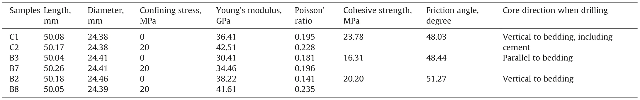
Table 1 Rock mechanical properties.
2.3. True tri-axial fracturing system
As shown in Fig.4,the true tri-axial fracturing system typically includes a true tri-axial confining framework, a confining load pump, an ISCO pump, intermediate containers, data monitoring devices and a heating system. Fig. 4a shows the schematic of the whole system,and Fig.4b shows the physical picture of part of the system. The initial fracturing fluid or the diverting fracturing fluid(with diverters) were put into different intermediate containers and then pumped into the rock samples through the ISCO pump(Teledyne ISCO,Lincoln,Nebraska,USA).In this study,the pipeline diameter is 6 mm, which is enough to ensure diverters flow smoothly into the open hole of the rock sample. Meanwhile, the confining load pump can inject the hydraulic oil into three movableplates to maintain the tri-axial stress in the tri-axial confining framework.The maximum tri-axial stress can reach 30 MPa,and its accuracy is 0.1 MPa. The maximum fluid injection pressure is 70 MPa,and the maximum injection flow rate is 204 mL/min.

Table 2 Rock tensile strength.

Fig. 2. 100 × 100 × 100 mm3 shale samples after processing.
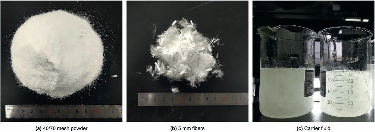
Fig. 3. Diverters and carrier fluid.
2.4. CT scanner
As shown in Fig. 5, Brivo CT385 from GE company was used to observe the internal fracture morphology of rock samples after the IFS and the DFS. This scanner mainly includes an X-Ray source, a detector, a scanner framework, and an imaging system. The maximum output power of the scanner is 28 kW, the maximum scannable voltage and current is 140 kV and 200 mA, respectively.The unit pixel size is 190 μm×190 μm,and the scan thickness of a single slice is 0.625 mm.The cube sample was placed in the middle of the CT frame and scanned by X-Ray CT from one side to the other.Subsequently,the 3D fracture between slices will be reconstructed based on CT scanning data, and the fracture volume will be calculated using commercial software Avizo 2019 through the interactive threshold function.
3. Experimental scheme and process
3.1. Experimental scheme
Based on the previous experiments (Mou et al., 2018; Wang et al., 2015), the injection rate should be designed as 10-90 mL/min(Mou et al.,2018;Wang et al.,2015).Hence,the injection flow rate in this study was designed as 30 mL/min. According to the experimental results from Wang et al. (2015), new diverted fractures would be created when the horizontal stress difference is below 7.5 MPa,so the stress difference was designed below 7.5 MPa.As listed in Table 3,critical parameters investigated include fracture spacing, number of clusters, fracturing fluid viscosity, and in-situ stress. Tests 1-3 explored the influence of fracture spacing. The effect of fluid viscosity was investigated by Tests 4-5. Tests 6-7 explored the effect of the number of fractures.Test 8 explored the influence of the in-situ stress on multiple fracture propagation.Each sample will have one IFS and one DFS. After each stage, the fracture morphology and pressure response would be analyzed in detail.
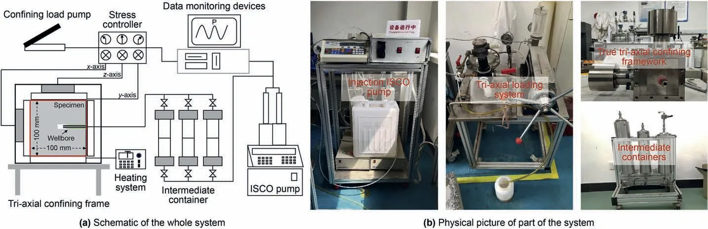
Fig. 4. True tri-axial fracturing system.
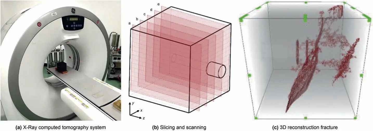
Fig. 5. X-ray computed tomography system and CT data processing.
3.2. Experimental process
The main experimental procedures for tests 1-8 are as follows:a) Prepare the experimental rock samples and working fluids.b) Put the working fluid into the intermediate containers,place the prepared samples in the true tri-axial loading framework, and connect the devices.
c) Load the tri-axial stress according to the in-situ stress conditions. Hydraulic oil is injected into three plates by a triaxial stress loading system to load different stresses in three directions.
d) Inject fracturing fluid through the ISCO pump to create the initial fracture and meanwhile record the real-time injection pressure curve in the initial fracturing stage. Initial fracture has been created when the injection pressure has a sudden drop,and then stop injecting.
e) Unload the tri-axial stress, take out the sample after the initial fracturing,and perform CT scan of the whole sample to obtain the initial fracture morphology.
f) Repeat steps a)-c) for the diversion fracturing stage (DFS).The injection fluid should be changed to the fracturing fluid with diverters in the DFS. When the volume of fracturing fluid reaches a specific value or the diverted fracture is created, stop injecting and record the injection pressure curve.
g) Unload the tri-axial stress,take out the sample after the DFS,and perform CT scanning of the whole sample to obtain the diverted fracture morphology.
h) Collect and analyze injection pressure and fracture volume information.
4. Experimental results and analysis
4.1. Effect of the perforation cluster spacing
The perforation cluster spacing means the distance among multiple perforation clusters along the horizontal wells. Usually,smaller perforation cluster spacing could create more hydraulic fractures and obtain a larger reservoir stimulation volume. However,such small perforation cluster spacing would produce intense induced stress,which would limit the initiation and propagation of adjacent fractures.To study the effect of perforation cluster spacing,tests 1-3 have three perforation clusters with a different fracture spacing of 5, 10, and 15 mm, respectively, but other conditions remain constant.
Figs. 6-8 show the 2D CT scanning slices of Test 1, Test 2 and Test 3 after the IFS and DFS.These CT slices were scanned following the manners in Fig.5b,and here we only show five yz planes with x coordinates of 10, 30, 50, 70, and 90 mm. In Fig. 6a, after the IFS,only one hydraulic fracture was initiated in the toe cluster in Test 1,which propagated perpendicular to the horizontal minimum principal stress and connected a natural fracture near the edge of the sample. After the DFS as shown in Fig. 6b, three transverse fractures were initiated from the slots (two diverted fractures and one initial fracture)and one transverse fracture was initiated from the open hole section. At the same time, two hydraulic fractures near the toe section merged with each other,and the fractures also communicated with the natural fractures, resulting in a complex fracture network.
As shown in Fig.7a,the IF in Test 2 could not be initiated at the perforation cluster position but initiated along the natural fracture in the open hole.Subsequently,the natural fractures were plugged in the DFS, and the three diverted fractures all initiated effectively from the three perforation clusters (Fig. 7b). These two hydraulic fractures near the toe section had an apparent “repulsion” phenomenon due to stress interference, and the shear fractures were created between hydraulic fractures after the DFS, and a complex fracture network can also be observed.
In the IFS of Test 3, as shown in Fig. 8a, one hydraulic fracture was initiated in the middle perforation cluster. After the DFS, the initial fracture opened with a wider aperture due to the high net pressure in the DFS. At the same time, the toe perforation cluster began to initiate, and the fractures were almost parallel to each other (Fig. 8b). No apparent stress interference behavior could be found after the DFS in Test 3.Unlike the samples in Test 1 and Test 2,there was no complex fracture network in Test 3.Due to the larger fracture spacing and weak stress interference,only multiple branch fractures were found within the hydraulic fractures after the DFS.Meanwhile,a larger fracture spacing also induces wide fracture and the heel perforation cluster could not initiate after the DFS.
By comparing 2D CT slices of Tests 1-3 with different fracture spacings,three phenomena can be found:firstly,only one hydraulic fracture was created in IFS whatever the fracture spacing is,and no apparent regularity can be found in the initiation position. Secondly, multiple perforation clusters can simultaneously initiate after DFS, but the propagation behavior of diverted fractures is significantly different due to the fracture spacing.Specifically,when the cluster spacing is close (less than 5 mm in our tests), the subsequent DFs will merge rapidly with the previous IF. With the increase in the fracture spacing (5-10 mm in our tests), the subsequent diverted fractures will propagate with curvature due to the intense stress shadow effects. When the fracture spacing increases to a specific value (15 mm in our tests), the subsequent diverted fractures propagate nearly parallelly because of the weak induced stress. Finally, the complexity of the fracture network is higher with smaller fracture spacing after the DFS. The reason is that more shear fractures between hydraulic fractures can be generated among close-spaced fractures, while only a few bifurcated fractures are generated among loosely spaced fractures.
4.2. Effect of the fracturing fluid viscosity
The fluid viscosity is a critical evaluation index of the fracturingfluid performance. Usually, the fracturing fluid with low viscosity can produce lower friction, while the fracturing fluid with high viscosity can produce more friction. In addition, high-viscosity fluids can better carry proppants or diverters. In this section,compared with the low-viscosity slickwater of Test 2 (10 mPa s),Tests 4-5 were simulated using viscous slickwater(80 mPa s)and cross-linked HPG fracturing fluid(500 mPa s), respectively.
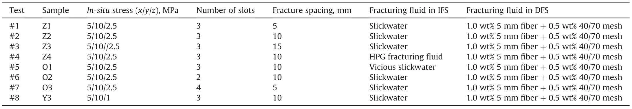
Table 3 Experimental scheme in Tests 1-8.

Fig. 6. CT scanning after IFS and DFS in Test 1 (IF: initial fracture generated in IFS; DF: diverted fracture generated in DFS.).
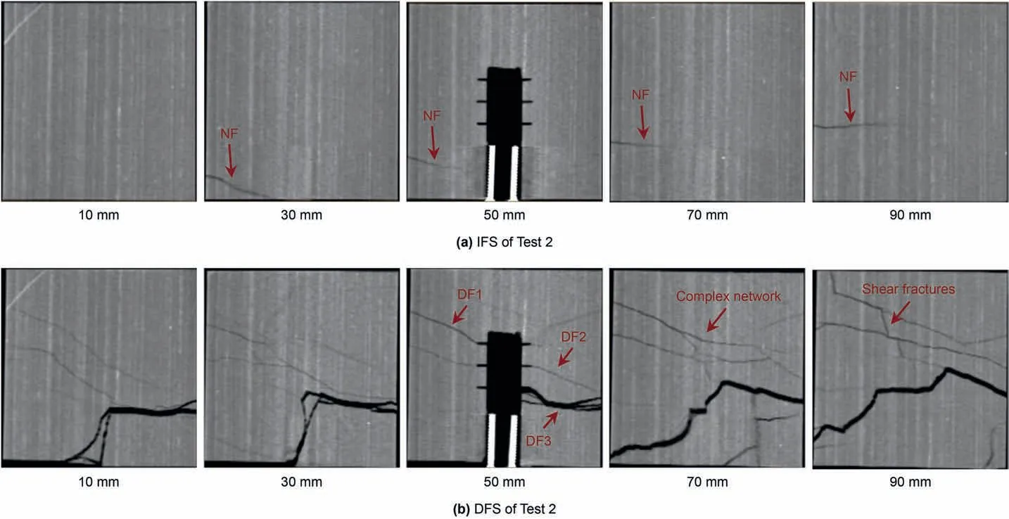
Fig. 7. CT scanning after IFS and DFS in Test 2.
Fig. 9 shows the injection pressure curves using injection fluid with different viscosity.Test 4 and Test 5 both had a pressure peak in the IFS and have multiple pressure peaks in the DFS.As measured above, the tensile strength of Longmaxi shale has an average of 7.51 MPa,the breakdown pressure approximately equals the sum of the tensile strength and the minimum principal stress(2.50 MPa).In addition,the peak pressure(10.02 MPa)in the IFS of slickwater in Test 5 was lower than that (13.33 MPa) of cross-linked HPG fracturing fluid in Test 4.Moreover,its propagation pressure(3.39 MPa)in Test 5 was also lower than that in Test 4 (6.59 MPa) due to the greater friction of the cross-linked HPG fracturing fluid.
Fig.10 shows the CT scanning slices in Test 4 using the crosslinked HPG fracturing fluid in the IFS and DFS. In the IFS, only two hydraulic fractures were created simultaneously and located at the heel and toe sections,respectively,in Test 4(Fig.10a).But four slots were effectively initiated after DFS, and among these four fractures, two initial fractures created in the IFS had a wider aperture, while the two diverted fractures created in the DFS had a narrower aperture (Fig. 10b). Meanwhile, when using the highviscosity fracturing fluid, the complex fracture network was created far-field after DFS.
As shown in Fig.11a,when using the viscous slickwater in Test 5,only one hydraulic fracture was created in the toe perforation cluster and activated the natural fracture far-field in IFS.After DFS,the width of the initial fracture increased obviously, and the remaining two perforation clusters could also get effective initiation (Fig.11b). At the same time, branch and shear fractures were also found in the far-field, but the fracture network complexity of low-viscosity was simpler than that of high-viscosity fluid due to a lower injection pressure in DFS. In addition, stepped fractures appeared due to the influence of bedding.
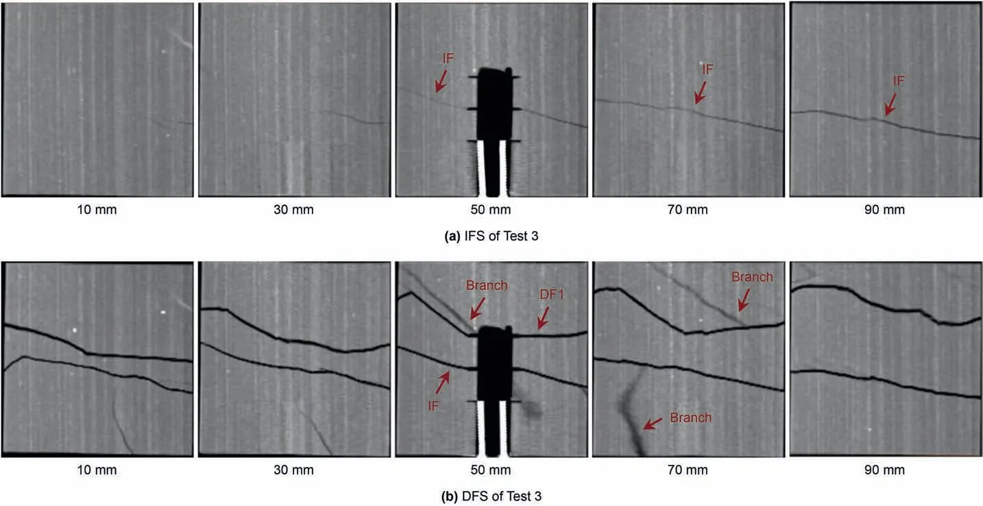
Fig. 8. CT scanning after IFS and DFS in Test 3.
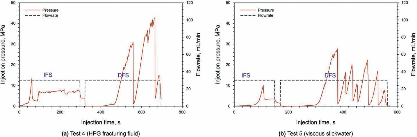
Fig. 9. Injection pressure under different fluid viscosity (Tests 4-5).
The influence of fracturing fluid viscosity mainly lies in the injection pressure and fracture morphology.Firstly,the results of the pressure curve showed that the peak injection pressure and propagation pressure of the high viscosity fracturing fluid were higher in IFS, which will simultaneously create two fractures at the side position. However, when using low-viscosity fracturing fluid, the peak injection pressure and propagation pressure were low,which would create only one fracture in IFS. Secondly, whatever the fracture fluid viscosity is,all perforation clusters in the wellbore can be initiated after DFS in our tests. Moreover,the complexity of the fracture network of the sample using high-viscosity fracturing fluid was higher than that of the sample using the low-viscosity fracturing fluid.This phenomenon mainly comes from two reasons:(1)More natural fractures were activated due to the high fracture net pressure generated by the high-viscosity fluid. (2) The highviscosity fluid can increase the fracture width and have a better performance of carrying the diverters into the fractures. More diverted fractures within the fracture were created after DFS.However,the fracture width formed by the low-viscosity fluid was narrow,and the diverters can only accumulate in the wellbore and cannot form the complex diverted fractures within the fracture.
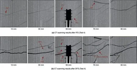
Fig.10. CT scanning after IFS and DFS in Test 4 (The heel perforation cluster was sealed by the epoxy resin).
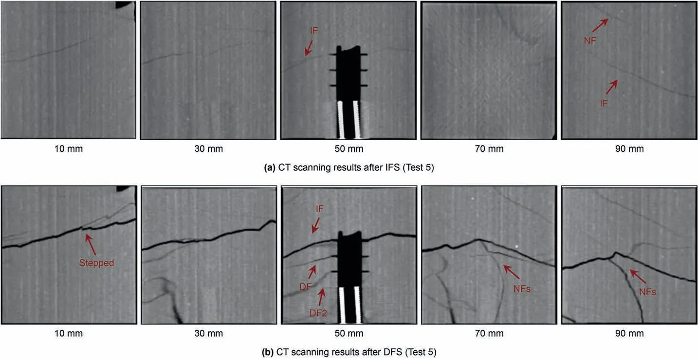
Fig.11. CT scanning after IFS and DFS in Test 5.
4.3. Effect of the number of perforation clusters in fractured formation
To investigate the number of perforation clusters and the natural fracture on the multiple fracture propagation, we built a different number of fractures and fracture spacing in the same stimulation length in Test 6 and Test 7. Test 6 has two perforation clusters with a spacing of 10 mm,while Test 7 has four perforation clusters with a distance of 5 mm.In addition,Test 6 and Test 7 both have one natural fracture cross through the open hole.In Test 6,the natural fracture across the horizontal wellbore is the un-cemented fracture, while the natural fracture in Test 7 is the cemented fracture.Fig.12 shows the injection pressure curves of the two samples.Their pressure fluctuations in the IFS have an obvious difference.Within the un-cemented natural fractures,the pressure was in the“filtration” state, and the pressure slowly increased to the breakthrough pressure and then releases rapidly in Test 6. Within the cemented natural fracture, the injection pressure had a sharp rise and fall, which similar to the common fracturing sample. During the DFS, two samples both have multiple pressure peaks.
Fig.13 shows that the hydraulic fracture in Tests 6 was initiated and propagated along natural fracture during the IFS.As measured through the tri-axial compression tests, the shale samples have a higher Young's modulus (38.22 GPa) and a lower Passion's ratio(0.141). Therefore, the width of the initial natural fracture was so narrow that the CT scanner cannot find its apparent position(Fig. 13a). Meanwhile, the existence of natural fracture decreased the peak pressure in IFS so that no perforation cluster could be initiated.Due to the narrow fracture width,the diverters could only be accumulated in the horizontal wellbore and sealed the natural fracture mouth.Hence,Fig.13b shows that,after DFS,the width of the initial fracture was still narrow, and two hydraulic fractures were initiated from the perforation clusters and one in the open hole section(Fig.13b).In addition,although two hydraulic fractures were both initiated at the near-wellbore after DFS,the fractures still propagated and merged into one primary fracture in the far-field due to natural fractures.
Fig. 14 shows one cemented natural fracture was crossing the open hole in Test 7, and the initial hydraulic fracture was initiated and propagated along it (Fig. 14a). In the IFS, the fracturing fluid could not initiate the four perforation clusters due to the natural fracture.After the DFS,three of four slots had the effective fracture initiations.However,two of these three fractures merged with the primary hydraulic fracture when propagating far-field due to the strong stress interference. In addition, two diverted fractures can also be found in the open hole section(Fig.14b).Compared to Tests 6 and 7,we can find that whether the natural fracture is cemented or not, the hydraulic fractures became one primary fracture farfield after activating the natural fracture.
The injection pressure curve is similar to the common injection curve when the natural fractures are cemented;while the injection pressure curve shows a "filter" feature when the natural fractures are non-cemented.Moreover,hydraulic fractures cannot be created from the perforation clusters no matter how many perforation clusters are.The existence of natural fractures significantly reduces the perforation cluster effectiveness (PCE). After DFS, multiple fractures could be simultaneously created but still merge into a primary fracture far-field due to the natural fractures.
4.4. Effect of in-situ stress
Horizontal stress difference and minimum stress are the main geological parameters controlling the fracture morphology in shale reservoirs.Test 2 and Test 8 have the same completion parameters,but their minimum principal stress was 2.5 and 1 MPa,respectively.As shown in Fig. 10a, Test 2 with high minimum principal stress only created one fracture during the IFS, while Test 8 with low minimum principal stress created multiple fractures simultaneously (Fig. 16a). The pressure curve of Test 8 could reflect that there would be multiple pressure peaks and pressure drops in IFS(Fig. 15). After DFS, multiple parallel diverted fractures could be found in Test 8 with low in-stiu stress. At the same time, the CT scanning showed a highly complex fracture network existed in the near-wellbore, and multiple parallel fractures were formed in the far-field(Fig.16b).Therefore,a low-stress state would promote the generation of multiple fractures from the perforation clusters,and a more complex fracture network would be also created after DFS.
4.5. Analysis of 3D reconstruction fracture volume
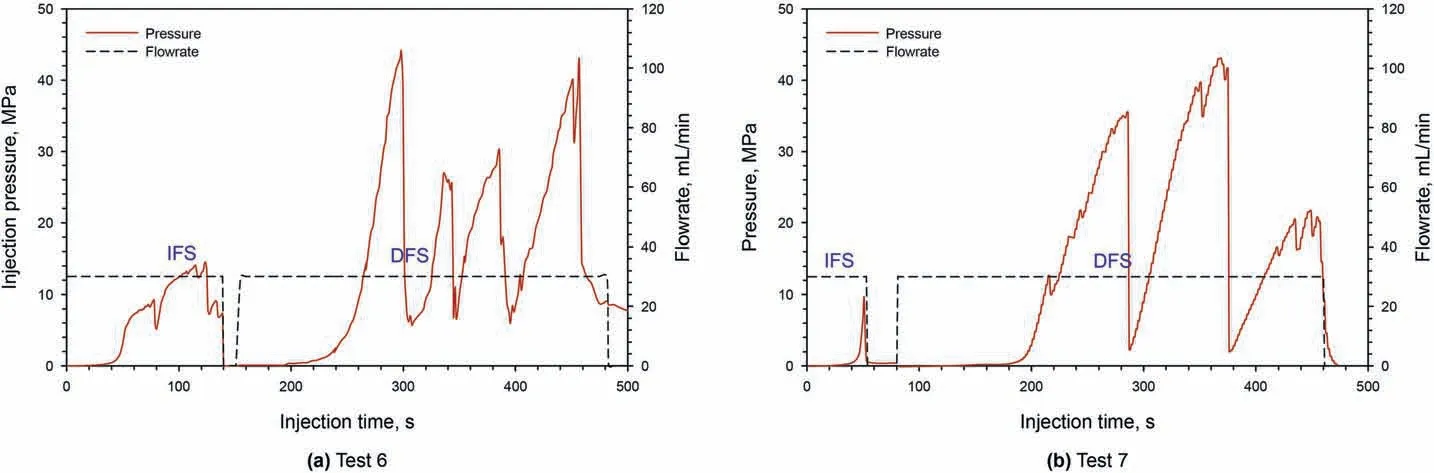
Fig.12. Injection pressure under different numbers of perforation clusters in fractured formation (Test 6 and Test 7).
Two-dimensional CT slices cannot quantitatively determine the fracture volume information in the IFS and DFS. Therefore, 3D reconstruction fractures have been presented using the 3D analysis software Avizo 2019, as shown in Fig.17. According to this figure,one single hydraulic fracture could be created in the six samples in the IFS, and two simultaneous hydraulic fractures in the IFS could be found in the other two samples(Test 4 and Test 8).Meanwhile,the fracture network could be clearly presented due to the interaction behavior between hydraulic fractures with natural fractures or beddings. The volume of the 3D fracture in the eight samples after the IFS ranges from 4632.94 to 28669.27 mm3, and the average fracture volume in the eight samples is 13650.20 mm3.The sample with the least fracture volume is in Test 2, where one natural fracture was created in the open hole. The sample with an enormous fracture volume is in Test 8,where the in-situ stress was lower than other samples and two hydraulic fractures were created simultaneously in IFS.In the subsequent diversion stage,nearly all perforation clusters in eight samples were initiated after the DFS and a complex fracture network including transverse, longitude,and branch fractures can also be found in the 3D images. The volume of the 3D fracture in the eight samples after the DFS ranges from 43712.13 to 115356.2 mm3and its average fracture volume is 64291.03 mm3. Unlike the IFS, the sample with the least fracture volume after the DFS was in Test 6 with only two perforation clusters.Furthermore,the sample with the largest fracture volume after diversion was in Test 8 with a lower in-situ stress.
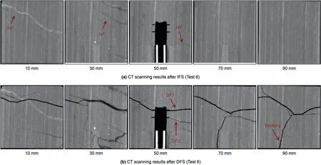
Fig.13. CT scanning after IFS and DFS in Test 6.
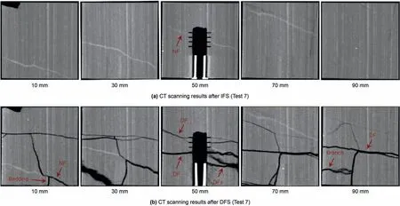
Fig.14. CT scanning after IFS and DFS in Test 7.

Fig.15. Injection pressure curve in Test 8.
Fig. 18 presents the relationship between the fracture volume and the different key parameters. In Fig.18a, the fracture volume has no apparent relationship with the number of the perforation clusters in the IFS. However, the fracture volume constantly increases with the number of perforation clusters in the DFS.Fig.18b shows that the fracture volume becomes less when the fracture spacing increases in the DFS. At present, a similar idea of "close fracture spacing and a big number of fractures” has been also adopted in the field operation.However,in IFS,if multiple clusters of fractures cannot be initiated and propagated at the same time,this strategy seemed not to get the maximum fracture volume from our tests. However, in the DFS, the fracture volume under this strategy would be fully performed.Fig.18c shows that the fracture volume increases with the fracturing fluid viscosity in the IFS and DFS. The results indicate that the carrier fluid with high viscosity can promote a larger fracture volume due to the higher sand/diverters-carrying performance. Fig. 18d shows that the fracture volume will both increase in the initial and diversion stage when the in-situ stress is lower. Hence, the position of the perforation cluster should be selected in the section with lower minimum principal stress.
4.6. Peak pressure and peak frequency vs. fracture volume
Injection pressure is the most intuitive downhole response in the field fracturing operation. During a real fracturing process, the injection pressure is highly influenced by wellbore fluid column pressure, the wellbore friction, perforation friction, and the fluid net pressure. However, the wellbore friction and perforation friction in the laboratory fracturing experiments are so small that the injection pressure could directly reflect the fracture fluid pressure.Hence, the injection pressure usually decreases significantly when one hydraulic fracture is created.The fracture breakdown pressure is considered the peak pressure in the pressure curve, and the occurrence frequency of those pressure peaks is called the peak frequency.Fig.19 counts the peak pressure and peak frequency that occurred in the IFS and DFS of Tests 1-8.As shown in Fig.19a, the peak pressure has a positive correlation relationship with the fracture volume in the IFS, but no obvious correlation relationship with the fracture volume in the DFS.The reason for this difference is that a high peak pressure in the IFS could represent a higher fracture pressure, which could create a larger fracture volume. However, the peak pressure in the DFS could not truly reflect the fracture pressure because the plugging behavior that occurred in the fracture mouth will cause a lower fluid pressure within the fracture than that in the wellbore.In addition,as shown in Fig.19b,the peak frequency in most tests(Tests 1-7)was all one in the IFS,while the peak frequency in Test 8 was four. A higher peak frequency could present a higher fracture volume in the IFS because the peak frequency can represent the interaction between hydraulic fractures and natural fractures in the IFS, which further reflects the possibility of creating complex fractures. In addition, a higher peak frequency makes more micro-fractures and thereby increase the fracture volume in the IFS. However, the peak frequency is weakly positively correlated with the fracture volume in the DFS due to the plugging behavior.Hence,trying to use the peak pressure or peak frequency to evaluate the size of the diverted fracture volume in the DFS seems not available based on our experimental results.
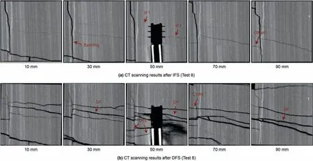
Fig.16. CT scanning after IFS and DFS in Test 8.
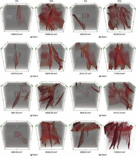
Fig.17. 3D CT reconstruction images and fracture volume of IFS and DFS.
5. Discussion
5.1. Fracture location and perforation cluster effectiveness (PCE)
During the multi-cluster fracturing process, the ratio of the effective perforation cluster to the total perforation clusters is called perforation cluster effectiveness (PCE). The PCE is an important criterion to measure the success of multi-cluster fracturing in field stimulation. Generally, the higher the PCE is, the larger the reservoir stimulated volume is. The above CT scanning slices showed that the initial fracture has three initiation states in IFS: (1) The natural fracture was initiated in the open hole, which caused the perforation cluster ineffective and the PCE is zero. (2)Single fracture was initiated from one perforation cluster, but the initiation position has no apparent regularity. (3) Two fractures simultaneously were initiated from the side position along the horizontal wellbores.In DFS,almost all perforation clusters can get effective initiation. Table 4 further statistics the PCE in the IFS and the DFS. The results show that the PCE in the DFS has increased greatly compared to the PCE in the DFS. Specifically, seven of twenty-six perforation clusters in the IFS were initiated in total,and the average PCE is 26.92%. Twenty-three of twenty-six clusters were initiated in the DFS in total, and the average PCE is 88.46%.Meanwhile, the field data also confirmed our conclusions. For example, Miller's field productivity logging data showed that only one-third of the perforation clusters contribute two-thirds of the productivity (Miller et al., 2011). Ramurthy et al. (2016) indicated that the fractured well with TPDF has more than 80% of fracture initiation effectiveness(Ramurthy et al., 2016).
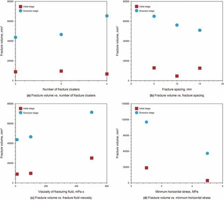
Fig.18. Fracture volume with the different parameters.

Fig.19. Peak pressure and peak frequency vs. fracture volume.
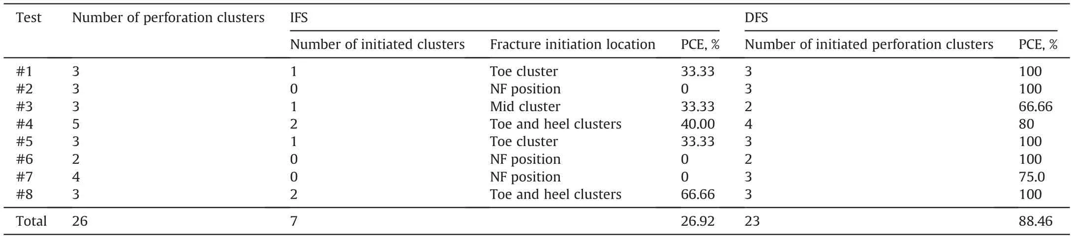
Table 4 PCE in IFS and DFS.
5.2. How to determine the complex fracture volume through injection pressure

Fig. 20. Fracture volume vs. water-work.
Determining the reservoir stimulation volume from the pressure curve is the primary concern of field fracturing diagnosis. In our previous analysis,the peak pressure and peak frequency could reflect the relative size of the fracture volume to a certain extent in IFS, while cannot sufficiently characterize the diverted fracture volume in DFS (Fig. 20). Therefore, to determine the fracture volume in the DFS, we revealed the relationship between waterwork and fracture volume based on the energy-based perspective.The water-work is defined by the product of water horsepower and operation time. In our experiments, the fracturing fluid was injected through the ISCO piston pump,so the calculation equation of water horsepower is different from that in the field method.The water work in the indoor fracturing experiment is defined by the following equations:
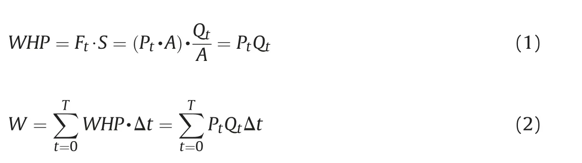
where W is the water-work,J;WHP is the water horsepower,J/s;Ftis the fluid load acting on the piston surface,N;S is the distance of the force Ftacting on the piston surface A,m;Ptis the fluid injection pressure,Pa;Qtis the injection flowrate,m3/s;A is the section area of injection piston surface, m2; Δt is the duration time under pressure Ft; T is the total fracturing time, s.
Fig.20 shows the relationship between water-work and fracture volume in the IFS and the DFS during Tests 1-8.The results showed that there was a significant positive correlation between waterwork and fracture volume. The fracture volume shows a positive linear correlation with the water-work in the IFS. The diverted fracture volume showed a parabolic input relationship with the water-work in DFS, and the correlation coefficient R2is 0.6412.Therefore, on-site operators can calculate the water horsepower and water-work to determine the reservoir stimulation volume in the future. It should be noted that the calculation results of the fracture volume need to be compared with seismic data based on different reservoirs.
5.3. Plugging behavior in shale reservoir and its control methods
The previous 2D CT images and 3D reconstructed fractures showed the fracture morphology after the plugging, but the distribution of the diverters could not be well observed in reality.Four shale samples were spitted to directly observe the distribution of diverters (Tests 1-3 and Test 8) as shown in Fig. 21. In Test 1, the white tight plug formed by the diverters was firstly accumulated in the horizontal wellbore, which effectively plugged the fracture mouth and the fluid flow channel, thus creating the new diverted fractures. Meanwhile, the white diverters were also distributed within the tortuous fracture surfaces,but it was not dense enough to form a diverted fracture within the fractures(Fig.21a).In Test 2,the white diverters firstly plugged the natural cracks with narrow width,as shown in Fig.21b.And then,two diverted fractures were created after the diversion, but the diverters did not distribute on the fracture surface uniformly. Only the diverters near the toe sparsely covered the fracture surface.In Test 3,the dense and tight plug was distributed on the surface of the root fracture,which helps to generate the diverted fracture and create the complex fracture network.In Test 8,the red diverters were injected and the red tight plug was formed both in the wellbore and at the interaction location between the hydraulic fracture and the bedding.
As shown in Fig. 22, the plugging behavior and the diverted fracture morphology can be characterized into four types during TPDF in shale reservoirs:A.plugging natural fractures in the nearwellbore zone to increase the PCE (Fig. 22a). B. plugging the previously opened perforation clusters to promote the initiation of the ineffective perforation clusters (Fig. 22b). C. building a tight plug within the fracture to generate shear fractures and form complex fracture networks (Fig. 22c). D. plugging the entrance of the bedding plane to enlarge the height of the longitudinal fracture(Fig. 22d).
These four types of behavior often occur at random in shale reservoirs. Therefore, selecting and controlling the corresponding temporary plugging behavior is the most concerning issue in the field fracturing design. Here we present a realizable method to control these four types of behavior according to their occurrence conditions.In general,the plugging behavior A and B occurs in the natural or bedding fractures with a small fracture width, but their occurrence time is different according to the fracturing process.The former behavior occurs in the early fracturing period,and the latter occurs in the middle and late fracturing periods.Hence,to achieve plugging behavior A, small diverters (such as fibers or powders)should be injected during the early fracturing period to plug the natural fractures near the wellbore.To achieve plugging behavior C,the small diverters (such as fibers or powders) should be injected during the middle or later fracturing periods. During plugging behavior B,the hydraulic fractures are the prominent fractures with a wide fracture width so the large diverters(such as particles)can be used in the early fracturing period to plug the perforation clusters in the near-wellbore. The plugging behavior D is a composite plugging behavior targeting for different fracture widths,so it requires more complex diverter formulations, such as different types and diverter concentrations of diverters or multiple injection in different fracturing periods. Detailed studies have now been carried out for the plugging formulations under different fracture widths.Zhang et al.(2019)explored the types and formulations of diverters for different fracture widths based on 3D printing models.For example, when the fracture is narrow (<2 mm, natural crack/bedding),fiber and powder are combined.When the fracture width is relatively large (4 mm, primary hydraulic fracture), the combination of particles and fibers should be adopted(Zhang et al.,2019).
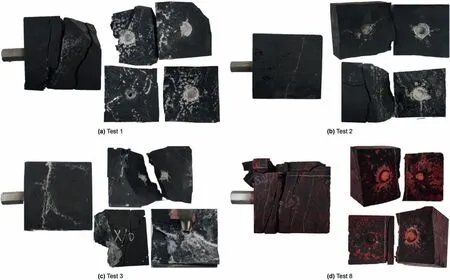
Fig. 21. The fracture geometry after the diversion stage (The white color diverters are used in Tests 1-3; the red color diverters are used in Test 8).
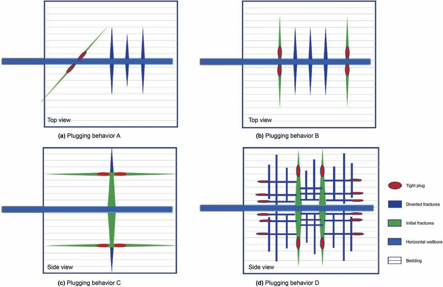
Fig. 22. Four types of plugging behavior observed in shale.
6. Conclusions
A comprehensive and quantitative study of multi-cluster fracturing experiments in horizontal wells was presented during TPDF.Fracture initiation and propagation in the IFS and DFS were studied by true tri-axial fracturing experiments and CT scanning. The effects of fracture spacing,the number of fractures,in-situ stress and fluid injection types on the initiation of multi-cluster fractures are investigated in detail. Based on our experimental results, the following conclusions are drawn:
(1) Natural fractures and stress interference are the main reasons for reducing the PCE during IFS in shale reservoirs,and the PCE can be significantly increased after diversion. The PCE in the IFS is only 26.92%, while it can be improved to 88.86% after the DFS.
(2) Natural fractures and beddings will increase the complexity of the fracture network, but meanwhile the beddings limit the propagation of fracture height.The natural fractures limit the propagation of fractures far-field, which will lead to the merger of multiple hydraulic fractures.
(3) Increasing the viscosity of the injection fluid and selecting perforation clusters in the lower in-situ stress zone can greatly improve the PCE in IFS.
(4) No apparent correlation between the pressure response(peak pressure or peak frequency) and the fracture volume exists in the DFS. Nevertheless, the fracture volume has a positive correlation relationship with the water-work in the DFS.
(5) Four types of temporary plugging behavior in shale are revealed: (a) plugging the natural fracture in the wellbore,(b) plugging the previous hydraulic fractures, (c) plugging the fracture tip and (d) plugging the bedding. These four plugging behavior can be controlled by adjusting the diverter recipe and diverter injection time.
Acknowledgements
Special thanks to the National Natural Science Foundation of China fund (Project number: 52174045 and No. 52104011),Research Foundation of China University of Petroleum-Beijing at Karamay (No. XQZX20210001), PetroChina Innovation Foundation(2020D50070207).
杂志排行

Petroleum Science的其它文章
- A fast space-time-domain Gaussian beam migration approach using the dominant frequency approximation
- Predicting gas-bearing distribution using DNN based on multicomponent seismic data: Quality evaluation using structural and fracture factors
- Reflection-based traveltime and waveform inversion with secondorder optimization
- Determination of dynamic capillary effect on two-phase flow in porous media: A perspective from various methods
- Settling behavior of spherical particles in eccentric annulus filled with viscous inelastic fluid
- Laboratory investigation on hydraulic fracture propagation in sandstone-mudstone-shale layers