Fracture propagation and induced strain response during supercritical CO2 jet fracturing
2022-09-23CnCiBngRunLiYiYoZhngWenHeYingXinYngYongKngJiWeiWu
Cn Ci , Bng-Run Li , Yi-Yo Zhng , Wen He , Ying-Xin Yng ,b, Yong Kng ,Ji-Wei Wu
a School of Mechanical Engineering, Southwest Petroleum University, Chengdu, 610500, Sichuan, P.R. China
b The State Key Laboratory of Oil & Gas Reservoir Geology and Exploitation, Southwest Petroleum University, Chengdu, 610500, Sichuan, P.R. China
c Shu'nan Gas-Mine of Southwest Oil and Gas Field Company, Luzhou, 646000, Sichuan, P.R. China
d Hubei Key Laboratory of Waterjet Theory and New Technology, Wuhan University, Wuhan, 430072, Hubei, P.R. China
e School of Engineering and Applied Sciences and Department of Physics, Harvard University, Cambridge, 02138, United States
f School of Mechanical Engineering, Yangtze University, Jingzhou, 434023, Hubei, P.R. China
Keywords:Supercritical carbon dioxide fracturing Jet fracturing Fracture morphology Strain variation
ABSTRACT To investigate fracture generation and strain variation during SC-CO2 (supercritical carbon dioxide) jet fracturing, the model of induced strain is established and the experiments are comprehensively studied.The influence factors are comprehensively explored,such as jet pressure,ambient pressure,etc.With the increasing jet pressure,the fracture morphology changes from parallel cracks to oblique cracks.Both the mass loss of specimen and CO2 absorption increase significantly,and the growth rate and minimum value of strain also rise exponentially. Under a high ambient pressure of 8.0 MPa, the main fractures mostly propagated from the surface to the bottom surface of the specimen.The maximum strain and the stable duration under higher ambient pressure are 1.5 times and 10 times, respectively, of the case under the ambient pressure of 5.0 MPa.The comparison shows that the optimal jet distance is 5-7 times the nozzle diameter, resulting in massive mass loss, large CO2 absorption, and peak strain. Moreover, the nonlinear variation of strain curve during jet pressurization is related to the type of rock and ambient pressure.These studies clearly show the relationship between the fracture morphology and induced strain,which are crucial for SC-CO2 fracturing in shale gas reservoirs.
1. Introduction
Recently, the non-aqueous fracturing fluid is a promising alternative for shale gas exploitation and development, due to the disadvantages of freshwater fracturing,such as extensive usage,water sensitivity to clay mineral and simple fracture morphology (Zhou et al., 2019; Middleton et al., 2014). As a typical non-aqueous fracturing fluid, supercritical CO2shows a positive result while it is injected into the shale gas reservoir. Many shreds of evidence support that the supercritical CO2fracturing can efficiently reduce water consumption, prevent the swelling of clay mineral and enhance the complexity of fracture network, implementing the goals of both improving fracturing and sequestering CO2in shale reservoirs (Middleton et al., 2014; Wang et al., 2019; Zhou et al.,2019). Therefore, the increasing attention has been paid on the fracture initiation and propagation in the shale gas reservoir, and scholars have carried out numerous studies.
Experiments and numerical simulations show many factors influenced the fracturing performance, such as the SC-CO2(supercritical carbon dioxide) characteristic and shale formation properties.Firstly,the low viscosity and high diffusivity of SC-CO2means that it can easily invade the micropores and micro-cracks in the shale formation, leading to a large amount of the fracture generation and propagation(Wang et al.,2019;S.Li et al.,2019;Liu et al.,2019; Mollaali et al., 2019). Meanwhile, the penetration of SC-CO2results in some reduction in the mechanical strength and generation of micropores and tiny fractures, which is proved by many experimental observations and research (Huang et al., 2018; Jiang et al., 2018; Yin et al., 2017; Ao et al., 2017; Du et al., 2017; Li et al., 2020; Tian et al., 2020). It can be noticed that after being treated with supercritical CO2, the mineral content and specific surface of the shale specimen decreases. The reasons for the mechanical strength loss of shale treated with SC-CO2were revealed by these findings.Based on the above research,it is concluded that the SC-CO2characteristic is one of the most crucial reasons for the breakdown pressure decrease and much tiny fracture generation in shale samples(Zhang et al.,2016;Chen et al.,2019).Secondly,shale property plays a vital role in fracture type and morphology,such as initial fracture and the bedding plane. As we all know, the formation discontinuities in the shale can determine the fracture initiation and propagation (Zhang et al., 2019a; Tang et al., 2019; Xie et al., 2020; Li et al., 2020). According to the results of SC-CO2fracturing (Zhang et al., 2019b, 2019c; Zhao et al., 2018), similar experimental results show that the initiation and generation of fractures are related to the existence of the initial micro-crack in shale rock. Zhang et al. (2019c) found that the existence of shale bedding has a significant influence on both mechanical strength and fracture propagation.There is an apparent decline tendency of breakdown pressure with the increase in shale bedding plane angle in their experiments. Thirdly, the jet rate, injection pressure,perforation angle are the main controlling factors in hydraulic fracturing. Based on the experiments, it can be seen that a higher injection rate can result in high breakdown pressure (Zhang et al.,2019c). Some researchers have realized that the injection pressure and perforation angle significantly affect fracture type and morphology (Chen et al., 2019; Mollaali et al., 2019; Wang et al.,2019). Moreover, the in-situ stress is also a crucial factor affecting the primary fracture propagating and generating even though many fracture branches are initially created by using SC-CO2. Like water-based fracturing,mostly the main fracture propagated along the maximum in-situ stress direction with many increasing fracture branches confirmed in the experiments and simulations (Zhou et al.,2019; Chen et al.,2019).
As a novel fracturing technology,jet fracturing is proposed and widely applied due to its advantages of casing protection,less usage of mechanical packers and the pressurization. (Tian et al., 2016;Cheng et al.,2013;He et al.,2015,2020;Surjaatmadja et al.,1998).Jet perforating is the partial process of the jet fracturing, which reduces the operation and saves much time during fracturing.So jet fracturing is regarded as a promising alternative for shale gas fracturing because of additional pressurization(Cheng et al.,2013;He et al.,2015;Tian et al.,2016)and annular isolation(Sheng et al.,2013). Because the unit perforation is the base unit of in multiple cluster fracturing in a horizontal well.Therefore,many scholars try to explore the fluid field and fracture generation of single perforation. The pressurization of hydro-jet in the perforation can promote the fracture initiation and propagation(McDaniel et al.,2009;Surjaatmadja et al.,1998).Thereby,combining hydro-jet fracturing and SC-CO2fracturing is proposed, but the enhancement mechanism of SC-CO2jet fracturing is still unclear. Similarly, In order to investigate the flow field and pressurization mechanism of SC-CO2jet fracturing,many experiments and simulations have been carried out (Tian et al., 2016; Cai et al., 2018, 2020a; Hu et al., 2017). It is found that the flow field and pressurization process of SC-CO2jet is affected by the jet pressure, jet distance, ambient pressure and jet temperature(Wang et al.,2015;Christen and Rademann,2009;Liu et al., 2015; Seebald, 2014). The pressurization of SC-CO2jet attributed to the conversion of jet kinetic energy could significantly improve the perforation pressure, leading to more easily fracture initiating and propagating compared with general injection fracturing. The study investigated the effect of jetting parameters and inhomogeneous shale rock on the crack distribution and initiation by using the FSI numerical method(Hu et al.,2017).Then,Cai et al.(2018) further explored the fracture type and generation portion along the perforation via direct observation for the organic glass,the main jet factors are studied. It is found that there are three patterns of crack extension directions in the experimental specimens: surface fracture, longitudinal fracture, and transverse fracture, respectively. Based on the above research, a novel method of multi-times SC-CO2jet fracturing is proposed and studied by Cai et al. (2019a). The influence of shale bedding and the relationship between the flow field and induced strain are comprehensively discussed using experimental methods (Cai et al., 2020b, 2020c).
In the previous studying, the strain monitoring for high-water abrasive jet perforating and jet fracturing is proposed and successfully conducted (Cai et al., 2018, 2019a, 2019b, 2020b, 2020c).However, limited by the experimental setup, the relationship between the fracture generation and the strain variation in rock is still unknown.Even though there are so many achievements reporting the strain and stress distribution in the rock using numerical simulation,it lacks experimental verification and studies.Thus,we designed a new setup and testing method to investigate the fracture propagation and induced strain distribution in the artificial specimens. The study of exploring the relationship between the artificial specimen and strain variation firstly helps us to comprehensively and deeply understand the mechanism of SC-CO2jet fracturing.
2. Experimental setup and methodology
2.1. Experimental apparatus and artificial specimen
The experiments are conducted in the SC-CO2jet fracturing system, which is reported in the previous studies (Cai et al., 2018,2019a). As shown in Fig.1, the experimental system consists of a CO2pumping unit,a CO2cooling unit,a CO2heating unit,a SC-CO2jetting and pressure monitoring, temperature monitoring and strain testing unit. The complete operation procedure of pressurizing and heating the CO2fluid to the defined target pressure and temperature values was discussed in elsewhere (Cai et al., 2018,2019a).
Some key operations are highlighted to make sure the experimental reliability and accuracy.Firstly,to avoid the electromagnetic interference for testing sensors, the buffer tank and kettle are connected with the equipment grounding conductor. Secondly,before SC-CO2jetting,the CO2which has the pressure of exceeding 8 MPa and temperature of 60°C, respectively, is stored and prepared in the buffer tank.Then,the pump stops working to prevent the negative effect of dynamical pumping on the dynamical signal testing. Thirdly, during the SC-CO2jet fracturing, the computer controls the air-operated valve and collects the dynamical data of all sensors.Therefore,the above SC-CO2jet fracturing system could be applied for completing the experimental program.
As we all know, the natural shale rock is a heterogeneous material due to the mixing of minerals, the random distribution of micropores and tiny cracks.The existence of heterogeneity in shale makes it difficult to quantitatively study the fracture propagation and strain variation. To address the problems, these artificial specimens were created and prepared for fracturing studies, since the manufactured samples have an isotropous feature that makes it easier to detect random crack creation and strain testing appropriately. Artificial specimens with identical mineral components,such as silica sand,clay,calcite,dolomite,and cement,are moulded and manufactured in reference to the mineral components in the shale.
The detailed proportion of each mineral in the artificial specimen is shown in Table 1, along with the uniaxial compressive strength (UCS), Young's modulus, Poisson's ratio and the material proportion. The mechanical characteristics match those of the target shale sample which have been collected from the outcrop of the Niutitang Shale Formation in Hunan Province, China. Firstly,each component of the minerals is weighted according to the designed proportion (Fig. 2a), and then they are mixed in the pot with 40 wt%water(Fig.2b).After that,the well-mixed mud is then separated into the cylindrical organic mold with a diameter of 100 mm and a height of 100 mm (Fig. 2c). Under curing room maintenance at the temperature of 25°C over 28 days in the laboratory, all the artificial specimens have enough strength. Both ends of the cylindrical samples are ground to ensure obtaining the smooth, flat, parallel surface. Then a deep hole with a depth of 50 mm and a diameter of 6 mm in the center of the specimen is drilled to simulate the perforation(Fig.2e).Finally,the casing plane is cemented with the artificial specimen by tiny cement (Brand:PanLong Shan,No.HSR700)(Fig.2e).After another 5 days of curing in the laboratory, there is enough cement strength between the casing plane and the artificial specimen. Similar to the operation described by Cai et al.(2018,2019a), the strain gauges are stick on the cylindrical surface of the specimen to monitor the strain variation during SC-CO2fracturing.
2.2. Experimental methodology
The experiments are conducted to determine the effects of different operating parameters on SC-CO2fracturing. However,before the experiments and sample selection, a total of 90 manmade samples are prepared. To avoid the influence and error of the human choice, we randomly picked 16 samples with random sample number from among these 90 specimens. After specimen selection, the experimental scheme of the CO2jet fracturing is designed,as show in Table 2,which lists the values of the influential factors, such as jet pressure, jet distance, and nozzle diameter. In the experiment of CO2jet fracturing,the environmental pressure in the vessel of the experimental setup is usually defined as the ambient pressure (He et al., 2015; Wang et al., 2015; Tian et al.,2016; Cai et al., 2019a), to simulate the annular pressure in the wellbore. Because the critical pressure of CO2is 7.31 MPa, the ambient pressure (Pam) is 5.0 and 8.0 MPa, respectively, before jet fracturing to illustrate the influence of ambient pressure on fracturing. The jet temperature of SC-CO2is kept at 60°C.

Fig.1. Schematic diagram of the SC-CO2 jet fracturing system (Cai et al., 2018).
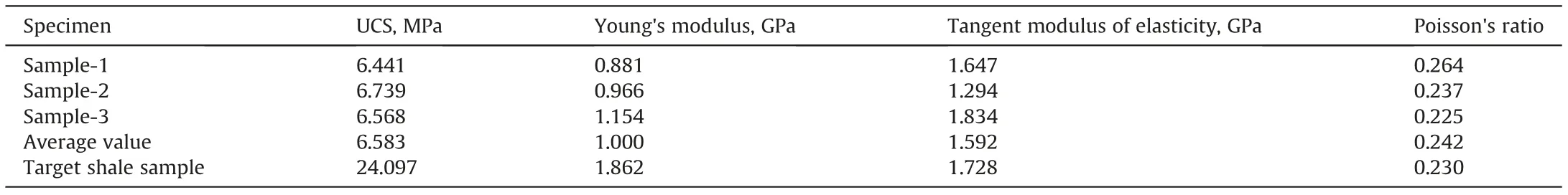
Table 1 Mechanical parameters of artificial specimens.
2.3. Testing and monitoring
2.3.1. Strain monitoring
Due to the existence of strain variation under jet pressurization in both jet perforating and jet fracturing, a new proposed strain testing method is successfully used to monitor and describe the CO2fracturing process (Cai et al., 2019a). There is clearly significant fluctuation of the induced strain in the specimen while the fractures exist. In order to prevent the saturation effect of SC-CO2on the testing, the protective film is pasted to cover the strain gauges and welding position of the signal line (see Fig. 3). Moreover, the artificial shale specimen is set in the high-pressure vessel with sticking strain gauges used to compensate the negative influence of temperature.Notably,the pump should be shut down before strain testing to avoid the disturbance of dynamical pressure influencing.And the strain signal is filtered using the method of fast Fourier transfer(FFT) smooth to pass the interfering signals above 50 Hz.
2.3.2. CO2absorption and specimen mass loss
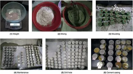
Fig. 2. The schematic procedure for preparing artificial specimens.
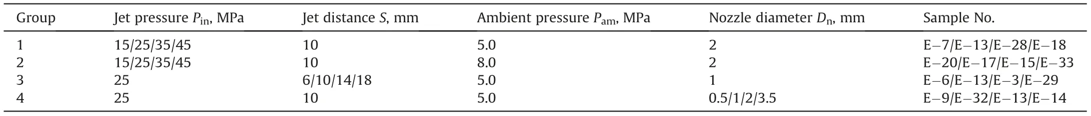
Table 2 Experimental scheme of CO2 jet fracturing.
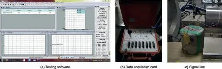
Fig. 3. The strain testing and sample preparation.
It is known that the weight of the shale specimen would change due to the CO2penetration and fracture generation (Cai et al.,2019a). The detailed calculation model has been established in the previous research to investigate the fracture volume and CO2absorption (Cai et al., 2018, 2019a). Thus, to evaluate the CO2absorption of shale specimens, each one is weighed before and after SC-CO2jet fracturing. The variation of specimen weight mostly represents the volume of CO2absorption. Moreover, the mass loss of each specimen is also calculated via testing the specimen weight after over-dried at 105°C for over 120 min to take the absorbed CO2away. Then, the volume variation of each part of the specimen,including the cement, the perforation and the fractures, can be tested using the method of filling salt particle, which is applied in previous studies (Cai et al., 2019a, 2019b; Huang et al., 2018).Finally, the change of specimen weight before and after jet fracturing could be calculated to characterize the fracture volume.
2.4. The mechanism of jet pressurization and strain variation
According to the experimental results and analysis,there are jet impacting part and jet pressurization part(Cai et al.,2020a)(Fig.4).The jet impacting part which results in the SC-CO2jet expansion shows a strongly impacting load in the specimen. For the jet pressurization part which is explored in numerical simulation and experiments before by Wang et al.(2015),Cai et al.(2020a)and He et al. (2015), the induced strain varied with the perforation pressure. The assumptions of a homogeneous, isotropic shale specimens are established in this mechanical model. According to the stress superposition principle, the total tangential stresses on the cylinder surface is expressed as follows (Fig. 5):

where σθtis the total tangential stress on the shale surface,Pa;σθ1is the pressurized stress component induced by the perforation pressure (Pp), Pa, which is the difference value between the jet pressure (Pin) and the ambient pressure (Pam); σθ2is the impacted stress component induced by the jet impact pressure(Psf,Pa).Then,each of the above stress components can be calculated by the method of plate stress with a round hole and half-space stress under normal load, respectively.
2.4.1. The stress component induced by perforation pressurization
According to the elastic mechanic's theory(Xu,2006)and plain strain theory, the radial stress and tangential stress in the hollow cylinder can be expressed as:
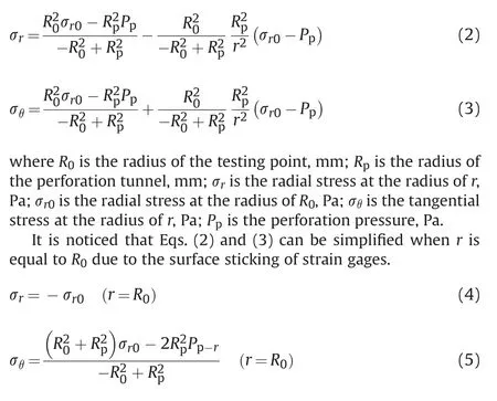
where Pp-ris the perforation pressure when r =R0,Pa,and Pp-r=Pj-Pam;Pjis the jet pressure of the jet core at the axial distance of(z+S) in the submerged environment, Pa; Pamis the ambient pressure,Pa.Therefore,σθ1induced by the perforation pressure can be obtained via Eq. (5).
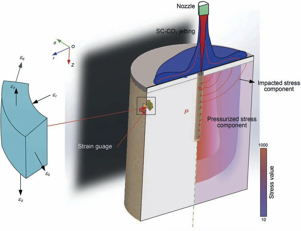
Fig. 4. The mechanical model of the SC-CO2 jet fracturing in a shale specimen.
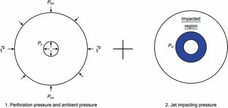
Fig. 5. The schematic of the stress superposition in the specimen section.
It is noticed that σr0=0 in our experiments, because on the sample surface there is no σr0when r = R0. Thus, Eqs. (4) and (5)can be simplified as follows:

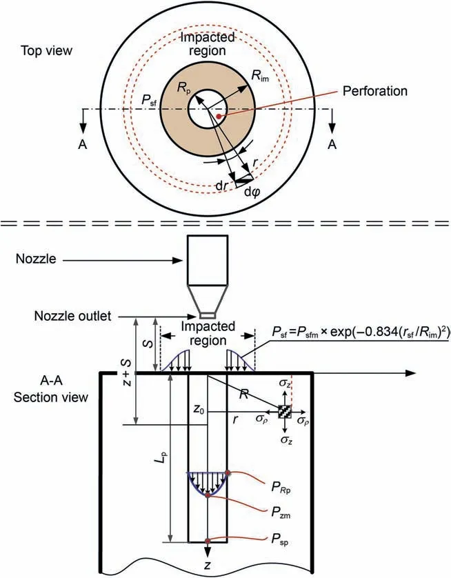
Fig. 6. The schematic of the jet impacting on the artificial specimen surface.
2.4.2. The stress component induced by jet impact pressure
In the SC-CO2jet fracturing, the developing part of SC-CO2jet shows a strong impact on the casing surface and shale.As shown in Fig.6,the red O-ring region represents the impacted area of SC-CO2jetting.Psfon the shale varies with the distance from the center of the perforation,and the maximum pressure value is Psfmwhen r =Rp.It is assumed that the maximum impact radius of the SC-CO2jet is Rimon the top surface of the artificial shale samples. Thus, according to the jet theory (Rajaratnam, 1976; Abramovich et al.,1984), testing results (Hu et al., 2016; Tian et al., 2016) and simulation results(Tian et al.,2016),the distribution of Psfis a similarly exponential function, which can be write as

where Rimis the maximum impacting radius of the SC-CO2jet, m;rsfis the distance from the center of the perforation,varying from Rpto Rim,mm;k0is calculated by the experimental testing;Psfis the jet impact pressure at the radius distance of rsf, Pa; Psfmis the maximum value of impact pressure, Pa.
Then the equivalent uniformly distributed normal load induced by impact load can be expressed by integrating Eq.(8)(Rajaratnam,1976), which is given by:
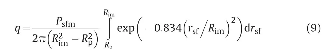
where q is the equivalent uniformly distributed normal load on the top surface under jet impacting.
According to the Boussinesk solution, the axial stress and the tangential stress of micro-unit in the artificial shale sample(Fig.6)can be calculated, respectively, as follows:
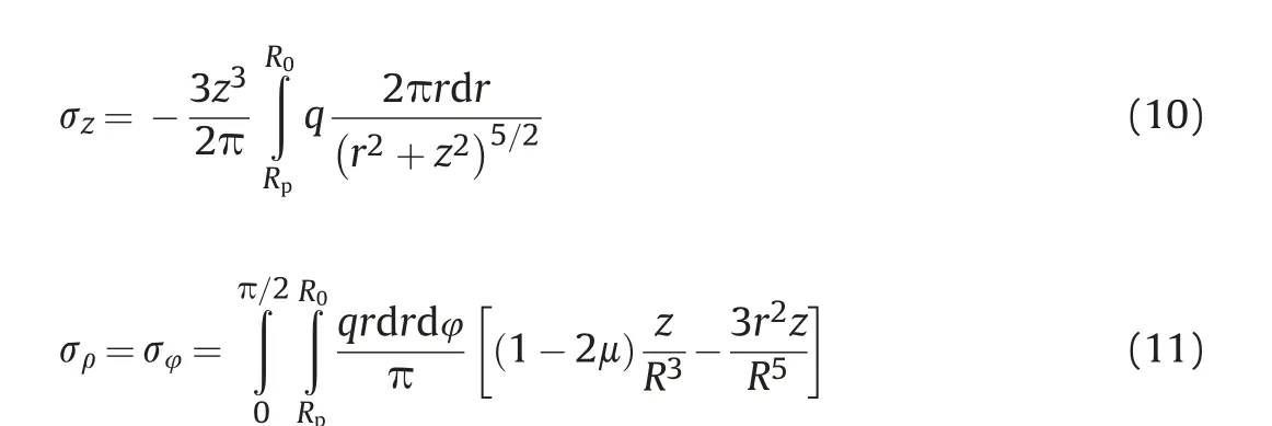
where dr is the width of micro-unit;dφ is the angle of micro-unit;r is the radius distance between the micro-unit and impacting center; z is the axial distance between the micro-unit and the top surface;R is the radius distance between the micro-unit and central axis. Therefore, the stress component (σθ2) induced by the jet impact pressure can be obtained by Eq. (11).
2.4.3. The total stress and strain on the cylindrical surface of the artificial sample
Finally, the total stress on the cylindrical surface of the sample can be obtained by substituting the expressions of Eqs.(7)and(11)into Eq. (1), which is given by
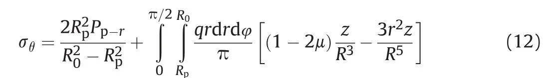
For the axisymmetric cylindrical specimen, the strain can be calculated based on the Hook law and homogeneous and isotropic assumptions. After integrating and considering the relationship of the Pp-ron the perforation surface, Eq. (12) should be changed as follows:
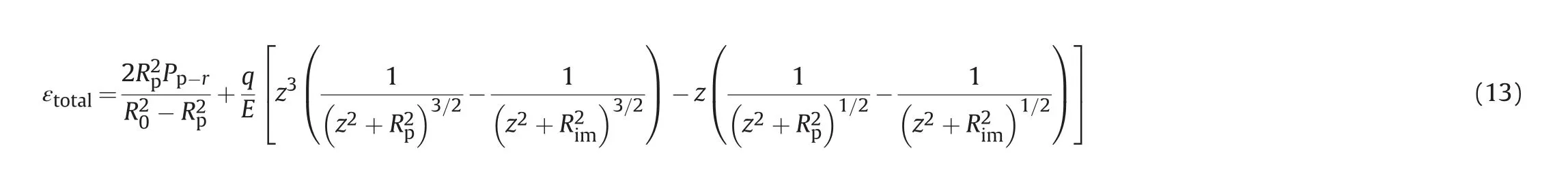
where E is the Young's modulus of samples,GPa.In the right-hand side of the above equation, the first part is the stress component induced by perforation pressurization, and the second part is the stress component induced by jet impacting. Thus,the value tested by the strain gages can represent the varying process of SC-CO2jet fracturing in the experiments.
In the experiments, some parameters are constant values.Because the strain gauges are attached at the position of 15 mm,and the rock sample is a cylindrical structure with constant diameter and height. Thus, it can be obtained that the R0= 50 mm,Rp= 6 mm, z = z0= 15 mm, S = 10 mm. And the maximum impacting diameter of CO2jet can be tested by the high-speed camera (Cai et al., 2020b, 2020c), which is constantly 20 mm.Thereby, Eq. (13) should also be further expressed as follows:
With the experimental results of SC-CO2jet impacting(Hu et al.,2017;Tian et al.,2016),q could be easily obtained.Rimcan be tested by the high-speed camera (Cai et al., 2020b, 2020c), which is constantly 20 mm.The Young's modulus E is 1 GPa.According to the jet theory (Rajaratnam,1976), Pzmis the function of the axial distance of the jet core, which can be described as Eq. (15):
where Pzmis the jet pressure at the axis of the jet core,Pa;Psis the stagnation pressure in the perforation tunnel, Pa, which is dominated by the jet nozzle and ambient pressure;Lpis the perforation depth varied from 5 to 25 mm, which is tested before (Cai et al.,2020c); S is the jet distance between the nozzle and the sample top surface, mm (See Fig. 6).
According to the jet theory (Rajaratnam,1976), the perforation pressure in the perforation (See Fig. 6) can be written as:
According to Eq. (18), it is known that when the perforation pressure varied, the total strain on the sample also changed accordingly. Moreover, the total strain is also related to the jet distance and the rock property. Even the fracture initiates and propagates in this sample, the perforation pressure also changed due to the fracture fluid flowing along the fracture, leading to the variation of the total strain. Thus, the value tested by the strain gages can represent the varying process of SC-CO2jet fracturing in the experiments. This method has been successfully applied for studying SC-CO2jet fracturing before(Cai et al.,2020b, 2020c).
3. Results
3.1. The fracture morphology and induced strain
According to our previous studies (Cai et al., 2018, 2019a),complex fracture networks would be generated in the sample after SC-CO2jet fracturing. For instance, the fracture morphology of the sample is shown in Fig.7.It is found that the sample is divided into three parts by the fractures, which are marked as A, B and C,respectively,in Fig.7b.The fractures initiate at the perforation root,perforation surface, and perforation tip, respectively, resulting in two main fractures. Both on the top surface and the cylindrical surface, two apparent fracture branches are observed, which attributed to the penetration of low-viscosity SC-CO2(Ranjith et al.,2019; Fu and Liu, 2019; X. Li et al., 2019). On the other hand, the fracture network shows the propagation path of a fracture and the rough fracture surface. Similar conclusions have also been pointed out in the previous study, resulting from the SC-CO2unique characteristic (Zhou et al., 2019; Wang et al., 2020; Zhou et al., 2019).
However, despite obtaining the fracture morphology, it is still unknown about the fracturing process and the variation of induced strain in the rock, which is important to verify the numerical simulation.According to the analysis of Section 2.4,the method of strain monitoring is used to identify the fracturing process.To avoid signal interference, the strain data is filtered using the fast Fourier transfer(FFT)method smooth to pass the interfering signals above 50 Hz,as shown in Fig.8a.It is noticed that the curve gradient of the strain curve(tanθ)represents the pressurizing rate of SC-CO2jet in perforation. Moreover, the fluctuation of dynamical strain can be used to identify fracture initiation and propagation.In the previous work, it is believed that a steep drop in strain value is associated with crack initiation (Cai et al., 2019). Therefore, in this case, the comparison between strain value and injection pressure is conducted. It can be seen that when the jet pressure (Pin) starts to quickly rise and sharply drop, accordingly, the strain rapidly increases to the maximum value and then fluctuates in 2.23 s.There are several upper and lower thresholds of strain fluctuations during the pressure variation in short times.In previous research,it is well known that the pressure variation is related to the fracture initiation and propagation during fracturing (Chen et al., 2019;Wang et al., 2019). Therefore, it means the upper and lower thresholds of strain fluctuations also can be used to identify the fracture initiation and propagation. During the increasing term,strain hysteresis is found in the dynamical responses of the artificial sandstone sample which is reported before by Cai et al.(2019a)(See Fig.8b).Thus the fluctuated time is defined as the stable duration,which means the time of fracture initiation and propagation process in the specimen. The residual strain is defined as the strain value when the jet fracturing has been finished. In the reduction term of strain curve,the recovery of strain value can be also seen in some curves which means the stress change in the specimen due to the fracture propagation.
Fig. 7. The fracture morphology of the sample after SC-CO2 jet fracturing (Pin = 35 MPa, Pam = 5.0 MPa).
To investigate the dynamical process of fracture initiation and propagation during SC-CO2jet fracturing, the original strain data(Pin= 35 MPa, Pam= 5.0 MPa) without FFT smoothing is transformed. The frequency variation of strain data can show more dynamic information. Fig. 9 shows the power spectra after FFT and short-time Fourier transform (SFT) smoothing, respectively. According to the power spectrum (see Fig. 9a), it is found that the dominant frequencies are 0.89, 1.89, 13.84, 18.37, and 21.42 Hz,respectively. These additional main frequencies could present the specific amplitudes which are 247.23 × 10⁻⁶, 127.94 × 10-6,52.62 × 10-6, 94.28 × 10⁻⁶, and 122.16 × 10⁻⁶. The frequency reflects the low-frequency pressurization by SC-CO2jet in perforation, the correspondingly induced strain varies from 52 × 10-6to 247×10-6.As shown in Fig.9b,a comparison between the curve of the strain variation and power spectrum variation indicates that the frequency starts changing at first 0.1 s, and keeps rising until at 2.23 s according to the similar increment of strain variation.In this figure,the red color means a high-frequency strain signals and the blue color means a low-frequency strain signals. According to Eq.(11), the change of perforation pressure under SC-CO2jetting results in strain variation with low-frequency. Thus, these variations of frequency intensity could represent the fluctuated intensity of strain in the specimen,which is strongly related to the perforation pressure in the perforation. So the curve of strain variation and power spectrum can be both used to analyze the fracturing process.
3.2. Comparison of hydro-jet fracturing and SC-CO2 jet fracturing
The difference results between water fracturing and gas-based fracturing is explored before using experiments and numerical simulations(Li,S.,et al.,2019;Ranjith,P.G.,et al.,2019).The results indicated that the SC-CO2jet fracturing and liquid nitrogen (LN2)fracturing is regarded as the promising alternate fracturing method for shale gas exploitation due to several advantages (Yang et al.,2019, 2021; Du et al., 2021). However, to clearly get the crack structure,the comparison between water jet fracturing and SC-CO2jet fracturing is carried out using the organic glass to directly view the fracture morphology.As shown in Fig.10a and b,a single main fracture disc is observed when water jet fracturing is performed at 80 and 100 MPa, respectively. The main fracture initiates from the perforation tip and finally propagates with the angle of 45°between the crack plane and the axial direction of the perforation.The abrasives existed in water is contributed to fracture propagation even under low jet pressure. However, many small cracks are generated around the perforation tunnel in the organic specimen using the SC-CO2jet at lower jet pressure of CO2fracturing (See Fig.10c.It is concluded that the fractures propagate along the radial direction of perforation. As expected, the fracture morphology is more complex largely distributed along the perforation tunnel due to the hydraulic and thermal loading (Cai et al., 2018; Yang et al.,2021).
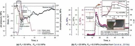
Fig. 8. The variation of jet pressure and strain during SC-CO2 jet fracturing.
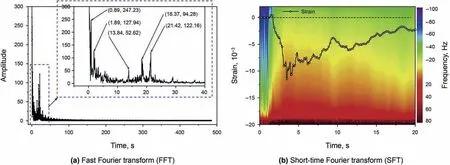
Fig. 9. The spectral response of the strain information during jet fracturing.
4. Discussion
According to Eq. (16), the strain is strongly related to the jet distance and stagnation pressure. The stagnation pressure in the perforation channel varied with the nozzle diameter and ambient pressure(Cai et al.,2020a;Wang et al.,2015).Thereby,based on the experimental results, the influences of various factors on fracture morphology and strain variation were comprehensively studied,such as jet pressure, ambient pressure, jet distance and nozzle diameter.
4.1. Influence of jet pressure
The jet pressure is considered to be one of the main factors affecting jet fracturing. Because as the jet pressure rises, the perforation pressure and the properties of CO2fluid in the perforation would also change consequently, finally influencing jet fracturing. The experiments were conducted and experimental results were compared to analyze the influence of jet pressures at 15,25,35,and 45 MPa,respectively,as shown in Fig.11.According to the crack distribution and morphology,it can be seen that there is no visible crack on the specimen surface under a jet pressure of 15 MPa.With an in increase in jet pressure,the parallel main cracks mainly propagate along the direction perpendicular to the perforation axis under a jet pressure of 25 MPa. However, when the jet pressure increases to 35 MPa, both the parallel main crack and oblique crack are observed in the samples. This phenomenon shows that high-pressure CO2jet fracturing can result in complicated fracture morphology in the specimen. Additionally, a slight damage is also observed in the cement between the casing and the specimen under high-pressure jetting and pressurizing. Cement damage is found on the top of the specimen,suggesting the impact load and pressurizing load by SC-CO2jet. As the jet pressure increase,the oblique cracks created by the jet pressure at 45 MPa are closer to the bottom surface of the sample than those created by the jet pressure at 35 and 25 MPa. Therefore, with the increasing jet pressure, the primary fractures are easily generated close to the bottom surface of the sample, resulting in oblique cracks and substantial cement damage.
Specimen's weight would change after SC-CO2jet fracturing due to the fracture generation and CO2absorption. The weighting method, which has been successfully applied in the analysis of specimen mass loss and volume change (Cai et al., 2019a; Huang et al., 2017, 2020), is used to calculate the CO2absorption and mass loss of the specimen. The results indicate that both the mass loss of the specimen and CO2absorption significantly increase with an increase in jet pressure (Fig. 12). These results are consistent with the above fracture morphology in Fig.11, and conform to the leak-off principle under a higher injection pressure (Meier et al.,1997). Due to the high-pressure CO2penetrating and carrying,numerous minerals and particles inside the specimen are readily carried off from the fracture to the outside of specimen,resulting in mass loss of specimen after fracturing experiment. Thus, under a high jet pressure, the increasing mass loss is mainly attributed to fracture generation and cement damage (Fig. 12). Moreover, the results also indicate that the high jet pressure is one of the major reasons for the rising CO2absorption in specimens.
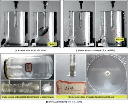
Fig.10. A comparison between water jet fracturing and SC-CO2 jet fracturing.
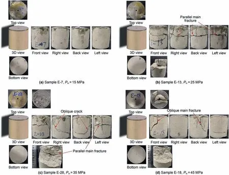
Fig.11. Fracture morphology under different jet pressures (Pam = 5.0 MPa, Dn = 2 mm, S = 10 mm).
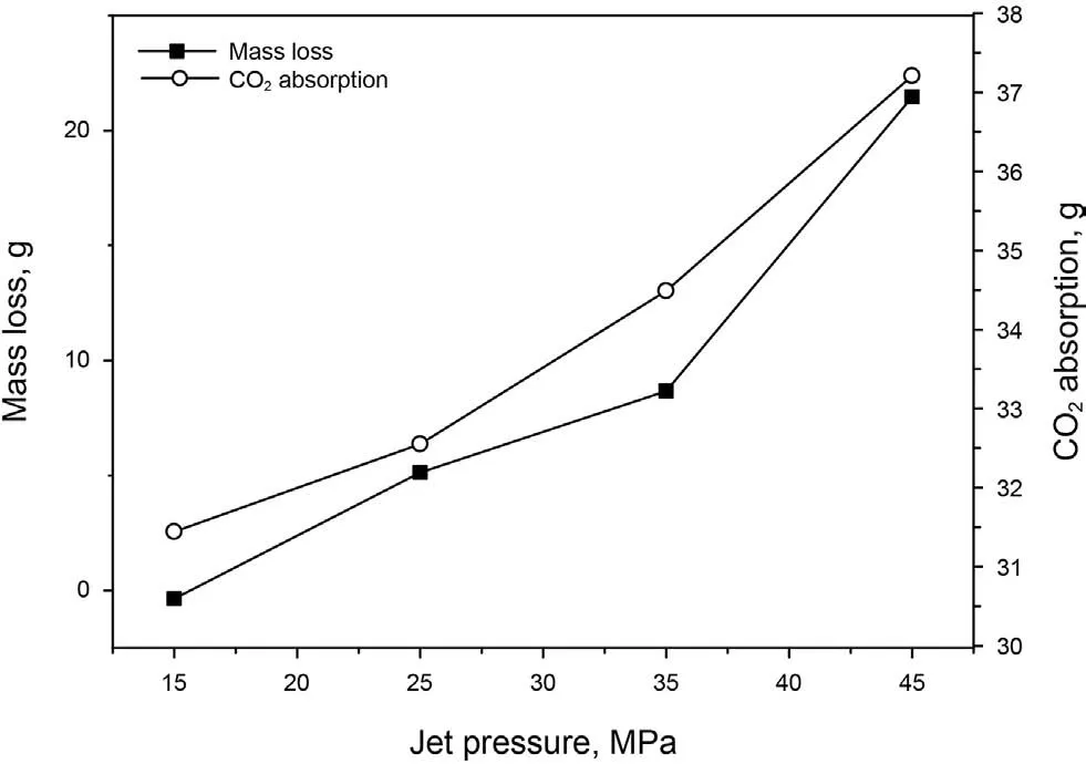
Fig.12. Variations of mass loss and CO2 absorption with jet pressure (Pam = 5.0 MPa,Dn = 2 mm, S = 10 mm).
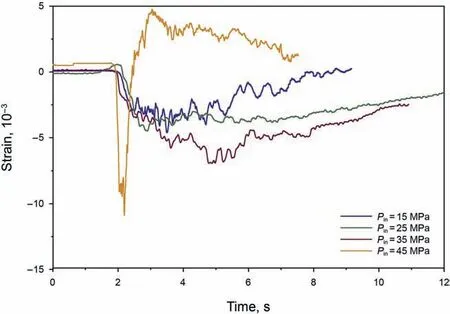
Fig.13. The strain variation under different jet pressures (Pam= 5.0 MPa,Dn = 2 mm,S = 10 mm).
Fig.13 shows the variation of strain with jet pressure.It is found that the minimum strain on the sample gradually grows with the increasing jet pressure.Residual strain also gradually goes up when the jet pressure increases from 25 to 35 MPa. Thus, increasing jet pressure is exceedingly crucial for enhancing fracturing. Furthermore,under a jet pressure of 45 MPa,the strain rapidly increases to its minimum value of -10.9 × 10⁻³in only 0.3 s and then quickly rises to 5.0 × 10⁻³in a short time. Combining with the fracture morphology under a jet pressure of 45 MPa(Fig.11d),it can be seen that the main crack propagates from the perforation surface to the specimen surface,thus resulting in a sharp fluctuation of the strain curve.Therefore,the strain variation under a jet pressure of 45 MPa is different from that under other jet pressures(Fig.13).
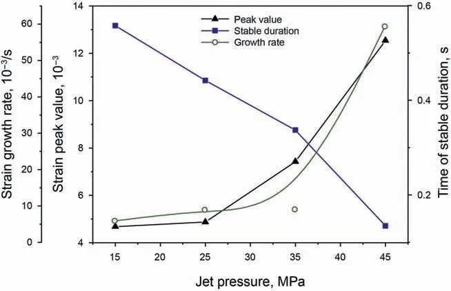
Fig. 14. Variations of the growth rate, stable duration and minimum value of strain with jet pressure (Pam = 5.0 MPa, Dn = 2 mm, S = 10 mm).
From the strain variation curves(Fig.13),the growth rate,stable duration and minimum value of strain are collected (Fig. 14). It clearly illustrates that both the growth rate and minimum strain rise exponentially, especially under the jet pressure of above 25 MPa. However, the time of stable duration declines with an increase in jet pressure. The main reason is that the jetting time becomes shorter when the jet pressure increases due to the limited volume of high-pressure CO2stored in the vessel.
4.2. Influence of ambient pressure
The influence of ambient pressure on fracture generation in organic glass has been investigated (Cai et al., 2018). Some conclusions have been drawn that the increasing ambient pressure could prevent the generation of more fractures due to the reduction in the pressure difference between the jet pressure and ambient pressure. This study aims to investigate the strain response in the rock under different ambient pressures.Thus,four specimens were used to undertake the same jet fracturing studies at an ambient pressure of 8.0 MPa, and the experimental results (Fig. 15) were compared with those obtained from the tests performed under an ambient pressure of 5.0 MPa (Fig. 11). When the jet pressure is 15 MPa, there is no fracture generated on the surface of the specimen(Figs.15 and 11).However,cement damage could be found on the top surface of the specimen.The damage to the perforation root and cement under the higher ambient pressure(Fig.15a)are more significant than those under a jet pressure of 15 MPa (Fig. 11a).When the jet pressure increases from 25 to 45 MPa,a large number of fracture branches form, and the main fracture pattern changes from bent dual-wing fractures to multiple fractures. We can infer that the ambient pressure affects the fracture propagation path.Unlike the case of a low ambient pressure,the main fractures under a high ambient pressure mostly extend from the top surface to the bottom surface.

Fig.15. Fracture morphology under different jet pressures (Pam = 8.0 MPa, Dn = 2 mm, S = 10 mm).
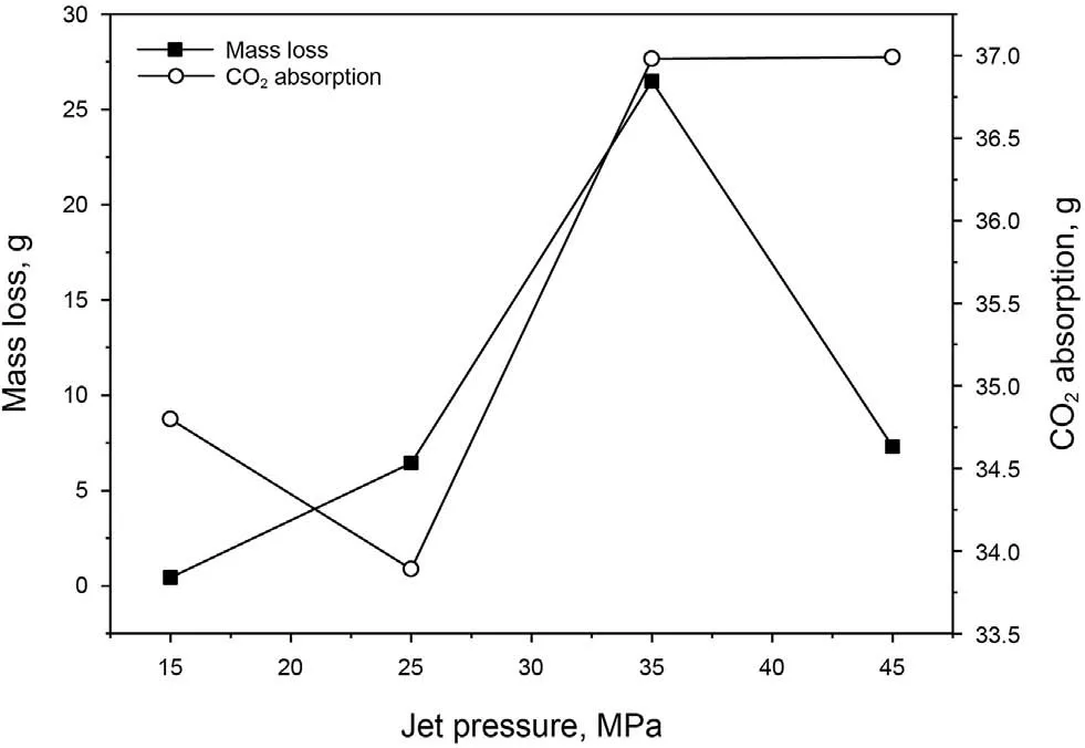
Fig.16. Variations of mass loss and CO2 absorption with jet pressure (Pam = 8.0 MPa,Dn = 2 mm, S = 10 mm).
Furthermore,the mass loss and CO2absorption of the specimen under a high ambient pressure are also different from the cases under a low ambient pressure. Similarly, with increase in jet pressure CO2absorption also generally keeps rising trend and slightly increases when the jet pressure increases to above 35 MPa(Fig.16).However,the mass loss of the specimens firstly shows an increasing trend (15-35 MPa) and then decreases (45 MPa). The cement damage might be ascribed to the impact of SC-CO2jet under a high ambient pressure.Wang et al.(2015)also reports that the ambient pressure affects the jet flow,and results in different jet pressurization and jet impact. Thus, the higher CO2absorption could be obtained under the higher ambient pressure.
According to the variation of strain(Fig.17),the most important clinically relevant finding is that the minimum strain gradually decreases with the increase in jet pressure.It also can be seen that the growth rate of strain in the pressurization process increases with the increase in jet pressure.Otherwise,the results of extreme fluctuation of strain in the stable duration under the higher jet pressure indicate that the fluctuated strain is closely related to the jet pressure and suggest the events of crack generation. Unexpectedly, all the strain curves show the phenomenon of strain recovery. It should be highlighted that the maximum strain value under the higher ambient pressure is 1.5 times of that under an ambient pressure of 5 MPa(Fig.18).In the four stable durations of the strain curves,when the jet pressure grows,the stable duration decreases exponentially, displaying the same decreasing trend as that under a low ambient pressure. Notably, for the same jet pressure, the stable duration under a high ambient pressure is 9 times of that under a low ambient pressure under the same jet pressure. The above results demonstrate that increasing jet pressure could enhance jet fracturing, as confirmed in the previous study (Cai et al., 2018).
4.3. Influence of jet distance
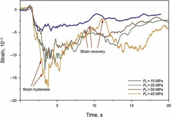
Fig. 17. Variations of strain curves under different jet pressures (Pam = 8.0 MPa,Dn = 2 mm, S = 10 mm).
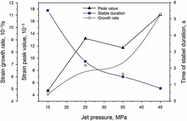
Fig.18. Variations of growth rate, stable duration, and minimum value of strain with jet pressure (Pam = 8.0 MPa, Dn = 2 mm, S = 10 mm).
According to the images of high-speed photography (HSP) (Cai et al., 2020a), the penetration depth of the SC-CO2jet is related to the jet distance, which apparently affects the jet fracturing. The fracture morphology under different jet distances is compared, as shown in Fig.19.It is clear that three main fractures are observed in the specimen under a jet distance of 6 mm, but only two main fractures are observed under the other jet distances. These results confirm the correlation between optimal jet distance and generated fractures.With the increase in jet distance,the pattern of main fractures,including both oblique fractures and transverse fractures,are changed from complex morphology to single longitude fractures. Cai et al. (2018) previously observed the same results in the organic glass specimen. The distribution of fracture branches indicate that the fracture branches mostly occur on the cylindrical surface of the specimen when the jet distance increases from 6 to 14 mm, except the jet distance exceeding 18 mm.
Moreover,Fig.20 summarizes the mass loss and CO2absorption under different jet distances from 6 to 18 mm.With the increase in jet distance, both the mass loss and CO2absorption firstly shapely rise to the maximum value and then gradually decrease. Mainly,under a jet distance of 10 mm, both the mass loss and CO2absorption reach peak values.The observed increase in mass loss and CO2absorption could be attributed to the optimal jet distance,which allows the optimal pressurization results in perforation(Tian et al., 2016).
Furthermore, Fig. 21 shows strain curves and Fig. 22 shows the characterized parameters,such as minimum value,growth rate and stable duration. In Fig. 21, the minimum value and residual strain under a distance of 6 mm are both less than those under other cases. That means too shorter jet distance is not beneficial to jet fracturing.Combined with the results of Figs.21 and 22,it is found that the minimum value of strain under a jet distance of 10,14,and 20 mm are larger than that under a jet distance of 6 mm.According to the HSP results(Cai et al.,2020c),these results are ascribed to the jet flow. Surprisingly, when the jet distance is between 10 and 14 mm the growth rate of strain is highest, indicating that the optimal jet distance can positively affect jet fracturing.The curve of the stable duration varies with jet distance increasing, indicating that the optimal jet distance is between 10 and 14 mm(5-7 times of the nozzle diameter). These results are also similar to the previous data(Cai et al.,2018;Hu et al.,2017).The optimal jet distance would result in the best pressurization effect in perforation.
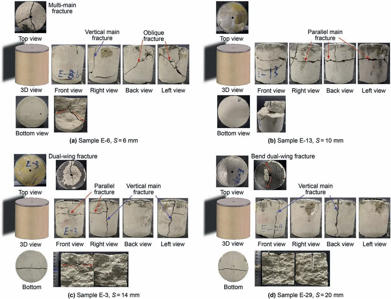
Fig.19. Fracture morphology under different jet distances (Pin = 25.0 MPa, Dn = 2 mm, Pam = 5.0 MPa).
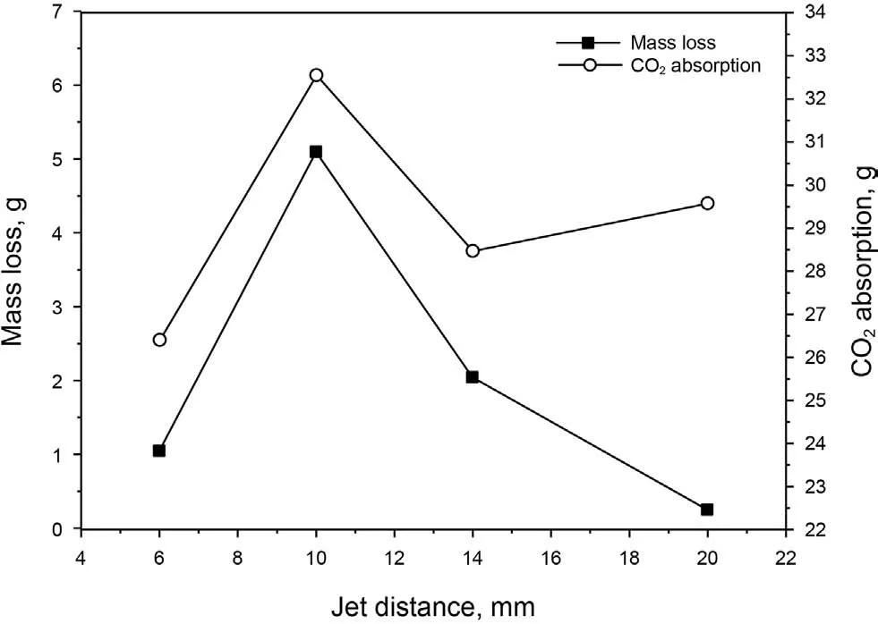
Fig. 20. Variations of mass loss and CO2 absorption with jet distance (Pin = 25.0 MPa,Dn = 2 mm, Pam = 5.0 MPa).
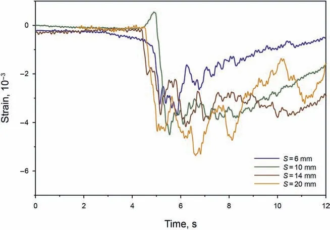
Fig. 21. Strain curves under different jet distances (Pin = 25.0 MPa, Dn = 2 mm,Pam = 5.0 MPa).
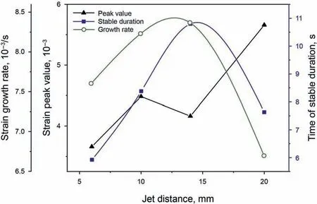
Fig.22. Variation of growth rate,stable duration,and minimum value of strain with jet distance (Pin = 25.0 MPa, Dn = 2 mm, Pam = 5.0 MPa).
4.4. Influence of nozzle diameter
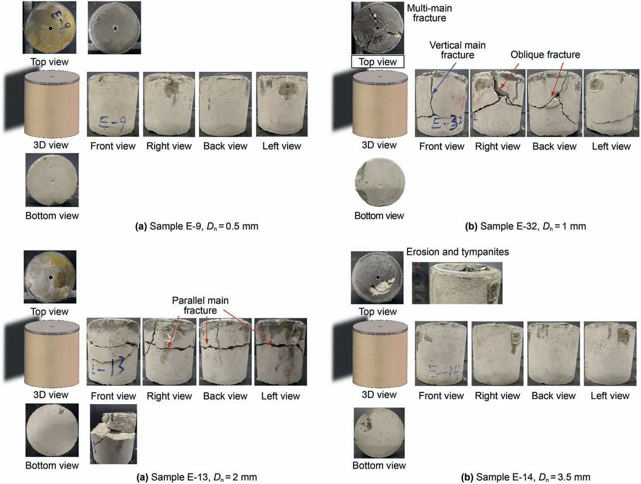
Fig. 23. Fracture morphology under different nozzle diameters (Pin = 25.0 MPa, S = 10 mm, Pam = 5.0 MPa).

Fig. 24. Variations of mass loss and CO2 absorption with nozzle diameter(Pin = 25.0 MPa, S = 10 mm, Pam = 5.0 MPa).
When the perforation diameter is constant, the varied nozzle diameter affects the length and width of the jet core and the flow rate of SC-CO2jetting in perforation(Cai et al.,2020c).As shown in Fig. 23, when the nozzle diameter varies from 0.5 to 3.5 mm,complex fractures could be obtained on the surface of the specimen when the nozzle diameters are 1 and 2 mm,respectively.According to HSP images(Cai et al.,2020c), too small nozzle diameter would reduce the length and width of the jet core,consequently resulting in poor pressurization effect in perforation. On the contrary, too large nozzle diameter mostly leads to a large area of impact,so less CO2enters the perforation. That is the reason the optimal ratio of nozzle diameter to perforation diameter is from 1:3 to 1:6, as reported by Tian et al.(2016),Wang et al.(2015)and Hu et al.(2017).Therefore, under a nozzle diameter of 1 mm, the length of the longitudinal fracture formed on the specimen surface is longer than that under a nozzle diameter of 2 mm. The observed oblique fracture also supports the above results.
In addition to the fracture morphology, the mass loss and CO2absorption also supports the above results that the optimal nozzle diameter is 1 or 2 mm while there are a higher mass loss and CO2absorption than that under the nozzle diameter of 0.5 and 3.5 mm(Fig. 24). Based on the flow field (Cai et al., 2020c), the results are related to the longest penetrating depth of SC-CO2jet under the optimal nozzle diameter of 1 or 2 mm.
When the nozzle diameter is 0.5 mm, the strain increases smoothly without large fluctuation (Fig. 25). The smallest value of the minimum strain is also consistent with the results of fracture morphology. When the nozzle diameter increases from 1 to 3.5 mm, the minimum strain also increases from 3.8 × 10⁻³to 9.1×10⁻³.Thus,the variations of strain is strongly correlated to the fracture generation in the specimen. The largest value of the minimum strain is obtained under a nozzle diameter of 3.5 mm because the highest impacting region of jet is on the top surface of the specimen(Fig.26).As shown in Fig.26,with the increase in nozzle diameter,the growth rate of strain quickly goes up to the peak value and gradually reduces because the jet pressure reduces with the increase in nozzle diameter. In addition, the stable duration displays an exponential reduction because the smaller does the nozzle diameter allowed the longer of jetting time under the same high pressure of the vessel,which is used to store the high-pressure SCCO2before jet fracturing. Therefore, the variations of strain and fracture morphology indicate that the optimal nozzle diameter is 1 mm.
4.5. Nonlinear variation of strain with jet pressure
Jet pressurization is crucial for SC-CO2jet fracturing and has been extensively investigated.Some works have been conducted to explore jet pressurization mechanism by using numerical simulation (Wang et al., 2015; He et al., 2015). However, the relationship between jet pressurization and strain variation in the rock is still not clear.In this study,the relationship is studied though 14 group experiments (Fig. 27).
The extreme values of strain under different jet pressure are shown in Fig. 27. Interestingly, even though the strain value increases with the increase in jet pressure, there is an apparent nonlinear variation of strain.As indicated in Eq.(16),the reason for the nonlinear variation is attributed to the different impacting loads and ambient pressures.With the increase in jet pressure,the impacting load and ambient pressure also increase significantly,thus leading to the nonlinear rising of strain. According to the elastic mechanism, under the same jet pressure and ambient pressure,the ratio of strain to shale strain can be expressed as:
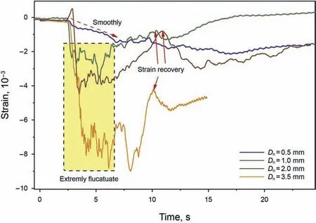
Fig. 25. Variations of strain under different nozzle diameters (Pin = 25.0 MPa,S = 10 mm, Pam = 5.0 MPa).
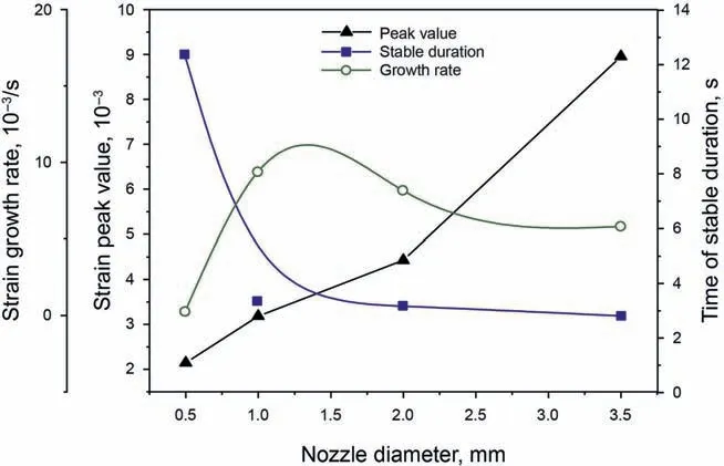
Fig. 26. Variations of growth rate, stable duration, and minimum value of strain with nozzle diameter (Pin = 25.0 MPa, S = 10 mm, Pam = 5.0 MPa).
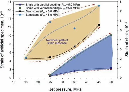
Fig. 27. Nonlinear variation of strain with jet pressure.
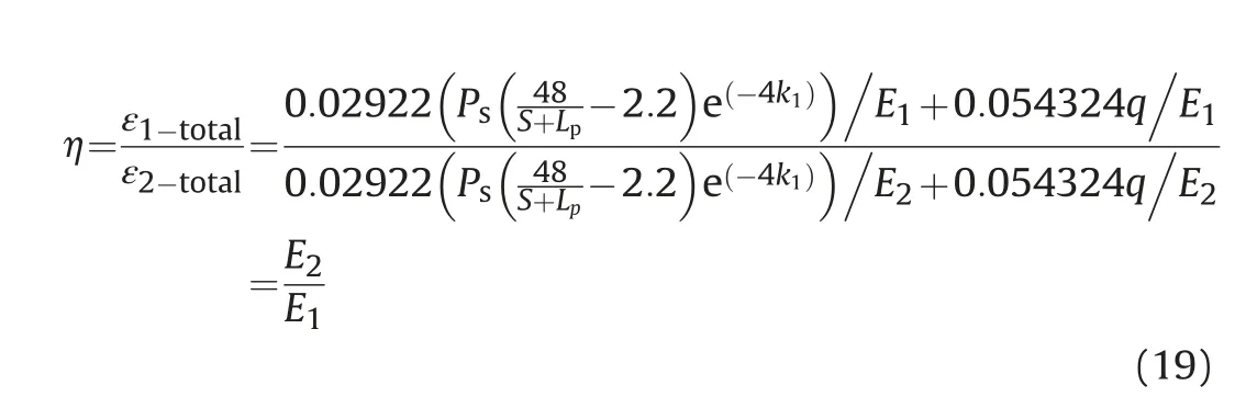
where ε1-totaland ε2-totalare the extreme strain values of sandstone and shale, respectively; E1and E2are the Young's modulus of artificial specimen and shale rock, respectively.
It is found that this nonlinear variation of strain is related to the ambient pressure and depends on the rock type(Fig.27).Compared with the artificial specimen and shale rock, the extreme strain of sandstone is higher than that of shale under the same jet pressure and ambient pressure. The average Young's modulus and average uniaxial compressive strength of shale are 17 GPa and 24 MPa,respectively (Cai et al., 2019a), whereas the average Young's modulus and average uniaxial compressive strength of the artificial specimen is 1.0 GPa and 6.5 MPa, respectively (See Table 2). It is found the ratio of strain (η) between artificial specimen and shale rock varied from 2.7 to 12, which is also closed to the ratio of Young's modulus. Therefore, the study suggests that both the Young's modulus of the rock and jet pressure are the two main factor which can produce a different nonlinear strain variation.
5. Conclusions
Based on the results and discussion,we can draw the following conclusions:
(1) Fast Fourier transfer (FFT) results indicate that the main frequencies of stain data are respectively 0.89, 1.89, 13.84,18.37, and 21.42 Hz, whereas the corresponding amplitudes are 247.23×10-6,127.94×10-6,52.62×10-6,94.28×10-6,and 122.16×10⁻⁶.The strain response and its SFT can clearly show the dynamical process of SC-CO2jet fracturing.
(2) Under a high ambient pressure of 8.0 MPa, the CO2absorption generally rises, whereas the mass loss of specimens firstly increases and then decreases with the increase in jet pressure. The maximum strain value under the higher ambient pressure is 1.5 times of that under an ambient pressure of 5.0 MPa. For the same jet pressure, the stable duration under a high ambient pressure is 9 times longer than that under a low ambient pressure.
(3) With the increase in jet pressure,the fracture morphology is changes from parallel cracks to oblique cracks. Correspondingly,both the growth rate and the minimum value of strain exponentially increase.With the increase in jet distance,the pattern of main fractures, including both oblique fractures and transverse fractures, are changed from complex morphology to single longitude fractures,and the peak value of strain increases and then reduces.The optimal jet distance is 10-14 mm,and 5-7 times of the nozzle diameter.Complex fractures are formed on the surface of the specimen under the nozzle diameter of 1 and 2 mm.
(4) Even though the strain value increases with an increase in jet pressure, the nonlinear variation of strain is significant during jet pressurization.Both the Young's modulus of the rock and jet pressure are the two main factor which can produce a different nonlinear strain variation.
Acknowledgments
The authors express their appreciation to the National Natural Science Foundation of China(Grant No.52004236),Sichuan Science and Technology Program (Grant No. 2021JDRC0114), the Starting Project of SWPU (Grant No. 2019QHZ009), the China Postdoctoral Science Foundation (Grant No. 2020M673285), the Open Project Program of Key Laboratory of Groundwater Resources and Environment (Jilin University), Ministry of Education (Grant No.202005009KF) and the National Key Basic Research Program of China (Grant No. 2014CB239203) for the financial support of this work. The authors also appreciate the help of experimental conducting through Chen Hao and Wang Zu'an (Wuhan University).
杂志排行

Petroleum Science的其它文章
- A fast space-time-domain Gaussian beam migration approach using the dominant frequency approximation
- Predicting gas-bearing distribution using DNN based on multicomponent seismic data: Quality evaluation using structural and fracture factors
- Reflection-based traveltime and waveform inversion with secondorder optimization
- Determination of dynamic capillary effect on two-phase flow in porous media: A perspective from various methods
- Settling behavior of spherical particles in eccentric annulus filled with viscous inelastic fluid
- Laboratory investigation on hydraulic fracture propagation in sandstone-mudstone-shale layers