Damage of reservoir rock induced by CO2 injection
2022-09-23JingLiZhoYngChenYongCunFengLiShQuJiGengLiuWenYnLiMengYingDi
Jing Li ,Zho-Yng Chen ,Yong-Cun Feng ,Li-Sh Qu ,Ji-Geng Liu ,Wen-Yn Li ,Meng-Ying Di
a College of Pipeline and Civil Engineering, China University of Petroleum, Qingdao, 266580, Shandong, China
b College of Petroleum Engineering, China University of Petroleum, Beijing,102249, China
c School of Geosciences, China University of Petroleum, Qingdao, 266580, Shandong, China
d Research Institute of Exploration and Development, PetroChina Tarim Oilfield Company, Korla, 841000, Xinjiang, China
Keywords:CO2 injection Seepage-stress-damage coupling Rock damage Numerical simulation
ABSTRACT The study of reservoir rock damage induced by gas injection is of great significance to the design of reservoir stimulation and the improvement of oil and gas recovery.Based on an example horizontal well in the Hudson Oilfield of the Tarim Basin and considering the multi-physics coupling effects among highpressure fluid, rock deformation, and damage propagation during CO2 injection, a three-dimensional finite element model for CO2 injection in deep reservoir considering seepage-stress-damage coupling was developed. The evolution of reservoir rock damage under different CO2 injection conditions was systematically investigated.The results show that tensile damage and shear damage are concentrated in the vertical direction and the horizontal maximum compressive principal stress direction, respectively,and the tensile damage is the main damage mode. At higher CO2 injection rate and pressure, the damaged areas near the wellbore are mainly distributed in the direction of the maximum compressive principal stress, and the development of the damaged area near the wellbore will be inhibited by the formation and evolution of far-field damage. CO2 injection aggravates the extension of tensile damage,but inhibits the initiation of shear damage, and eventually leads to the gradual transition from shear damage to tensile damage.Under the same injection conditions,CO2 injection has superior performance in creating rock damage compared with the injection of nitrogen and water. The results in this study provide guidance for enhanced oil recovery in deep oil and gas reservoirs with CO2 injection.
1. Introduction
With the increasing demand for energy over the world, it is an inevitable trend that the focus of oil and gas exploration and development shifts from shallow reservoirs to deep reservoirs (Li et al., 2021b, 2021c; Zeng et al., 2020). The reservoir of the Hudson oilfield in Tarim Basin is buried at depth of more than 5000 m,and the development of this type of reservoir is restricted by high confining pressure and complex burial conditions. Therefore,effective means are urgently needed to stimulate the reservoir to obtain desired production(Feng et al.,2017;Guo et al.,2019;Zhang et al.,2021a,2021b).To improve oil and gas recovery,water or gas are usually injected into the reservoir to break the rock mass and to form a complex fracture network with high permeability to facilitate fluid flow from the reservoir to the wellbore(Fallahzadeh et al.,2017;Feng et al.,2016;Kostina et al.,2019;Zhou and Burbey,2014).The fluid or gas flow within the fractures during injection promotes the expansion and extension of the fractures, causing the increase in porosity and permeability of the reservoir rock. In turn, the pressure distribution and seepage of the pore fluid will be affected by the damage of the rock mass.Thus,the fluid/gas-solid coupling effect exists in the rock damage process of fluid/gas injection (Jia et al., 2018; Li et al., 2021a; Xue et al., 2018; Yang and Huang,2020; Zhao et al., 2017; Zhou et al., 2016).
Research on rock damage under multi-physics coupling has been carried out by many scholars. Wang et al. (2016) derived the damage constitutive model of heterogeneous rock based on the Druker-Prager strength criterion and developed a program for calculating permeability change with rock damage. Zhu et al.(2009) proposed a thermal-hydraulic-mechanical coupling model in the process of rock damage and analyzed the effect of fluid pressure on rock damage. Pogacnik et al. (2016) modeled the damage evolution and permeability enhancement during hydraulic fracturing using a mixed fracture mode model. Chen et al. (2018)studied the coupling between permeability evolution and rock damage of heterogeneous reservoirs and found that stress sensitivity factor and damage coefficient are the key variables that control permeability evolution. Yi et al. (2019) proposed a fully coupled fluid flow and rock damage model to study the effects of injection velocity, fluid viscosity, and confining pressure on rock damage. Hou et al. (2017) proposed an improved criterion for determining fracture initiation pressure and investigated its sensitivity to different fracturing fluids. Liu et al. (2016) demonstrated that the injection of supercritical CO2can cause rock damage and permeability increase.Zhang et al.(2017)investigated the effects of different fracturing fluids, rock permeability, and injection rate on fracture initiation pressure and seepage sweep area.The results show that with the increase in permeability anisotropy and fluid compressibility,the fracture initiation pressure decreases and the seepage sweep area increases. Lu et al. (2013) proposed a continuum mechanics of textured polycrystals method based on a two-scale conceptual model and studied the rock damage evolution process from random microcracks to macroscopic local fractures in permeable rocks under the action fluid injection.
However, most of the aforementioned studies did not consider the real reservoir environment and in-situ stress condition, and most of the numerical models are two-dimensional,which cannot sufficiently characterize the complex damage evolution process of deep reservoir rocks. Therefore, taking a horizontal CO2injection well HD4-59H in the Hudson oilfield of Tarim Basin as an example,a three-dimensional finite element model with seepage-stressdamage coupling was developed in this paper to simulate the damage evolution in the reservoirs during CO2injection. Damage evolution with different CO2injection conditions was systematically studied, so as to provide theoretical support for optimizing reservoir stimulation design.
2. Governing equations
Based on the theories of continuum mechanics, fluid flow in porous media, and damage mechanics, this section establishes a coupled seepage-stress-damage model for gas injection. The interaction between rock damage and fluid seepage during the process of gas injection is also discussed. The accuracy of the proposed model was verified by comparing it against two classical theoretical solutions and existing experimental results.
2.1. Rock deformation and damage
Reservoir rock is considered a linear elastic material in this study. Thus, the stress-strain relationship obeys the generalized Hooke's law. Considering the influence of pore pressure, the governing equation of rock deformation is expressed as (Wei et al.,2015):

where σijand εijare the stress tensor and strain tensor(The tensile stress/strain is positive and the compressive stress/strain is negative), respectively; G=E/2(1+v) is the shear modulus of rock; E and v are the elastic modulus and Poisson's ratio,respectively;εv=ε11+ε22+ε33is the volumetric strain; δijis Kronecker delta; α is the Biot coefficient;p is the pore pressure.
According to the theory of elasticity, the relationship between rock strain and displacement is expressed as:

where fiis the component of the body force in the i direction;p'iis the partial derivative of the pore pressure in the i direction.
The method of combining the maximum tensile stress failure criterion and the Mohr-Coulomb shear failure criterion to characterize the damage state of rock was used in this paper. When the stress state at a certain point of rock satisfies the maximum tensile stress criterion or the Mohr-Coulomb shear failure criterion, the rock is considered to have tensile damage or shear damage. The expressions of the two criteria for judging rock damage are (Zhu et al., 2003):
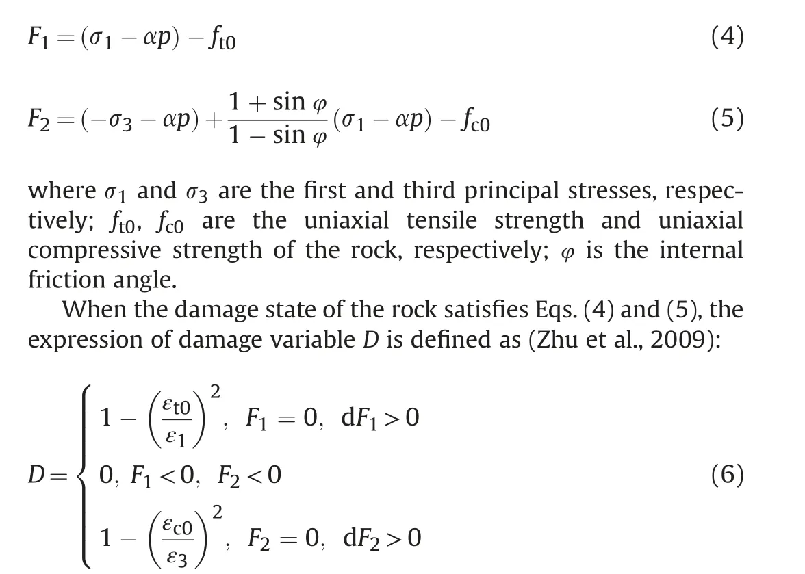
where ε1and ε3are the first and third principal strains, respectively; εt0and εc0are the maximum tensile principal strain and maximum compressive principal strain corresponding to tensile failure and shear failure of rock, respectively.
The elastic modulus of rock gradually degenerates with the development of damage, expressed as:

2.2. Fluid flow
The fluid is considered as a single-phase compressible fluid.It is assumed that the fluid flow obeys Darcy's law and satisfies mass conservation:

where K0is the initial permeability;αkis a coefficient indicating the effect of damage on the permeability.
2.3. Characterization of rock heterogeneity
The Weibull distribution function is used to describe the heterogeneity of rocks (Wang et al., 2016). In the simulations, the model is divided into multiple units and the basic physical parameters of rock are assigned to follow Weibull distribution to represent the heterogeneity of the rock.The Weibull distribution of a variable is expressed as:
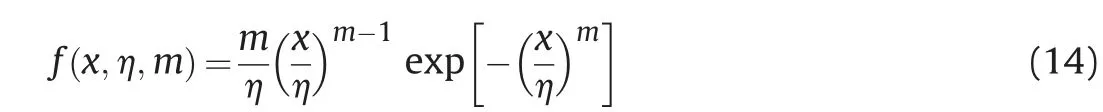
where x is basic variables;η is parameter average; m is the coefficient of heterogeneity.
2.4. Model verification
For isotropic porous media,two classic criteria are usually used to calculate the fracture pressure in two extreme cases. Hubbert and Willis (1957) carried out theoretical research on hydraulic fracturing of horizontal wells under far-field stress,and proposed a theoretical solution of the fracture pressure of impermeable rocks.Haimson and Fairhurst (1967) considered the porous elastic stress caused by fluid infiltration into the rock,and proposed a theoretical solution of the fracture pressure of permeable rocks. In order to verify the rationality of the numerical damage model proposed in this paper, the numerical simulation results are compared with Hubbert Willis (H-W) solution, Haimson-Fairhurst (H-F)solution, and experimental data from Song et al. (2001), respectively. The mechanical parameters used in the simulation are shown in Table 1, the same as those in Song et al. (2001).
Fig.1 shows that the fracture pressure obtained with numerical simulation is higher than the H-F theoretical solution but lower than the H-W theoretical solution because the rock permeability used in the simulation is between the impermeable rock of the H-W solution and the permeable rock of the H-F solution.Meanwhile, the fracture pressures at different confining pressure values obtained with the simulation are in good agreement with the experimental data,which well expresses the linear relationship between fracture pressure and confining pressure. Thus, the comparison verifies the reliability and accuracy of the numerical model.
3. Numerical model development
The study area of the horizontal well HD4-59H is located on the Had 4 structure of the Hudson structural belt in the northern Manjiaer Sag, Tarim Basin, China. The buried depth of the horizontal section is between 5067.33 and 5067.62 m. The geological environment of the reservoir in this area is complex with low porosity and medium to low permeability.The effective porosity of the reservoir ranges from 7.5% to 16.6%, with an average of 13.6%;the permeability is between 0.31×10⁻³and 84×10-3μm2,with an average of 38.1 × 10⁻³μm2.
Based on the layout of the horizontal well, a square area of the wellhead of the horizontal well is selected as the scope of this study. A three-dimensional gas injection model is established as shown in Fig.2.The upper boundary of the model bears vertical insitu stress σV; the horizontal boundaries bear the maximum horizontal in-situ stress σHand the minimum horizontal in-situ stress σh,respectively.The remaining outer boundaries are constrained by rollers. The horizontal gas injection well is located in the center of the model with a radius of 0.1 m. The length of the gas injection section is 8 m as highlighted in red in Fig. 2. No flow boundary is defined at both ends as highlighted in blue. The average porosity and permeability of rock are taken as initial parameters in the simulation, and other model parameters are listed in Table 2.
4. Results
The horizontal well is in a state of high confining stress due to the loading of the upper rock mass and the stress induced by the geological structure. The damage is more likely to occur in the region near the wellbore due to local stress concentration.Therefore,in this section, the evolution of rock damage near the wellbore under the action of in-situ stress and different CO2injection conditions is investigated.
4.1. Initial damage state of reservoir rock
Before CO2injection, the stress concentration near the horizontal well induces initial damage to the rock mass.Fig.3 shows the distribution of initial rock damage around the well.The color in the figure represents different damage degrees: the red colorrepresents high damage degree and the blue color represents relatively low damage degree. Under the action of high confining pressure, due to the heterogeneity of the rock, discretely distributed damage regions appear in the reservoir, and the damage degree of the inner wall is obviously higher.Comparing Fig.3a and b,it can be seen that the tensile damage is mainly concentrated in the X-Y plane due to the influence of vertical in-situ stress, while the shear damage is mainly concentrated in the X-Z plane in the horizontal in-situ stress direction.At the initial state,the tensile damage accounts for 54% of the total damage, and the damage degree and range of rock caused by tensile failure are generally higher than the shear damage.
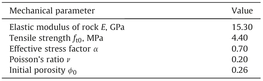
Table 1 Computational parameters.

Fig.1. Relationship between the fracture pressure and the confining pressure.
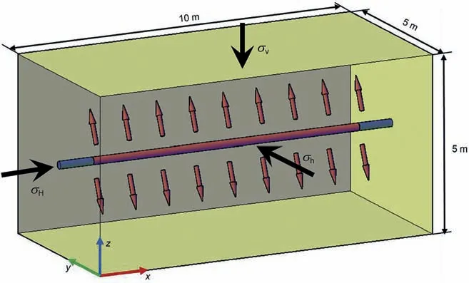
Fig. 2. The numerical model of CO2 injection.
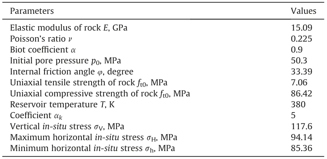
Table 2 Basic parameters of the numerical simulations.
4.2. The influence of CO2 injection rate
The above boundary stress conditions remain unchanged during the simulation. When the high-pressure carbon dioxide fluid is injected into the reservoir, the pore pressure of the reservoir fluid will increase and the effective stress field of the rock will also change.When the internal stress state of the reservoir rock satisfies Eqs. (4) and (5), a damaged area will appear.
Fig. 4 shows the evolution process of the damaged area of the reservoir rock with time at a constant CO2injection rate of 0.5 m/s.The cross-plane distribution of the damage at the center of the model is shown in the right figures.It can be seen from Fig.4a that when the CO2is injected for 10 s, due to the combined action of high injection rate and in-situ stress, the rock damage develops further on the basis of initial damage in the area near the wellbore,and the rock at the well wall is severely damaged.With the increase in injection time, the damage extends to the surrounding rock around the horizontal well in an approximately circular form. In Fig. 4b, there are obvious stripe-shaped damage areas, which are caused by the heterogeneous distribution of rock strength, resulting in complex crack morphology. However, due to different boundary stress,the damage tends to expand more obviously in the vertical direction. At the time of 100 s, the carbon dioxide accumulates continuously in the area far from the horizontal well to form a high-stress area, which causes remote damage in the surrounding rock at a certain distance from the wellbore(Fig.4c).In a short time, damage to the far-field form a radial expansion in the entire model and rapid development of wellbore damage zone as a whole,as shown in Fig.4d.Comparing Fig.4c with Fig.4d,it can be seen that after the appearance of remote damage,the evolution and expansion of damage is mainly limited to remote damage,and the high damage area does not change much, which is still mainly concentrated in the vertical direction near the well, i.e., the direction of maximum compressive principal stress.
The relationship between the proportion of tensile damage and CO2injection time at different CO2injection rates is shown in Fig.5.At the initial time,the tensile damage accounts for 54%of the total damage. When CO2injection starts, due to the sudden change of the effective compressive stress of the rock mass caused by the application of fluid pressure on the borehole wall,in a short period,the rock is squeezed to produce shear damage,and the proportion of tensile damage has a significant reduction. However, with the increase in CO2injection time, the high-pressure fluid penetrates the rock, causing a wide range of tensile damage area along with the fracture pores, especially at a higher injection rate, the shear damage is weakened greatly. Finally, the proportion of tensile damage is close to 100%. Tensile damage is more conducive to the extension of rock fractures. Therefore, by increasing the injection rate to a certain extent, a more effective fractured area can be obtained.
In order to show the variation of tensile damage and shear damage more clearly,Fig.6 shows the variation of damage volume under a constant CO2injection rate of 0.05 m/s. Before CO2injection,the total damage volume caused by in-situ stress is 0.145 m3,in which the tensile damage volume is 0.078 m3and the shear damage volume is 0.067 m3.When the CO2is injected for 200 s,the total damage volume is 0.239 m3,including a tensile damage volume of 0.181 m3and a shear damage volume of 0.058 m3.The total damage and tensile damage increase by 64.8% and 132.1%, respectively,while the shear damage decreases by 15.5%.This indicates that CO2injection promotes the further development of tensile damage,but inhibits the initiation of shear damage, and leads to the gradual transition from shear damage to tensile damage.
4.3. The influence of CO2 injection pressure
The evolution of rock damage at different CO2injection pressures is shown in Fig. 7. During the simulation, the injection pressure is gradually increased at a rate of 0.2 MPa/s.In order to show the damage area more clearly,a range of 2 m×2 m at the center of the model is shown in Fig. 7. It can be seen that since the CO2injection pressure reaches the fracture initiation pressure, the damage first occurs at the position with low rock strength. With the continuous increase in injection pressure, the damage area expands. When the injection pressure reaches 70 MPa, the damage zone develops in the horizontal direction and has a trend of expanding to the vertical direction. As shown in Fig. 7d, when the pressure is up to 80 MPa,the damage of the surrounding rock of the wellbore is severe.
Fig. 8 shows the variation of rock damage volume at different CO2injection pressures.It can be seen that the damage area of the rock will be increased to a certain extent by the increase in CO2injection pressure. Especially, under relatively high injection pressure, the damage area of rock can be increased considerably in a short time. When the injection pressure of 75 MPa is applied for 150 s,a few damage zones appear in the reservoir far away from the horizontal well. When the CO2is injected for 300 s, the damage zones in the area far away from the well increase significantly,but the highly damaged area in the near-wellbore area does not change.
To study the evolution of the highly damaged area near the wellbore,it is assumed that the rock damage is basic damage when the damage variable D is greater than 0,and the rock damage is the high-efficient damage (contributes considerably to permeability enhancement)when the damage variable D is greater than 0.6.The relationship between the variation of high-effective damage volume and CO2injection pressure is shown in Fig. 9. It can be seen that in the early stage of CO2injection,the high-effective damaged area increases significantly with injection time and injection pressure,but the rate of damage increase gradually decreases with time. With a constant injection pressure of 75 MPa and the injection time ranging from 200 to 300 s, the near-wellbore high-efficiency damage volume only increases by 3.73%, while the basic damage volume in Fig. 8 increases by nearly 4 times. This result indicates that high injection pressure promotes remote damage and the development of remote damage will inhibit the development of the high-efficiency damage near the wellbore.
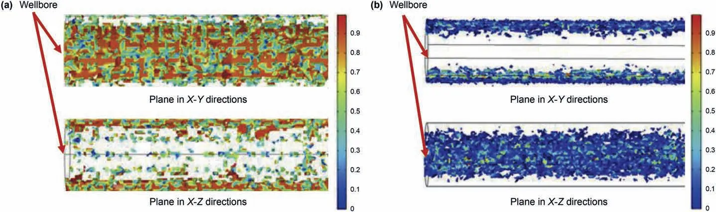
Fig. 3. Initial damage distribution under in-situ stress: (a) distribution of tensile damage; (b) distribution of shear damage.
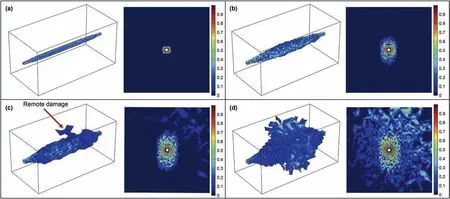
Fig. 4. Damage evolution with CO2 injection at different time: (a) t = 10 s; (b) t = 50 s; (c) t = 100 s; (d) t = 200 s.

Fig.5. The proportion of tensile damage with injection time at different CO2 injection rates.
Fig.6. Variation of damage volume with injection time at a constant CO2 injection rate of 0.05 m/s.
4.4. The influence of injection media
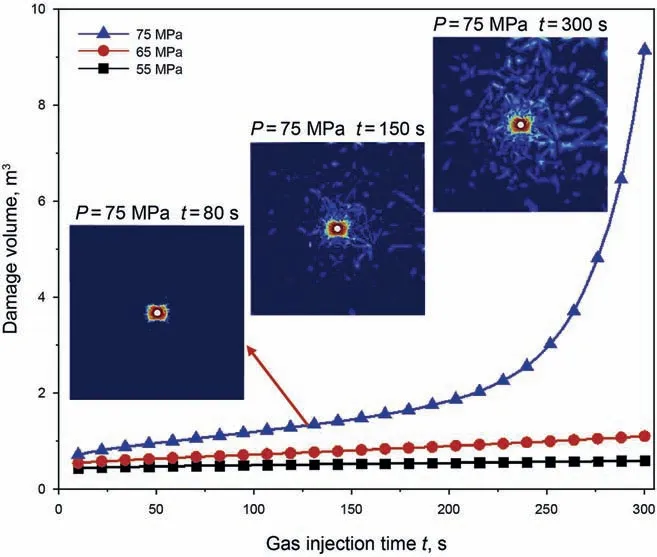
Fig. 8. Variation of damage volume with inection time at different CO2 injection pressures.

Fig.9. Variation of high-effective damage volume with injection time at different CO2 injection pressures.
To explore the effect of different injection media on rock damage, CO2, nitrogen, and water are selected for the simulations.Due to the difference in their properties such as viscosity and density,the injections of three fluids will lead to different damage evolution behavior.

Fig. 7. Damage evolution of reservoir rocks at different CO2 injection pressures: (a) P = 55 MPa; (b) P = 60 MPa; (c) P = 70 MPa; (d) P = 80 MPa.

Fig.10. Damage evolution of rock induced by different injection media: (a) water; (b) nitrogen; (c) carbon dioxide.
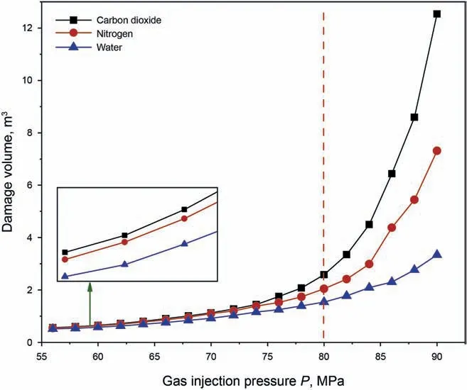
Fig. 11. Variation of rock damage volume with injection pressure and injection medium.
Fig. 10 shows the damaged area induced by the injection of water,nitrogen,and CO2,respectively,with an injection pressure of 80 MPa and an injection time of 200 s. It can be seen that the damaged area of CO2injection is the largest, followed by nitrogen and water. The damage zones caused by water injection are more evenly distributed along the horizontal well in comparison with those caused by nitrogen and CO2injection. This is because water has much lower compressibility than nitrogen and CO2, and the fluid pressure gradient is small, leading to a slower damage expansion. For nitrogen injection, as shown in Fig. 10b, the damaged area extends along both sides of the horizontal well,and sporadic fracture zones appear in the far area.For CO2injection,the damage distribution is similar to that of nitrogen, but the number and range of fracture zones far away from the well are higher than nitrogen injection. The main reason for this phenomenon is the different fluidity of different fluids in porous media. CO2has low viscosity and high energy storage. It flows fastest in the reservoir and can relatively easily reach areas far away from the horizontal well. This will increase the pore pressure and transfer the fluid pressure to more weak points so that the fractured region produced by CO2injection is larger.
Fig.11 shows the variation of rock damage volume with injection pressure and injection medium. It can be seen that when the injection pressure is less than 80 MPa,the relationship between the damage volume and the injection pressure is approximately linear for each injection medium. When the injection pressure is greater than 80 MPa, due to the higher injection pressure, the injected medium is easier to reach the area far away from the horizontal well and transfer the fluid pressure to more rock weak points,resulting in large-scale rock damage, so the damage volume increases exponentially with pressure; the damage volume of CO2injection increases much faster with pressure compared with nitrogen and water. The overall damage volume of CO2injection is always greater than those of nitrogen and water injection, indicating a superior stimulation result of CO2injection.
5. Conclusions
(1) Affected by initial in-situ stress, tensile damage and shear damage are concentrated in the vertical direction and the horizontal maximum compressive principal stress direction of the studied well, respectively. The degree and extent of tensile damage are higher than shear damage.
(2) The highly damaged area induced by high CO2injection rate and injection pressure is mainly concentrated in the vertical direction near the well, i.e., the direction of maximum compressive principal stress. CO2injection promotes the further development of tensile damage but prevents the initiation of shear damage, leading to the transition from shear damage to tensile damage.
(3) Increasing CO2injection pressure can effectively expand the damaged area and obtain a more complex fracture network.High injection pressure causes remote damage at a certain distance far away from the horizontal well; meanwhile, the development of remote damage will inhibit the further development of high damage area near the well.
(4) Under the same injection parameters, CO2is easier,compared with nitrogen and water, to flow into the area far away from the wellbore and generates a highly stressed area due to its low viscosity and high energy storage,resulting in larger damage volume. Thus, CO2is a superior stimulation medium compared with nitrogen and water.
Acknowledgment
The authors are very much indebted to the Projects Supported by the National Science Foundation of China(41972138,52074312),the National Science and Technology Major Project of China(ZD2019-183-007)for the financial support.
杂志排行
Petroleum Science的其它文章
- A fast space-time-domain Gaussian beam migration approach using the dominant frequency approximation
- Predicting gas-bearing distribution using DNN based on multicomponent seismic data: Quality evaluation using structural and fracture factors
- Reflection-based traveltime and waveform inversion with secondorder optimization
- Determination of dynamic capillary effect on two-phase flow in porous media: A perspective from various methods
- Settling behavior of spherical particles in eccentric annulus filled with viscous inelastic fluid
- Laboratory investigation on hydraulic fracture propagation in sandstone-mudstone-shale layers