Three-dimensional coordinates test method with uncertain projectile proximity explosion position based on dynamic seven photoelectric detection screen
2022-09-22HanshanLiXiaoqianZhang
Han-shan Li,Xiao-qian Zhang
School of Electronic and Information Engineering,Xi'an Technological University,Xi'an,710021,China
Keywords:Dynamic multi-screen array plane Flash photoelectric detection target Projectile signal processing Particle swarm Proximity explosion fuze Three-dimensional coordinate
ABSTRACT To objectively obtain the three-dimensional coordinates of the projectile fuze proximity explosion when projectile intersects the head of missile target,we propose a dynamic seven photoelectric detection screen test method,which is made up of six plane detection screens and a flash photoelectric dynamic detection screen.The three-dimensional coordinates calculation model of the projectile proximity explosion position based on seven plane detection screens with dynamic characteristics is established.According to the relation of the dynamic seven photoelectric detection screen planes and the time values,the analytical function of the projectile proximity explosion position parameters under non-linear motion is derived.The projectile signal filtering method based on discrete wavelet transform is explored in this work.Additionally,the projectile signal recognition algorithm using an improved particle swarm is proposed.Based on the characteristics of the time duration and the signal peak error for the projectile passing through the detection screen,the signals attribution of the same projectile passing through six detection screens are analyzed for obtaining precise time values of the same projectile passing through the detection screens.On the basis of the projectile fuze proximity explosion test,the linear motion model and the proposed non-linear motion model are used to calculate and compare the same group of projectiles proximity explosion position parameters.The comparison of test results verifies that the proposed test method and calculation model in this work accurately obtain the actual projectile proximity explosion position parameters.
1.Introduction
In the field of gun and weapon development,the changing dynamic parameters of a projectile restrict the gun's performance.These parameters are mainly related to the velocities and dispersion coordinates at initial,middle,and terminal trajectories.Due to the gun barrel vibration and projectile friction in the gun bore during the process of projectile firing,uncertainty exists at the moment when the projectile leaves the gun bore,which leads to uncertainty in the coordinate distribution of the projectile at the middle or terminal trajectory.The technology for measuring dynamic parameters of a flying projectile has always been an important part of weapon shooting range exterior ballistic test,and it is also the research hotspot in weapon performance tests.In the projectile flight parameter measurement research,many national and international experts have proposed relevant test methods,which mainly use non-contact measurement devices.For instance,the authors in Ref.[1]study the double N-type screen array target test device,and derive the two-dimensional coordinates calculation model for the projectiles passing through six detection screens on the premise that the projectile passes through the detection screen area vertically.This model accurately calculates the twodimensional coordinates.The six detection screen intersection test method based on the linear motion of the flying projectile is proposed,and the calculation model of two-dimensionalcoordinates is established.The error distribution is presented by changing the structural parameters of the detection screens.Please note that different factors affect the test error[2,3].Similarly,the coordinate calculation function is given by the spatial geometric relations of the seven detection screens[4].The multiple line lasers intersection test system is composed of the planes emitted by the line lasers.The two-dimensional coordinates calculation model for the projectiles passing through the line laser plane is established in Ref.[5].The double line array CCDs intersect test method is proposed to obtain the two-dimensional coordinates of the flying projectile from the coplanar characteristics of two-line array CCDs intersection.The error distribution of the coordinates is analyzed,and the calculation model of capturing rate using single CCD test method is discussed[6—8].These test devices use different number of detection screens to form intersection test mechanisms,and the field of view of optical lens can be flexibly replaced to form different test target surfaces.
The existing multi-screen intersection test method only considers the two-dimensional coordinates of the flying projectile,and the three-dimensional coordinates of the projectile proximity explosion position cannot be obtained accurately.The proximity explosion position parameters of the projectile fuze with respect to the target are important technical indices to measure the fuze performance.Due to the diversity of intersection attitude between the projectile and target,the projectile proximity position has a random distribution.Therefore,it is difficult to use fixed projectile proximity explosion parameters as fuze explosion control results[9—11].The main factors that result in the random distribution of the projectile proximity explosion position are the projectile initiation control,velocity,projectile direction,velocity,and size of the target under the intersection condition,and so on.The projectile initiation control depends on the energy of the echo obtained by the projectile fuze device at the moment of intersecting the target.This echo energy is not the same in different intersection states[12,13].Different optical test methods were proposed to acquire the proximity parameters of projectile fuze at the time of intersection of projectiles and targets in space.These methods include the camera method[14],complementary test method of six detection screen intersection and a single camera,acoustic target test system,and so on.A method for measuring the position of exploding projectiles by the intersection of two area array cameras was described in Ref.[15].This method is mainly based on the principle of intersection of two area array cameras on the ground.As the projectile is flying at a high velocity,the area array camera needs to have a sufficiently high sampling frequency.At the same time,as this method uses the image of the projectile explosion position,it is difficult to determine the initial position of the projectile explosion because of the large luminous area formed by the projectile explosion.There is an obvious error in extracting the projectile explosion time using a single camera.Furthermore,the height of the projectile proximity explosion position is usually large,e.g.,more than 50 m.It is difficult for the central intersection plane of the two area array cameras to achieve strict coincidence intersection,which causes a certain time difference in the projectile proximity explosion images captured by the two area array cameras,and consequently,the error of the whole test system is larger[16,17].In addition,the six detection screen array uses linear equations-based calculations.For the projectile fired by long-range artillery,the trajectory of the projectile is no longer linear in the intersection area of the projectile and the target.Therefore,the calculation model used in the six detection screen array is not suitable.The acoustic target test method is proposed[18].This system is mainly composed of line array multi-point acoustic sensors.When a projectile explodes,the explosion position is calculated by the time difference between the sound reaching the acoustic sensor device and the location of the known unit acoustic array sensor.In the test,the acoustic array sensors are arranged at the intersection of the projectile and the target.Due to the high projectile position,there is a large time error when the explosion sound information is transmitted to the unit acoustic sensor due to the sound propagation and environmental factors,such as the influence of wind,which increases the measurement error of the test system.A few researchers have improved the layout of the acoustic sensor test system,converting the acoustic array sensor into a linear array model,and arranging it orthogonal to the missile and ballistic targets[19,20].However,due to the complexity of the test site,it is relatively difficult to mount the long strip array acoustic sensor on the missile and ensure its orthogonality.In addition,the signal transmission of the acoustic sensor also restricts this layout method.Due to the unsuitability in practical scenarios and obvious test errors,the existing test systems are not appropriate for determining the coordinates of the projectile explosion position.The non-contact multi-detection screen array intersection test method is easy to realize when the height of the high-altitude explosion position is more than 50 m,thanks to its flexible design,high detection sensitivity and relatively large field of view.At present,it is still the main method for detecting and testing the proximity fuze,where the distance between the launching gun and missile target is generally more than 1500 m.Due to gravity,the trajectory of projectile motion at 1500 m presents a parabolic motion.In addition,the farthest distance of the corresponding detection screen plane is more than 50 m.Therefore,it is not suitable to use the linear motion to calculate the coordinates of the flying projectile passing through the detection screen array.In addition,a single multi-screen array intersection system cannot measure the three-dimensional coordinates of the explosion position for the projectile fuze relative to the attacking missile target.
In order to meet the high precision requirement of measuring the three-dimensional coordinates of the projectile proximity explosion position,in this work,a new multi-screen array test system using six detection screen planes and a flash photoelectric detection sensor is proposed.
2.Method and principle of measuring explosion position coordinate parameters of multiple screen array
We propose a test method for calculating the three-dimensional coordinates of the projectile proximity explosion position.The proposed method is a combination of six detection screens array and a flash photoelectric detection sensor.This is shown in Fig.1.
The multi-screen array test system consists of the detection screens of six photoelectric detection targets,the flash photoelectric detection sensor,and the acquisition and processing device.We denote the six detection screens as G-G.Each detection screen is formed by photoelectric detection target.When the projectile passes through the detection screens G-G,the instant time is represented by t-t,respectively.In order to improve the flexibility and the convenience of the layout of the test equipment in the shooting range,the detection screens G-Gare integrated into a target structure.Similarly,the detection screens G-Gare integrated into another target structure.The distance between the center lines of these two target structures is the target distance layout in the test site denoted as s.Please note that the Gis the detection area of flash photoelectric detection sensor.At the moment of projectile explosion,the flash photoelectric detection sensor detects the firelight signal,and the instant time is recorded as t.At this time the position is denoted as P(x,y,z).It is noteworthy that the time tis dependent on the projectile explosion,and is uncertain.Therefore,P(x,y,z)represents a dynamic coordinate,which is the actual position projectile explosion.Inorder to establish the test model,we consider that the x and y coordinates in P(x,y,z)form the two-dimensional plane,which is regarded as a detection plane xoy.The position of detection plane xoychanges with the time of projectile explosion.Fig.2 presents the schematic diagram of the geometric relationship of the dynamic seven screens array intersection in space,sis the distance between Gand G,sis a dynamic parameters.
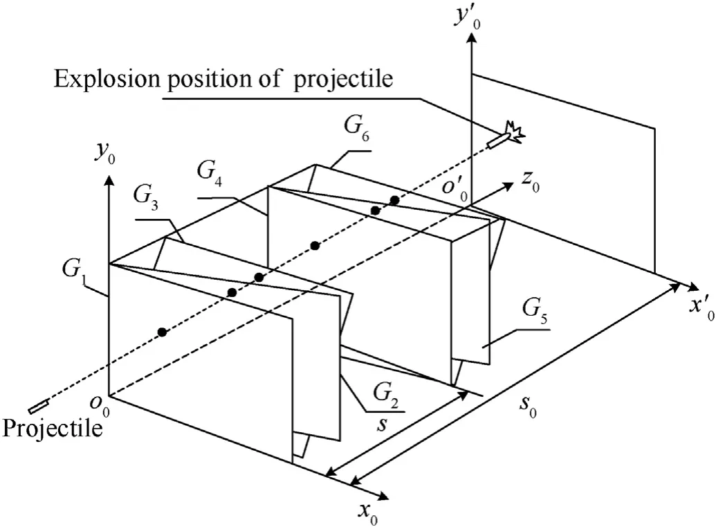
Fig.2.The geometric relationship of the dynamic seven screens array intersection in space.
In the photoelectric detection target of the test system,the detection screen plane is mainly composed of optical lens,slit diaphragm,line array photoelectric detector and processing circuit[21],as presented in Fig.3.In Fig.3,the slit diaphragm is placed at the imaging position of the optical lens,and a detection screen plane with a certain thickness is formed by the slit diaphragm.H denotes the detection distance,i.e.,the object distance,and u denotes the image distance between the photoelectric detection receiver and the lens.When the projectile passes through the detection screens,the transient signal on the sensitive surface of the photoelectric detection receiver is obtained by the projectile imaging principle.After the signals are collected and filtered,and the starting times of the projectile passing through each detection screen are extracted.These specific time values,i.e.,t-t,t-tare an important data for the calculation of projectile explosion position in the test system.
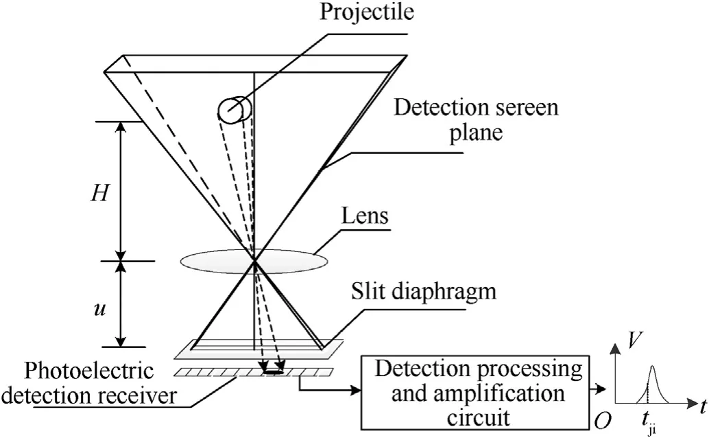
Fig.3.The schematic diagram of the optical detection principle of photoelectric detection target.
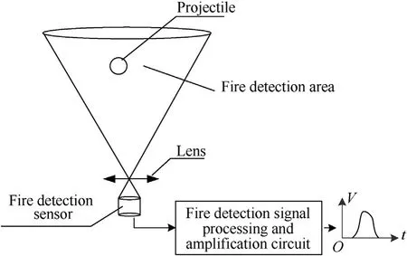
Fig.4.The schematic diagram of detection principle of the flash photoelectric detection target.
The photoelectric detection target is different from the flash photoelectric detection target,and mainly uses the variable luminous flux formed by the projectile passing through its detection screens.The variable luminous flux causes the photoelectric receiver to produce an alternating output signal as the recording time of the projectile passing through the detection screens.The flash photoelectric detection target mainly uses the firelight of the projectile explosion as the detection information.According to the characteristics of the firelight signal,the time of the projectile passing through its detection area is recorded after signal processing.Fig.4 shows the principle of the flash photoelectricdetection target.
In engineering applications,the six screens array and the flash photoelectric detection target are arranged on the ballistic trajectory along the firing direction of the gun according to the arrangement sequence presented in Fig.1.The distance between the detection screen Gof the multi-screen test system and the target projection point is L.The detection screens Gand Gare vertical and parallel to each other and the distance between the detection screens Gand Gis s.This is called the target distance.The distance between the detection screens Gand Gis L.We establish the coordinate system of oxyz.The coordinate system of the detection screen Gis xoy.Please note that the detection screens Gand Gare perpendicular to the horizontal plane xoz.The detection screen Gintersects the detection screen G,and the detection screen Gintersects the detection screen Gat an angle of αand α,respectively.Please note that Gand Gare not perpendicular to xoz.The detection screens Gand G,and Gand Gintersect at an the angles βand β,Gand Gare perpendicular to the plane xoz.The coordinate system oxyz denotes the coordinate system of the missile target and represents the relative translation with respect to the coordinate system oxyz.When the projectile passes through G-G,the projectile explodes in the detection area of the flash photoelectric detection sensor,and the detection screen plane xoyis formed.The instant time values,i.e.,t-t,are obtained for the projectile passing through each detection screen.
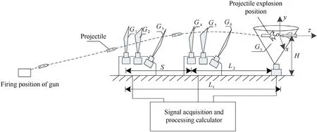
Fig.1.The general design of the proposed dynamic multi-screen array test system.
3.Measurement model and calculation method of the projectile explosion position
According to Figs.1 and 2,the time values t-tof the projectile passing through the detection screens and the moment of projectile explosion are obtained using the high-speed synchronous acquisition method.Considering the influence of projectile's gravity acceleration,air resistance and other factors,and combining with the structural parameters of multi-screen array test system,the calculation model of state parameters of the projectile passing through the multi-detection screen plane in the ballistic terminal test area is constructed.
Assuming that the coordinate position of the projectile passing through the detection screen Gis P(x,y,z)and the velocity of flying projectile is v,the components of the velocity in the coordinate system are v,vand v,respectively.Now,the coordinate positions of the same projectile passing through the detection screens G-Gare expressed as

where,g denotes the deceleration due to gravity and a denotes the deceleration due to air resistance of the projectile.
In conventional weapons,the shape of the projectile's head is generally sharp.Therefore,in Eq.(1),the projectile at high flying velocity is mainly affected by the acceleration due to gravity,and the acceleration due to air resistance can be ignored,i.e.,a=0.Based on this condition,and considering the detection screen Gas the reference plane,we denote A=[x,y,z,v,v,v],the correlation of the six detection screens array plane equations coefficients as B,and the correlation of target layout parameters as C.Then,the coordinates of the projectile passing through the detection screen and the projectile flying velocity satisfy the relation A=B·C.


Using Eqs.(2)and(3),the parameters of A,i.e.,(x,y,z,v,v,v)are obtained.As the projectile explosion coordinates are given in the relative coordinate system oxyz,when the projectile explodes,the time value collected in the detection area Gis given by t,and sis the distance from the explosion position plane to G.At t,the coordinate(x,y,z)is obtained in the plane xoy,as given in:

Relative to the missile target coordinate system oxyz,the coordinates of the projectile explosion position are as follows:

In order to accurately obtain the three-dimensional coordinate parameters in engineering applications,the most influential factors include the time accuracy of the projectile passing through the detection screens,the target distance of the layout test system and the inherent parameters of detection screen planes of test system.The uncertainty in these parameters affects the measurement error of the test system.To the dynamic multi-screen array test system,if we want to get the real data of the projectile explosion,every photoelectric detection sensor must capture the projectile information,this is the prerequisite for our design of the test system.So,it is necessary to obtain the information of the projectile in each photoelectric detection sensor to calculate the result of threedimensional coordinates of the projectile fuze explosion.For thetest system,the experiment of flying projectile explosion test is carried out in the field,and the change of environmental illuminance affects the detection performance of the photoelectric detection sensor,and may introduce external interference signals,this is inevitable.To dynamic seven photoelectric detection screen test system,the detection plane of each photoelectric detection sensor have a certain spatial relationship,when the projectile passes through the seven photoelectric detection screen planes,the flight time of the projectile between the two photoelectric detection screen planes is related to the geometric relationship between them.If the interference signal exists,we can use the time combination between the output target signals of the photoelectric detection sensor,combined with the theoretical flight speed of the projectile,to judge whether the selected target signal is correct at the time,that is,to eliminate the interference signal,we use the time value between the projectile passing through the seven photoelectric detection planes and the inherent spatial geometric relationship of the two planes are judged whether the selected moment signal is correct in each photoelectric detection sensor.
4.Filtering and recognition of the signal processing of projectile passing through detection screen
4.1.Wavelet filtering algorithm of the signal of projectile passing through detecting screen
The multi-screen array test system mainly adopts the photoelectric detection principle based on natural light.The obvious contrast between the characteristics of the projectile and the background luminance is the premise for recognizing the actual projectile signal.The photoelectric detection target is affected by different degrees of strong background luminance.As a result,the signals of the projectile and the interference appear at the same time,thus making it difficult for the photoelectric detection target to recognize the actual projectile signal.In this work,the filtering method of projectile signal is proposed based on the discrete wavelet transform.
Assuming that the output signal of the single detection screen contains the projectile's signal and noise,we express f(t)as

where,y(t)represents the signal of projectile without noise and s(t)represents the noise.The wavelet transform of f(t)is expressed as follows:


Based on the wavelet reconstruction function,the output signal of the projectile is decomposed into 6 layers by using Daubechies wavelet.The 6-th layer low frequency smooth signal Kis observed and we denote Kas 0.The G-Greconstructed signals are divided into the 1—6 layer detail signals.The high frequency component of the output projectile signal is obtained.In order to eliminate the high frequency components from the output projectile signal,w,which are the wavelet coefficients of the output projectile signal,are divided into two parts.The first part is the wavelet coefficients y,representing the projectile signal and second is the wavelet coefficients s,representing the noise.So,w=y+s.The wavelet threshold method is used to remove the noise.It is noteworthy that the Daubechies wavelet basis is selected to decompose the signal into one layer[23].Consequently,a set of wavelet coefficients w(j,k)is obtained.

Similarly,the wavelet filtering processing method is used to process the firelight signal collected by the flash photoelectric detection sensor after projectile explosion.Based on the firelight signal collected by the flash photoelectric detection sensor as presented in Fig.4,the scale factor is adjusted appropriately on the basis of orthogonal wavelet decomposition,signal wavelet reconstruction,and wavelet threshold high frequency noise filtering processing.Fig.7 shows the firelight signal filtering result of the flash photoelectric detection target after projectile explosion.
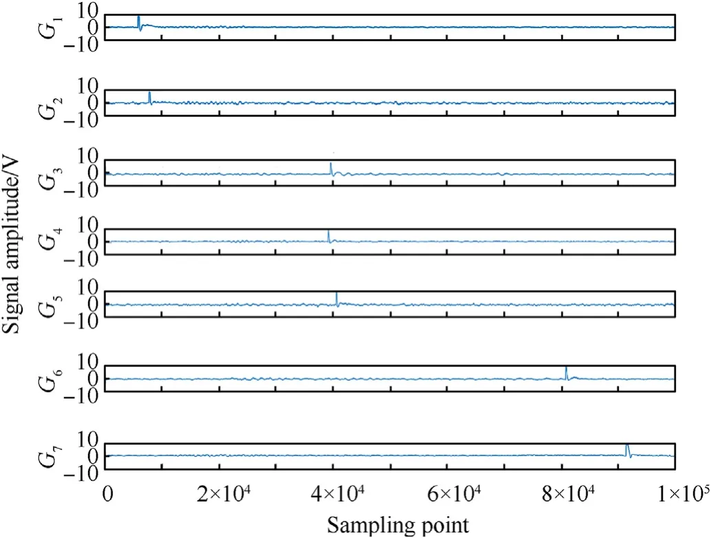
Fig.5.The original signals collected by the test system.
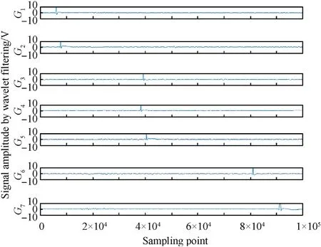
Fig.6.The seven signals of the projectile passing through the detection screens processed by wavelet filtering.

Fig.7.The firelight signal filtering result of the flash photoelectric detection target after projectile explosion.
4.2.Recognition algorithm and time extraction method of the signal of the projectile passing through detecting screen
Because of the complexity of the test environment,it is hard to avoid the interference of the environment.Based on the signal filtering results of the wavelet transform method,this work proposes an improved particle swarm optimization algorithm to recognize the projectile signal.The main steps of the projectile signal recognition algorithm are as follows.
1)The discrete signals of projectile passing through the detection screen are used as the input layer of particle swarm.The particle swarm is initialized,i.e.,g~ particles are generated randomly in the solution space.The positions of the particles are recorded as z={z,z,…,z},and the fitness value of each particle is calculated by utilizing the objective function[24,25].Then,the particles continuously adjust their positions in the solution space to search for a new solution.In each iteration,each particle is adjusted based on two values.First,the optimal position of the particle,i.e.,p.Second,the optimal position of the whole population,i.e.,p.
2)The velocity of each particle is v={v,v,…,v}.After two optimal solutions are obtained,each particle updates its velocity according to(9).

where,v(t+1)represents the velocity of the h-th particle in the jth dimension at t+1 iteration,ω denotes the inertia weight,cand cdenote the acceleration constant,rand rdenote the random numbers in the interval(0~1),and r=r=0˙2.We set the upper limit on the velocity in order to avoid the high velocity of the particle.When v(t+1)>v,we consider v(t+1)=vand when v(t+1)<-v,we consider v(t+1)=-v.


When the inertia weight is determined,it is used as the initial value of Levenberg-Marquardt.The projectile signal is recognized by the LM algorithm.First,the neural network is trained with PSO,the position vector zof particle swarm is defined,all the connection weights,thresholds of BP network and the position vector zare initialized.Then,the improved particle swarm optimization algorithm is used to search the optimal position,and the minimum fitness value is calculated,then

where,trepresents the objective value,εrepresents the calculated value,mdenotes the number of training samples,and mrepresents the number of output nodes[27].
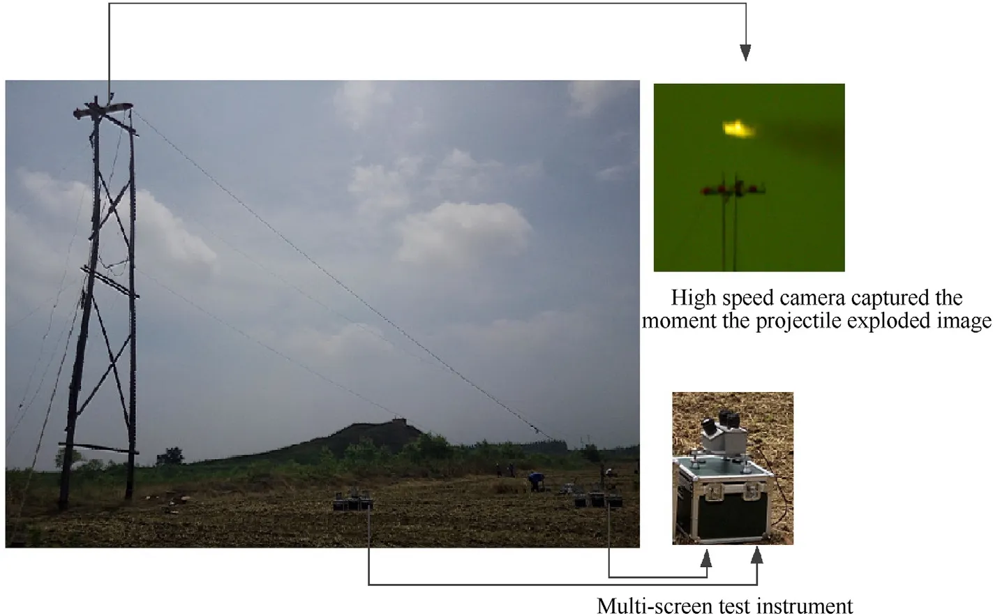
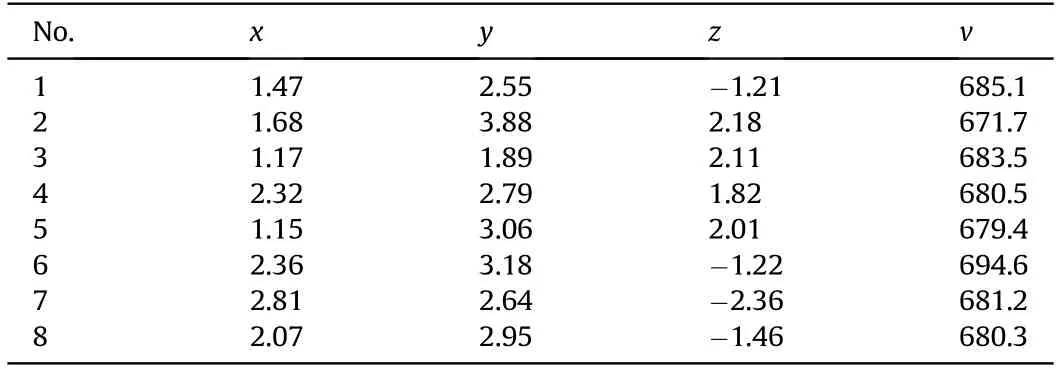
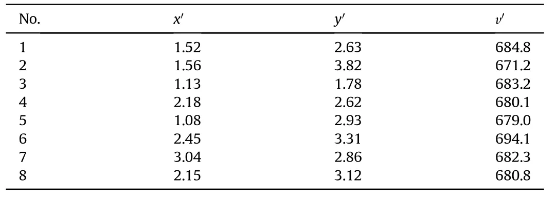
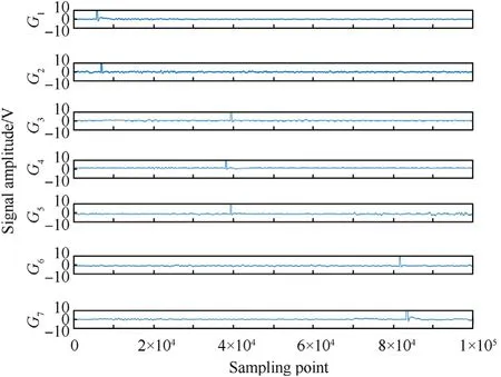
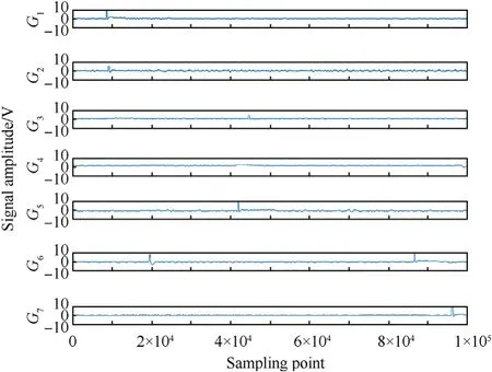
4)The parameters of the PSO algorithm are set as follows:the range of velocity of particle is(20—120),the inertia weights ω=0˙15,ω=0˙85,and ω=0˙5.The acceleration constants are c=c=1˙56.The sample zis used and the network is established by initializing the network weights and thresholds are optimized using Eq.(9).The structure of the BP network is 3-7-3.The input value is one-dimensional vector.After singular value feature extraction of projectile transient characteristics,the resultant length is 3.The output value is onedimensional dimensionless vector with normalized value between 0.1 and 0.9.We calculate the actual output f,and then calculate the error σ by using Eq.(11).If σ Based on the particle swarm optimization algorithm processing and the given threshold of signal,the sample points of the signal ofthe projectile passing through each detection screen are greater than the given threshold.The width and peak value of the projectile signal are calculated.For the same projectile signal,the output signals of six photoelectric detection targets are similar,and the results are verified by the error in the width and the peak value of the six projectile signals.In the test system,the sampling frequency of the acquisition and processing device is 2 M,so the error in the time width of the projectile signal of the test system is not more than 0.01 μs.As presented in Fig.1,the detection screens Gand Gare orthogonal to the projectile trajectory,the intersection angles of the detection screens Gand G,Gand Gare αand β,respectively.The intersection angles of the detection screens Gand G,Gand Gare αand β,respectively.The error in the output signals of two detection screens is dependent on the cosine function of the intersection angles of two detection screens,i.e.,cos αand cos α,or cos βand cos β.In the proposed test system design,α=α=˙24˙5,β=β=˙22˙8.So,the error range between the peak values of the signals of same projectile passing through the detection screen Gand other inclined detection screens is less than 0.09 times the signal of projectile.The width and the peak value of the signals of projectile passing through six detection screens are denoted by T and V.By distinguishing T and V,the false projectile signal is eliminated and the purpose of six channel signal recognition is achieved.Considering the example of signal waveforms of the projectile passing through the detection screens,Fig.8 shows the waveforms collected and filtered by the detection screens Gand G.udenotes the selected threshold.By considering the maximum value of the acquired signal and combining it with the acquisition time sequence,the first time value is greater than uobtained by particle swarm search method.We denote the first time index as nand the time at which the signal has a maximum value as n,and nas the time index where the signal peak value of the projectile drops just more than u.When the projectile starts to leave the detection screen,the time duration of the projectile passing through the detection screen is T=(n-n)/f,where fdenotes the sampling frequency.The time duration of the projectile passing through the detection screen Gand Gis calculated to be 0.12 ms and 0.13 ms,respectively.At the same time,the amplitudes of the signals peak values are 11.2 V and 11.17 V,respectively.The same projectile can be analyzed on the basis of time duration and signal peak value.Similarly,the same method is used to recognize the output signal u collected by the flash photoelectric detection sensor.When the flash photoelectric detection sensor captures the instantaneous signal after the projectile explosion,the instantaneous signal is mainly composed of the firelight signal.Because the difference between the firelight signal and the interference signal is obvious,the firelight signal belongs to the bright signal.When the firelight is generated at the moment of the projectile fuze explosion,it is relatively strong.The time value at which the firelight signal amplitude is greater than the background noise amplitude,which is recorded as the starting point,the threshold of signal is set to u.When u>1˙5u,the corresponding time value of the sampling point is used as the extraction time value of the projectile explosion firelight signal.As shown in Fig.10,the threshold u=1˙8V.By discriminating the signal amplitude corresponding to the sampling point and selecting the corresponding time value of u=u=1˙8V as the starting time nof the firelight signal,the starting time value of the firelight signal after projectile explosion t=45˙824ms. Fig.8.The waveforms collected and filtered by detection screens G1 and G2. Based on the signals of the projectile passing through the six detection screens presented in Fig.5,the time width,amplitude,and starting time value of each projectile passing through the detection screens is obtained.These parameters provide useful information in analyzing if the detected signals are the consequence of the same projectile.Due to the inconsistency of projectile charge,the firelight pulse width value of flash photoelectric detection sensor is in an uncertain state.Therefore,the firelight signal collected by the flash photoelectric detection sensor is directly obtained according to the extraction time values method as presented in Fig.9. The photoelectric detection target of dynamic seven screens array test system consist of highly sensitive photoelectric detection receivers,optical lens,slit aperture and detection processing circuit.The optical lens has a fixed focus mode with a focal length of 85 mm and an aperture of 1:1.8.The response wavelength of the photoelectric detection receiver is between 0.38—1.0 μm.Its response time and slit aperture are less than 10s,and 0.3 mm×43 mm,respectively.Based on the design parameters,the six detection screen planes can form a 24detection field of view with a detection capability of 1200 times the diameter of the projectile.The flash photoelectric detection sensor uses a photosensitive element of high-sensitivity and small-size as the fuze explosion firelight capture detector.Its peak response wavelength is 720 nm,and the optical lens uses a zoom lens with a focal length between 50 mm—135 mm.The geometric parameters used in the six detection screen planes are α=α=24˙5and β=β=22˙8.Based on the designed multi-screen array test system,a proximity fuze with live ammunition is used to evaluate the effectiveness and scientific validity of the test model.The linear motion model is compared with the non-linear motion model proposed in this work.The linear motion model for six screen intersection test system is detailed in Ref.[28].At the same time,a high-speed camera is arranged on the orthogonal side of the missile model projection position,which captures the fuze explosion image and uses it to determine the two-dimensional coordinates(y,z)of the measurement direction,and compares it with the coordinates(y,z)of multi-screen array test system.For the linear projectile motion model,the coordinates and velocity are recorded as(x,y)and v,respectively.For the non-linear projectile motion model,the coordinates and velocity are recorded as(x,y,z)and v,respectively.An image of the test site layout and a projectile explosion captured by using a high-speed camera are shown in Fig.10. Fig.9.The schematic diagram of firelight signal extraction after the projectile explosion. Fig.10.The test site layout and a projectile explosion image captured by high-speed camera. In Fig.10,the target distance of the multi-screen array test system is 10.8 m,i.e.,s=˙10˙8m,and the distance between the center of the multi-screen array test system and the target projection position is L=˙27˙5m.Then,L=˙14˙7m,and the height of the missile model is equal to 22.7 m.Based on the signals of the projectile passing through the multi-screen area presented in Fig.5,the proposed wavelet filtering,improved particle swarm recognition,and time value extraction algorithm are used to process the signals.Table 1 shows the time values of the projectile passing through each detection screen corresponding to the signal waveforms presented in Fig.5. Considering the structural parameters of the test system,we denote the correlation of six screen array plane equations coefficients as B,and the correlation of target layout parameters as C.By combining(1),(4),and(5),the calculation results are x=1˙65m,y=2˙35m,z=1˙56m,γ=3˙65θ=1˙09,and v=˙682˙5m/s. As presented in Table 1,the linear motion model of the projectile is used to calculate the projectile proximity explosion position parameters.Please note that(12)denotes the linear motion model. Table 1Time values of projectile passing through each detection screen. According to Eq.(12),the calculation results using linear motion model are x=1˙62my=2˙26mγ=4˙69θ=3˙37,and v=˙684˙4m/s.The coordinate data of image acquired by high-speed camera arey=2˙38m,and z=1˙58m.Since the projectile explosion image acquired by using a high-speed camera belongs to the actual test situation,the two-dimensional coordinates of projectile explosion position in y and z directions are calculated by using the proportional relationship between the number of pixels formed by the size of the simulated target in the image and thenumber of pixels of the projectile explosion position relative to the head of the simulated target.The calculation method is presented in Ref.[15].It is noteworthy that the influence of other factors on high-speed camera for the test data is not considered.The comparison shows that the errors in the coordinates of y and z directions calculated by the non-linear motion model and the highspeed camera areΔy=y-y=-0˙03m,Δz=z-z=-0˙02m.The errors in the coordinates of x and y directions calculated by the non-linear motion model and linear motion model are Δx=x-x=0˙03mΔy=y-y=0˙09m,respectively.By comparing the error in y direction,it is obvious that the results calculated by the non-linear motion model are closer to the results of the high-speed camera,which reflects that the test data using non-linear motion model better reflects the actual projectile proximity explosion position. In order to further verify the superiority of the non-linear motion model,we collect a group test data of 8 projectiles explosions.The original signals of the first and second projectiles passing through the six detection screens area and the flash photoelectric detection sensor are presented in Fig.11 and Fig.12. Table 2 shows the calculated coordinate data of the projectile explosion position obtained using the non-linear motion model.Table 3 shows the calculated coordinate data of the projectile explosion position obtained using the linear motion model.Table 4 shows the calculated coordinate data of the side direction of the projectile explosion position acquired using the high-speed camera and image processing.The coordinate errors of Tables 2 and 3,Tables 2 and 4 are(Δx,Δy)and(Δy,Δz),respectively. By comparing the data in Tables 2 and 3,the average errors between the coordinate data calculated by the linear and nonlinear motion models are obtained asΔx=0˙10m,Δy=0˙13m.Comparing the data of Tables 2 and 4,the average errors in the y and z directions areΔy=0˙026m andΔz=0˙021m,respectively.On the basis of data comparison,the average error between the results calculated using the linear model and the actual projectile explosion position obtained using the high-speed camera is obviously large.However,the average error between the results calculated using the non-linear motion model and the actual projectile explosion position is smaller.This reflects that the traditional linear motion model cannot consider the influence of gravity acceleration during the projectile's flight.At the same time,the linear motion model does not introduce a flash photoelectric detection sensor to obtain the time value of the projectile explosion.So,the coordinates of the projectile explosion position in z direction cannot be obtained.The new test system composed of six detection screens and flash photoelectric detection sensor proposed in this work is effective and efficient.The errors between the data in Tables 2 and 4 lead to two main observations:On the one hand,it is confirmed that there are random factors in the field layout,due to which the requirements of the multi-screen array test system for astrictly predefined trajectory cannot be met.On the other hand,it shows that there are errors in the spatial geometric relationship of the multi-screen screen array.Thus,the non-linear motion model still gives a slightly different position compared with the actual projectile explosion position.However,overall,the calculation method effectively improves and enhances the accuracy of the whole test system. Table 2The calculated coordinate data of the projectile explosion position obtained using the non-linear motion model. Table 3The calculated coordinate data of the projectile explosion position obtained using the linear motion model. Table 4The calculated coordinate data of the side direction of the projectile explosion position acquired using the high-speed.camera and image processing. Fig.11.The original signals of the first projectile passing through the detection screens and projectile explosion area. Fig.12.The original signals of the second projectiles passing through the detection screens and projectile explosion area. In this work,this limitation is overcome.According to multiple screen plane equations and the projectile's own gravity acceleration,a test model of projectile proximity explosion position is established under the uncertain state of random dispersion of flying projectiles.The parameter function of projectile proximity position under a variable curve motion is derived.The theoretical calculation method proposed in this work is in line with the test requirements of dynamic projectile parameters in the current range weapon and has the ability to obtain the projectile proximity explosion data for the projectile fuze to the space target with high precision.The proposed method allows to overcome the defects of the traditional methods based on the linear motion of the projectile.At the same time,the flash photoelectric detection sensor is skillfully introduced to obtain the time value of the projectile explosion.The test model of the projectile explosion position obtained by using the non-linear motion is established based on the mechanism of multi-screen array dynamic combination.In addition,it is not hard to find that this method uses the traditional mode of six screens intersection test principle,which can test the projectile's flight speed,coordinates and azimuth angle.We introduces a flash photoelectric detection sensor to capture the moment of the projectile's explosion,and establishes a three-dimensional coordinate calculation model of projectile explosion under non-linear motion state of the projectile.So,this testing system also can measure the conventional bullet flight parameters.The difference between the test system we designed and the traditional test system is that the flash photoelectric detection sensor is introduced to form a new test mechanism.At the same time,the calculation model established is based on the influence of the projectile's own gravity,which avoids the flight speed attenuation of projectile caused by the long-distance movement,the influence of attenuation and gravitational acceleration factors makes the measurement results produce obvious errors in traditional test system.The test method and calculation model studied in this work are innovative and have the capability to solve the problem that the traditional test system face,i.e.,the inability to obtain the actual three-dimensional coordinates of the projectile explosion position. In this work,a multi-screen array test method consisting of six detection screen planes and one flash photoelectric detection sensor is proposed to obtain three-dimensional coordinate parameters of the projectile explosion position with respect to a missile target.The particle motion equations of seven detection screen planes with dynamic characteristics are established.The three-dimensional coordinate test model of the projectile explosion position is derived,which is related to the inherent structural parameters of the multi-screen array,the gravity parameters of the projectile,and the layout parameters of the test system.According to the characteristics of the collected signals of the projectiles passing through the detection screens,the signal filtering method based on discrete wavelet transform and the improved particle swarm projectile signal recognition algorithm are explored.The efficiency criterion relies on the two angles of the time width and peak error of the signals of projectile passing through detection screens.By filtering and recognizing the collected signals of the projectile,combined with actual experimental tests,the test models of the linear motion and non-linear motion of the projectile are used to calculate the error of the projectile flight parameters.The high-speed camera method is introduced and the projectile explosion position parameters are calculated based on the acquired side image of the projectile explosion.The calculation results of the three test methods are comprehensively compared,the calculation model of the projectile explosion position by using non-linear motion established in this work obtains the three-dimensional coordinates of the projectile explosion position,and the error is less than other test methods.The results verify that the proposed test method is correct and scientific. This work has been supported by Project of the National Natural Science Foundation of China(No.62073256,61773305),the Key Science and Technology Program of Shaanxi Province(No.2020GY-125)and Xi'an Science and Technology Innovation talent service enterprise project(No.2020KJRC0041). The authors declare that they have no known competing financial interests or personal relationships that could have appeared to influence the work reported in this paper.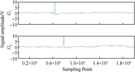
5.Experiment and analysis




6.Conclusions
杂志排行
Defence Technology的其它文章
- 3D laser scanning strategy based on cascaded deep neural network
- Damage analysis of POZD coated square reinforced concrete slab under contact blast
- Autonomous maneuver decision-making for a UCAV in short-range aerial combat based on an MS-DDQN algorithm
- The properties of Sn—Zn—Al—La fusible alloy for mitigation devices of solid propellant rocket motors
- The surface activation of boron to improve ignition and combustion characteristic
- Numerical investigation on free air blast loads generated from centerinitiated cylindrical charges with varied aspect ratio in arbitrary orientation
