Resistance of grid steel-tube-confined concrete targets against projectile impact:Experimental investigation and analytical engineering model
2022-09-22DinyiSongQinghuTnChomeiMengYiminHungYngyueyeCoZhigngJing
Din-yi Song ,Qing-hu Tn ,Cho-mei Meng ,Yi-min Hung ,Yng-yueye Co ,Zhi-gng Jing
a Undergraduate School,National University of Defense Technology,Changsha,410072,PR China
b College of Aerospace Science and Engineering,National University of Defense Technology,Changsha,410073,PR China
c College of Aerospace Engineering,Air Force Engineering University,Xi'an,710038,PR China
Keywords:Penetration mechanics Grid structural system Steel-tube-confined concrete(STCC)targets Armor piercing projectile(APP)Depth of penetration(DOP)Finite spherical cavity expansion(FSCE)
ABSTRACT Steel-tube-confined concrete(STCC)targets are provided with excellent anti-penetration performance over semi-infinite concrete(SIC)targets since the steel tube imposes passive restraint on the in-filled concrete during the penetration process.Grid STCC system with square steel tubes is a potential solution to protective structures.In this paper,experiments of 9-cell grid STCC targets penetrated by 12.7 mm Armor Piercing Projectile(APP)were performed.The influence of side length and thickness of steel tube,steel ratio and impact velocity on anti-penetration performance were taken into account.Additionally,single-cell square STCC targets were also designed and tested for comparison with the 9-cell grid STCC targets.Damage modes and parameters of the tested targets were measured and discussed.Moreover,the stiffness of radial confinement of grid STCC targets is achieved according to the elastic solution of infinite cylindrical shell in Winkler medium.Furthermore,the penetration resistance and depth of penetration(DOP)for grid STCC targets are obtained on the basis of the dynamic finite spherical cavityexpansion(FSCE)models including radial confinement effect.It is shown that the 9-cell grid STCC targets with optimal dimension match of thickness and side length of steel tube can reduce the DOP by about 17%and 23%in comparison with the SIC targets and single-cell square STCC targets,respectively,due to both the confinement of square steel tube to concrete in the impacted cell and the additional confinement of the surrounding cells to the impacted cell;the penetration resistance and DOP of the grid and cellular STCC targets with similar steel ratio is close,and thus the grid STCC targets with simpler manufacturing process and excellent in-plane expandability are preferred in engineering practice;moreover,the predicted results of DOP model based on the FSCE models agree well with the tested results with the maximum disparity less than 12%and the proposed model is more applicable to the grid and cellular STCC targets with high radial confinement.
1.Introduction
Concrete protective structures,e.g.,protective walls of nuclear power plants[1—3],may be seriously damaged under the penetration of projectiles,which influences the safety and durability of the structures.The anti-penetration performance of concrete can be greatly improved by not only enhancing performance of concrete but also adopting composite structures.Reinforced concrete[4],high performance concrete[5—9],fiber-reinforced polymer wraps[10],"steel—concrete—steel"sandwiched structures[11],PRP-tube-confined concrete structures[12],concrete-filled steel tubular structures[13,14]and steel-tube-confined concrete(STCC)structures[15,16]are commonly used ways to improve strength,ductility and toughness of concrete.Among them,STCC structures have a great potential.Compared with semi-infinite concrete(SIC)targets,STCC targets show excellent anti-penetration performanceas the steel tube exerts lateral confinement on the in-filled concrete and the strength,ductility and toughness of the in-filled concrete are improved.As confirmed in the previous studies[15—18],depth of penetration(DOP)of the STCC targets with circular crosssections penetrated by 12.7 mm Armor Piercing Projectile(APP)is 10—20%smaller than that of the SIC targets,and the STCC targets also have excellent anti-penetration performance under multi-hit of projectiles.
For practical engineering,the STCC protection structure is usually composed of many structural cells and the impacted cell is confined by the surrounding cells.Therefore,the combination types of cells should be taken into consideration.The penetration tests of a bio-inspired cellular cement targets conducted by Choon et al.[19]shows that compared with the single-cell targets,the front surface spalling of the assembled 7-cell cement targets with the joint gap of air and flexible absorbing material is reduced by 18—26 % and 32—33 %,respectively.Nevertheless,their design of the composite targets failed to fully utilize the confinement of the surrounding cells,and the DOP of the 7-cell cement targets increased by about 10—12%in comparison to the single-cell targets,which shows the significance to properly design the composite STCC targets to take advantages of the confinement effect.During the penetration process,concrete of the impacted cell is influenced by three types of confinement effect,i.e.,the self-confinement of concrete,the confinement of steel tube of the impacted cell and the confinement of the surrounding cells[20].These three types of confinement effect are nonlinearly correlated with dimensions of the steel tube,indicating that there is an optimal dimension match for the composite STCC targets.Song et al.[20]accounted for the confinement effect and designed cellular STCC targets with welded 7-cell hexagonal steel tube.The penetration tests show that under the optimal dimension match,the volume of crater(VOC)and DOP of the cellular STCC targets were 67.9 % and 19.4 % reduced in comparison to the SIC targets,respectively;and as a result of the confinement of the surrounding cells,the VOC and DOP of the cellular STCC targets were 38.6 % and 22.8 % smaller than those of the single-cell hexagonal STCC targets,respectively.
The cross-sectional profile can also significantly influence the confinement effect and the anti-penetration performance of the STCC target.For example,Meng et al.[18]performed penetration tests of single-cell STCC targets with different cross-sectional profiles,namely a hexagon with a side length of 80.5 mm,a square with a side length of 151 mm and a circle with an outer diameter of 140 mm.The results show that the DOP of the hexagonal STCC targets with a steel ratio of 9.75%is about 10.5%smaller than that of the circular STCC targets with the same steel ratio,while DOP of the square STCC targets with a steel ratio of 9.06 % is about 3.5 %larger than that of the circular STCC targets.In spite of this study on single-cell STCC,insufficient research can be found in open literatures about the influence of cross-sectional profile on the resistance of composite STCC targets,i.e.,most penetration experiments were performed with hexagonal STCC targets[20].Moreover,the crosssectional profile also affects the production and construction processes of the composite STCC targets.For instance,compared with square steel tubes,the welding process of hexagonal steel tubes is much more complicated and the size deviation is easy to be accumulated during the welding process.It is also more convenient to use square steel tubes to form grid structures with a regular shape and straight edges,which are more practical in constructions.In addition,grid STCC targets with square steel tubes,as shown in Fig.1(a)and(b),are expected to have a better in-plane expandability and reliable quality when their anti-penetration performance is similar to that of the cellular STCC targets using hexagonal steel tubes.
DOP and penetration resistance are key parameters to characterize the anti-penetration performance of thick targets,and cavity expansion theory is a commonly used method to calculate the penetration resistance and establish DOP prediction formula[21].Forrestal et al.[22—24]and Frew DJ et al.[25]established the cavity expansion theory for SIC targets,and the semi-theoretical and semi-empirical DOP formula was proposed for SIC targets penetrated by the oval-shaped rigid projectiles.Li and Chen[26,27]extended the models developed by Forrestal et al.[22—24]and Frew DJ et al.[25]to apply to general penetration problems of SIC targets by introducing the warhead shape function.Moreover,the effect of compressibility[28,29],strain-hardening[28,29,31]strainrate[28,32]and shear dilatancy[30]of targets material are included in the dynamic cavity expansion theory model to predict the penetration resistance of the SIC targets.However,the results for finite targets are limited,in which influence of free-surface is included without taking confinement into account.Macek and Duffey[33]established finite spherical cavity expansion(FSCE)models of projectiles penetrating into geologic media to capture free-surface and layering effects.Warren et al.[34,35]and Fang et al.[36]also proposed FSCE models to account for the free-surface effect to account for the effect of free-surface on penetration resistance.Zhen et al.[37]established a finite cylindrical cavity expansion(FCCE)theory of compressible material.Despite the numerous researches on finite or semi-finite targets,few studies have been performed on STCC targets.Considering the tube confinement as radial elastic constraints,Meng et al.[38]established the dynamic FSCE theory and developed the corresponding DOP model for STCC targets.The results show that the penetration resistance can be effectively improved by increasing the confinement stiffness within a certain range,and the results of the DOP model agreed well with the tested DOP with a maximum disparity below 8.4 %[16].However,this model is mainly applicable to single-cell STCC targets with low radial confinement,and it is not suitable for the composite STCC targets with high radial confinement.
In this paper,9-cell grid STCC targets are designed and penetrated by 12.7 mm APP,as shown in Fig.1(b).The side length and thickness of the steel tube are considered in the study,as well as the impact velocity.The typical damage modes and parameters of the composite STCC targets are obtained and discussed.Additionally,the tested results of the 9-cell grid STCC targets are compared with those of the SIC targets and the single-cell square STCC targets,as shown in Fig.1(c).In order to analyze the effects of cross-sectional profile on the penetration resistance of composite STCC,the obtained results are also compared with those of 7-cell cellular STCC targets in Ref.[20].Moreover,the dynamic FSCE models reported by Meng et al.[38]are extended to calculate the penetration resistance and the DOP for the grid and cellular STCC targets with high radial confinement.The radial confinement stiffness is achieved by introducing the elastic solution of infinite cylindrical shell in Winkler medium.Finally,the feasibility and rationality of the extended models are validated with the tested results.
2.Brief descriptions of penetration experiments
2.1.Test set-ups and projectiles
Penetration test set-ups are shown in Fig.2,which is the same as those in Refs.[15—18,20].12.7 mm caliber ballistic gun was used to launch 12.7 mm projectiles.Velocity measurement device consists of two light curtain targets and a six-channel electronic time measuring instrument.Horizontal distance between the two light curtain targets is 2 m.The six-channel electronic time measuring instrument measures the time that the projectile passes through the two light curtain targets.The average velocity is approximatelyselected as the impact velocity of the projectile.The high-speed camera system is used to record the impact posture of the projectile.The frame rate used in this test was 50,000 frames per second.The tested targets were held up by steel bracket and covered with sand bags around.
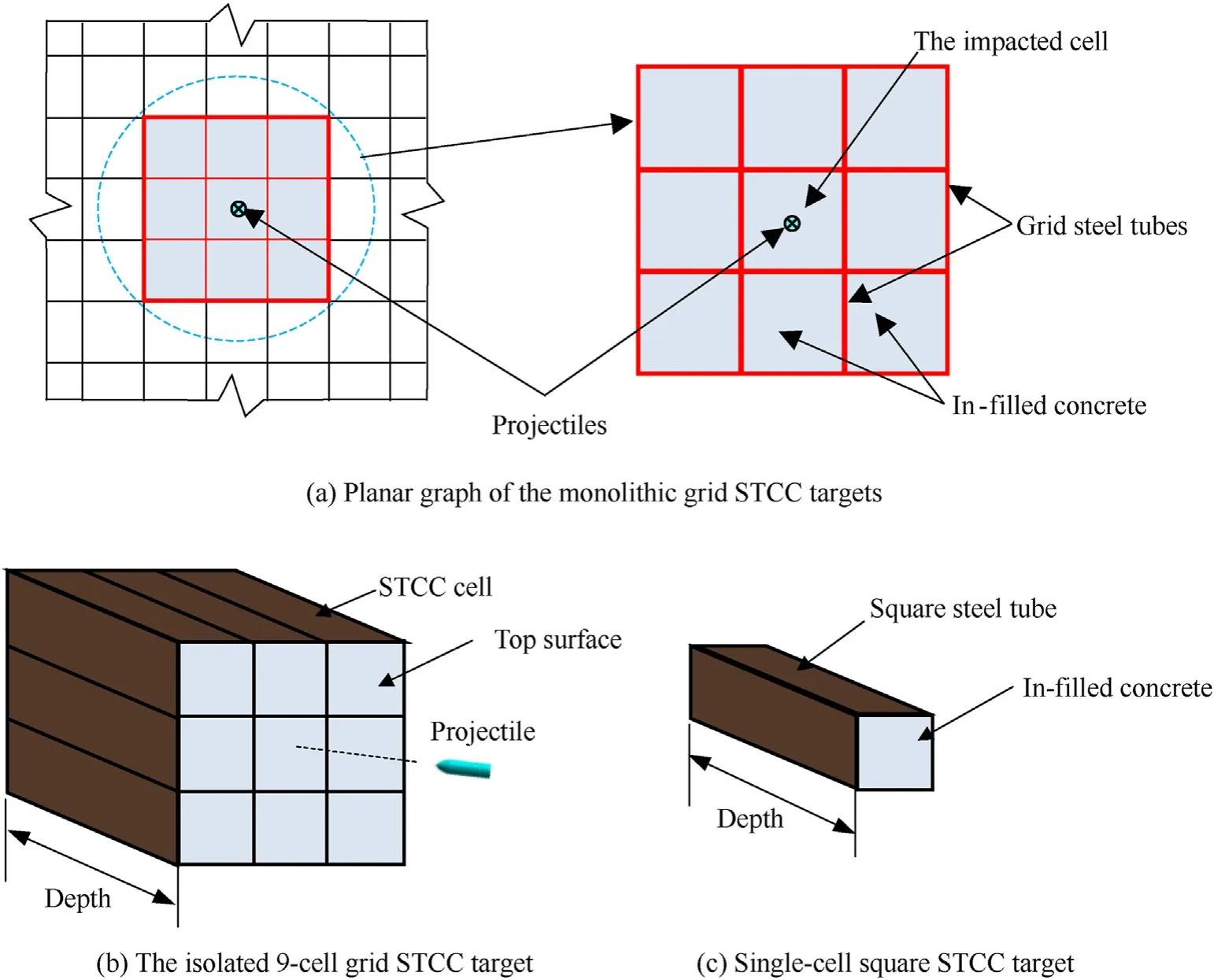
Fig.1.The grid STCC systems.
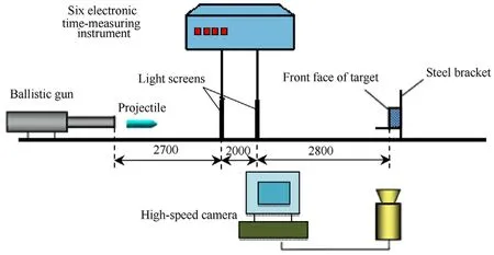
Fig.2.Layout of the test set-ups(units:mm).
The 12.7 mm APP is shown in Fig.3(a),where the hard core is a high-strength alloy cylinder.The warhead is double conical nose and the dimension details are shown in Fig.3(b).Generally,the initial exiting gun velocity of a standard APP is about 800 m/s at ambient temperature,and the velocity can be adjusted by changing the charge or temperature.The projectiles are designed with normal incidence and the impact points are at the center of thetargets.
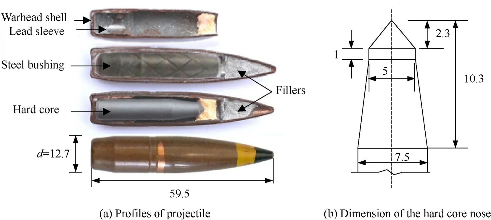
Fig.3.Profiles of projectile structure(units:mm).
2.2.Specimens design and fabrication
2.2.1.Specimens design
Considering the potential engineering application of the grid STCC targets in Fig.1(a),the 9-cell square STCC targets are isolated and designed,as shown in Fig.1(b).Moreover,single-cell square STCC targets shown in Fig.1(c)were also design for the purposes of comparison.The tested targets are listed in Table 1,in which No.1—7 are the 9-cell grid STCC targets and they are marked with WS.The first and second numbers after WS indicate the diameter of the circumscribed circle and the thickness of the steel tube,respectively.The 7 series of WS targets are designed with side lengths of 70—140 mm(the diameter of circumscribed circle of the cell is 99—198 mm)and steel tube's thickness of 2.5—4.5 mm.In addition,the single-cell square STCC target is marked as S135.The tube thickness and the side length of S135 are 3.5 mm and 95 mm(the diameter of circumscribed circle is 135 mm),respectively.All the targets are designed as thick targets.The depth of S135 is 300 mm,and the depth of the WS series is designed as 250 mm,since the DOP in the composite STCC is expected to be smaller owing to the confinement effect of the surrounding cells.

Table 1Dimensions of the specimens and impact conditions.
The steel ratio ρ for WS targets is represented by the steel ratio of the central cell,i.e.,the ratio of the cross-sectional area of the steel tube and the central cell surrounded by the mid-thickness surfaces of steel tubes.
The WS series targets in Table 1 can be divided into 4 groups.The first group,i.e.,No.1—2 series or No.3—5 series,mainly discusses the influence of steel tube thickness.Moreover,No.4 series have the same thickness and side length of steel tube as those of No.8(S135)series;thus,the confinement effect of the surrounding cells can be explored by comparing the two series targets.The second group,i.e.,No.1 and 3 series,No.2,4 and 7 series,or No.5 and 6 series,is mainly focused on the influence of side length of steel tube.The third group,i.e.,No.1,4 and 6 series,mainly discusses the combination of the side length and thickness of steel tube with a similar steel ratio.The fourth group,i.e.,series No.4,is mainly focused on the influence of the impact velocity with three designed impact velocities(about 800 m/s,700 m/s and 600 m/s).Furthermore,the 7-cell hexagonal STCC targets and the SIC targets reported by Song et al.[20]are used for comparison with S135 and WS targets to analyze the anti-penetration performance and confinement effect of grid steel tubes.
2.2.2.Specimens fabrication
Low carbon structural steel was used for the steel tube;and its elastic modulus and yield strength are 199 GPa and 465.8 MPa,respectively.For WS targets,interlocked method was introduced to design and manufacture the grid steel tubes,as shown in Fig.4.Firstly,the inner steel diaphragm was cut with slots width of the thickness of steel plate and length of half of the height of steel plate.Then,the four inner steel diaphragms were interlocked and fixed by spot welding at the bottom of cutting edge.Moreover,two Lshaped steel plates were processed.Finally,the outer L-shaped steel plates and inner steel diaphragms were fixed by fillet weld.
The grid steel tubes were filled with self-compacting concrete(SCC)and the mixture proportion of concrete is listed in Table 2.The mixing and curing processes of the concrete are the same as those in Ref.[20].Cubic concrete specimens with dimensions of 150 mm×150 mm×150 mm were also prepared to determine their compressive strength.The average cubic compressive strength and splitting strength were 73.0 MPa and 6.0 MPa at the day of the penetration tests,respectively,which are the same as the those of the concrete used in Ref.[20].
3.Test results and discussion
3.1.Test results
According to the design conditions in Table 1,totally,8 series with 28 targets were tested,and the results are listed in Table 3.In Table 3,"normal"and"oblique"stands for the initial normal impact posture of 12.7 mm APP according to the recorded results of the high-speed camera.The former and latter mean that the angle between the axis of the projectile and the normal line of the target surface is no less than and larger than 5,respectively[20].The typical"normal"and"oblique"impact posture are shown in Fig.5.
SCC with coarse aggregates may result in performance differences of the lower and upper concrete layers as a result of the action of gravity[20].According to the concrete pouring direction,the initial pouring surface is marked with"bottom"while another surface is marked with"top".Some of the targets in Table 1 were designed with different impacted surface to investigate the influence of non-homogeneity of SCC on anti-penetration performance.
The definition of damage parameters in the impacted cell is shown in Fig.6 and the corresponding measured results are listed in Table 3,where His the maximum height of the exposed wall of steel tube near the impact point;His minimum height of the exposed wall of steel tube on the other side;Hand Hrepresents the depth of crater(DOC)and tunnel,respectively;H is the total DOP,i.e.,the sum of Hand H;Vis the VOC;D is the diameter of tunnel entrance;Δd is defined as the distance from the center of ballistic crater to the center of the impacted cell[15—18,20].Moreover,when a bulge or perforation formed in the wall of steel tube of the impacted cell,it is recorded as“perforation”or“bulge”in Table 3,which is classified as abnormal results of DOP for the current research in this paper.

Table 2Ingredients and mix proportion of concrete(kg/m3).
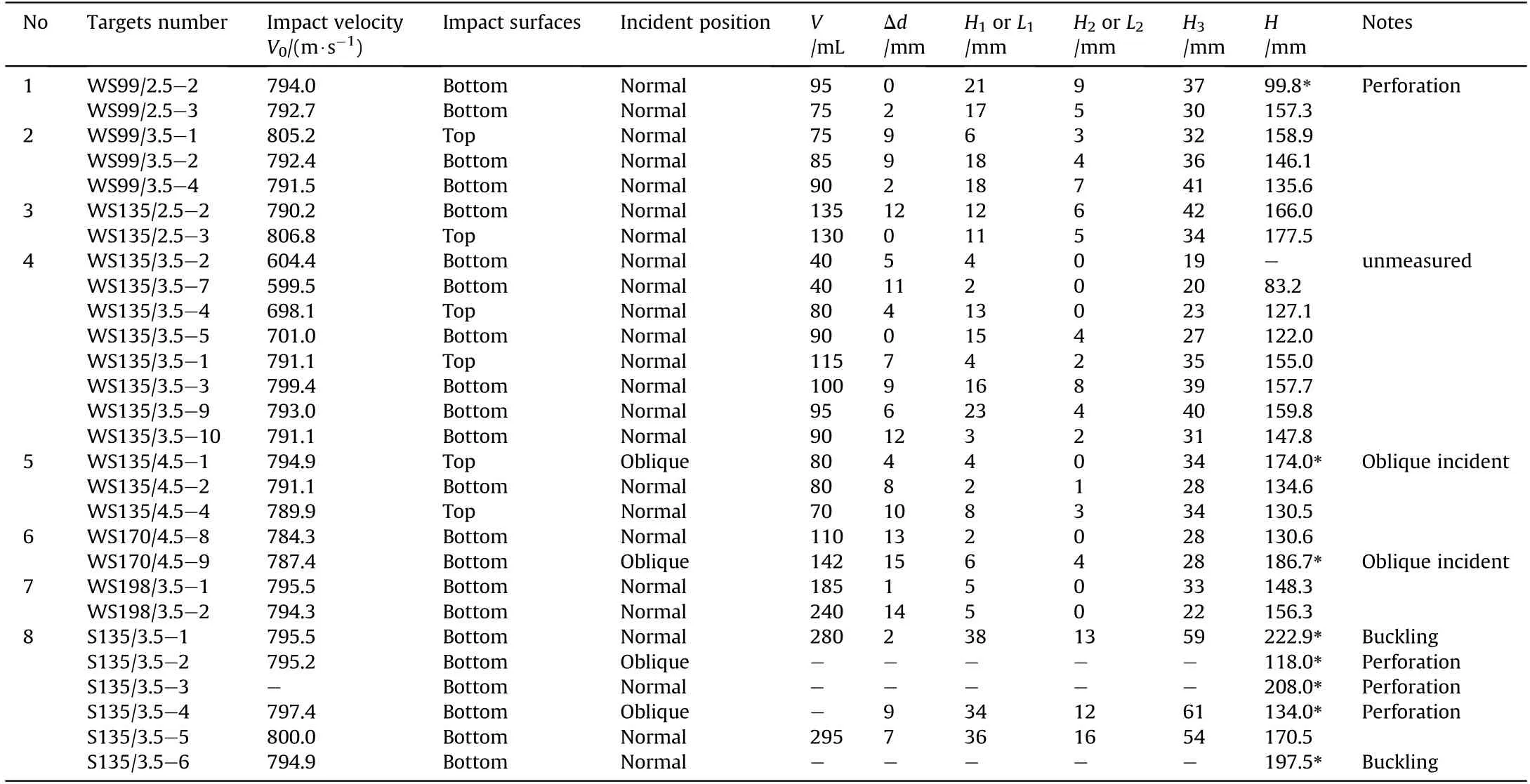
Table 3Damage parameters of target concrete.
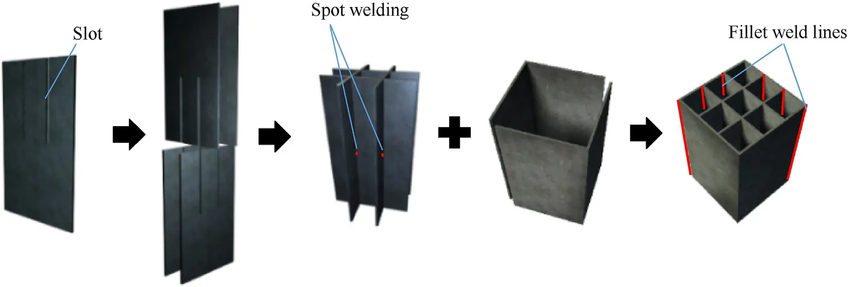
Fig.4.The interlocked method of grid steel tubes.
After cutting the targets along the trajectory,parts of the hard cores of 12.7 mm APPs were collected,as shown in Fig.7.It can be concluded that all the collected cores almost remained intact after a dimension and mass evaluation of the collected cores.
3.2.Damage modes
3.2.1.Single-cell square STCC targets
Damage description of single-cell STCC targets(S135)is shown in Fig.8.It is shown in Fig.8(a)that a funneled crater is formed in the front surface of the concrete and the outer wall of the steel tubes is obviously bent and deformed;the corner of the steel tube is passivated and the cross-section of steel tube shows a round tendency;the concrete of the rear surface shows no obvious damage and can be regarded as a thick target.Similar to the single-cell targets with circular steel tubes reported in Ref.[16],the ballistic trajectory is easily deflected,causing the bulge or perforation of steel tube shown in Fig.8(b)and(c),respectively.There are two main reasons for the deflection of the ballistic trajectory:the first is that the concrete contains coarse aggregate,and the projectile was subjected to the asymmetric action of the uneven ingredients of concrete during the penetration process;the second is the structural influence of the projectile,i.e.,the tungsten core of the projectile is wrapped by a copper sleeve and a copper sheath,as shown in Fig.3(a),and the tungsten core is separated from the outer wrap during the cratering stage,which may cause deflection of the tungsten core with ballistic deflection during the tunneling stage.

Fig.5.The initial incident posture of projectiles with high-velocity camera images.
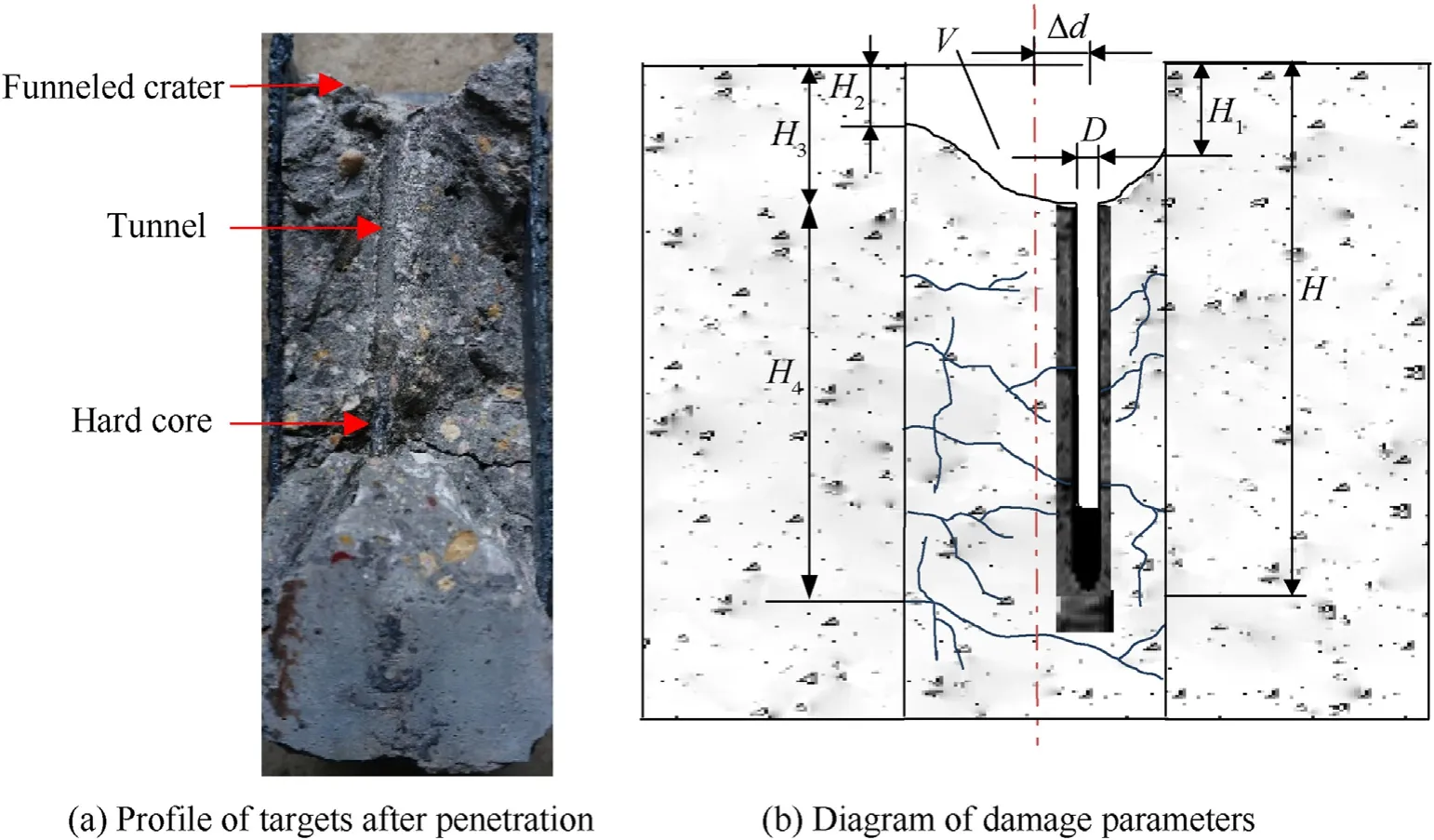
Fig.6.Damage parameters of concrete in the impacted cell.
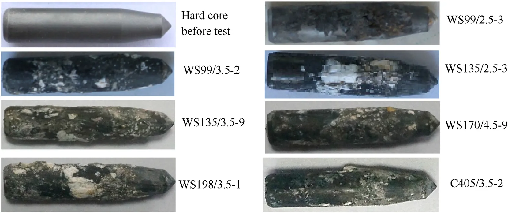
Fig.7.Collected hard cores after penetration tests.
3.2.2.9-cell grid STCC targets
Typical damage of the impacted cell of 9-cell grid STCC targets(the WS series targets)is shown in Fig.9.A funneled crater is formed at the front surface of concrete and limited within the impacted cell.The plastic deformation of the steel tube is not obvious and much smaller than the single-cell square STCC targets,as shown in Fig.9(b).There is no visible damage at rear surface of the impact cell,as shown in Fig.9(c),and the test specimens can be regarded as a thick target.
The surrounding cells of typical test targets(WS198/3.5—1 and WS135/3.5—2)after the steel tube was cut are shown in Fig.10,indicating that the concrete in the surrounding cells is notdamaged.Fig.11 shows the crack distribution of the core concrete of the typical WS series targets.The wide crack of WS135/3.5—10 is depicted by a silver pen,while the wide crack of WS135/2.5—3 is depicted by a pink pen.It can be seen that the main cracks on the side surfaces of the concrete are shown in the impacted cell,which is remarkably influenced by the impact velocity V,the side length and thickness of the steel tubes:the number and width of cracks increase with the increase of V,as shown in Fig.11(a),while theydecrease with increasing the thickness of the steel tube and decreasing side length of the steel tube,as shown in Fig.11(b)and(c).
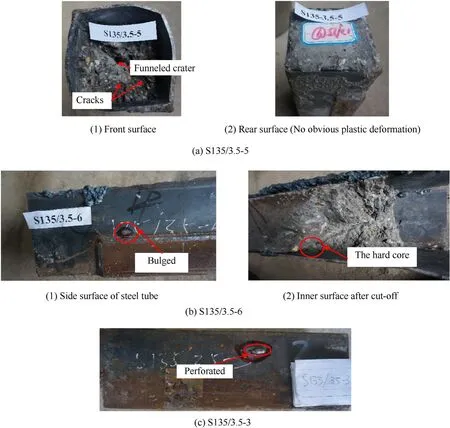
Fig.8.Damage of single-cell square STCC targets(Series S135/3.5).
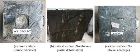
Fig.9.Typical damage modes of 9-cell grid STCC targets with different dimension matching under central incident(WS135/3.5—2).
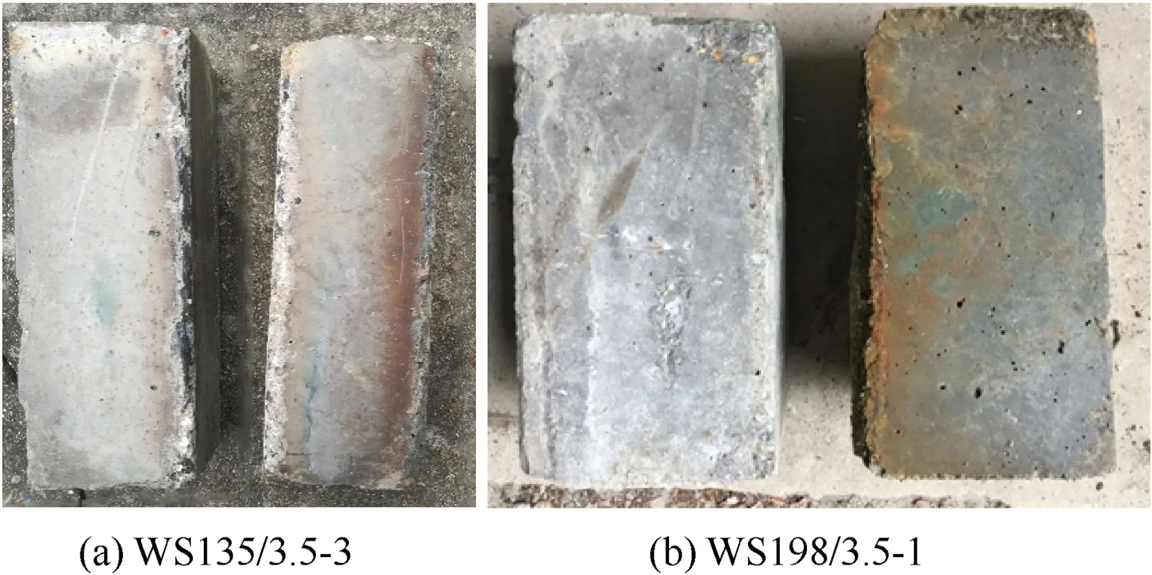
Fig.10.Lateral surface of the surrounding cells.
After the penetration tests,the typical targets were cut along ballistic trajectory in the impacted cell and the corresponding profiles of the ballistic trajectory in combination with the highspeed camera images of the projectile are shown in Fig.12.It is shown from Fig.12 that,similar to the SIC targets[20],S135 targets shown in Fig.8(b)and the cellular STCC targets in Ref.[20],the interaction process between projectile and concrete includes both the cratering and tunneling stages.Diameter of the tunnel is close to the diameter of the tungsten hard core.That is,the steel sleeve and the copper skin of the projectile are separated from the tungsten core in the cratering stage,and only the tungsten hard core penetrates to form the tunnel.In general,the ballistic trajectory of the WS series targets shown in Fig.12(a)are deflected,but most of the deflection is slight and much smaller than that of S135 targets due to the confinement effect of the surrounding cells to the impacted cell in the WS series targets.In addition,few of targets with smaller side length and thickness of steel tubes(WS99/2.5 series targets)or targets with oblique incidence shown in Fig.5(b),have severe deflected ballistic trajectory,as shown in Fig.12(b).
3.3.Damage parameters
The damage parameters,as shown in Fig.6,including the volume,diameter and depth of crater and DOP,are obtained and adapted to indirectly assess the confinement effect and the penetration resistance of grid STCC targets.The measured results are listed in Table 3.
3.3.1.The volume of crater(VOC)
Fig.13 shows a comparative histogram of the VOC for WS series,S135 series and SIC targets(C405 series)reported by Song et al.[20]at the impact velocity of about 800 m/s,where the top and bottom of vertical bars represent the maximum and minimum values,respectively.The black solid squares represent average values.It can be seen from Fig.13 that the VOC for the WS series targets(No.1—7)generally increases with the increase of the side length(outer diameter)of the steel tube or the decrease of the thickness of the steel tube;when the thickness of the steel tube for the targets is 3.5 mm,the VOC for WS198/3.5 is 2.7 times and 3.2 times of that of WS135/3.5 and WS99/3.5,respectively;when the steel tube has the same side length(the circumscribed circle diameter is 135 mm),the VOC for WS135/4.5 is reduced by 23.3%and 37.8%in comparison to that of WS135/3.5 and WS135/2.5,respectively.Furthermore,the VOC for the WS series targets is greatly reduced in comparison to the single-cell square STCC targets(S135 series)and SIC targets(C405 series)owing to the higher confinement of the steel tube and surrounding cells.Additionally,the concrete collapse of the front surface for the WS series targets also can be effectively reduced.
For the WS series targets(No.1—7 targets shown in Table 3),the difference of concrete damage between the frontal impact and the bottom impact is small.This is because the depth of the targets is relatively small,resulting in the insignificant difference of concrete performance between the upper and lower parts.Therefore,the influence of the front and bottom impact of the WS series targets can be ignored.
The impact velocity significantly influences the VOC,and the VOC increases with the increasing impact velocity for WS135/3.5 targets at different impact velocities(No.4 targets in Table 3);when the impact velocity is about 800 m/s,it is 2.5 times and 1.2 times of that with the impact velocity of about 600 m/s and 700 m/s,respectively.
3.3.2.The depth of crater(DOC)
Comparison of DOC for different types of targets with the impact velocity of about 800 m/s is shown in Fig.14.In Fig.14,the top and bottom of the vertical bars represent the maximum and the minimum values,respectively,while the solid black square indicates the average value.The WS170/4.5 and S135 series targets have the same DOC values,hence they have no vertical bars.It is inferred from Fig.14 and Table 3 that:
(1)The DOC for the WS series targets is ranged from 22 mm to 38 mm.The thickness of steel tube has some influence on the DOC.The DOC of the WS135/4.5 series targets is 14.3 % and 36.9 % lower than that of the WS135/3.5 and WS135/2.5 series targets,respectively.
(2)The DOC for the WS series targets is lower than that of the S135 series targets since the impacted cell of the WS series targets is confined by the surrounding cells.Especially,it is reduced by about 37 % for the WS135/3.5 series targets in comparison with that of the S135 series targets.

Fig.11.Damage of concrete in the impacted cells for 9-cell grid STCC targets with different parameters.
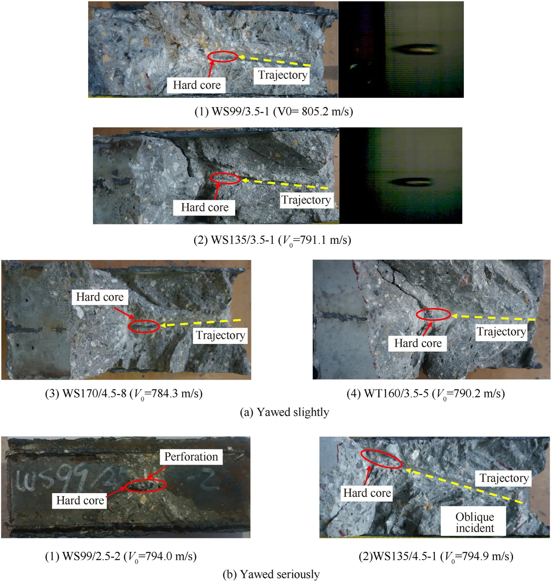
Fig.12.Profile of the ballistic trajectory of projectiles.
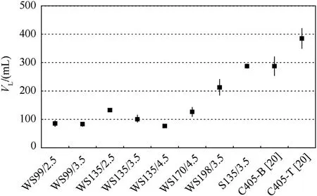
Fig.13.Relationship between VOC and types of targets with the design impact velocity of 800 m/s.
(3)The DOC for all the WS series targets is generally smaller than that of the SIC targets(C405 series)in Ref.[20].The possible reason is that the diameter of the SIC targets is large[20],and the side surface is unconstrained in comparison to the WS series targets.However,the DOC of the S135 series targets is larger than that of the SIC targets since the side length and thickness of steel tube is relatively small and the confinement effect of the steel tube to the concrete is weaker than the self-confinement of concrete of the SIC targets[20].
(4)It can be seen from No.1—7 series targets in Table 3 that the maximum and minimum heights(Hand H)of the WS series targets is within 23 mm and 10 mm,respectively.Most values of Hfor the WS series targets is almost 0,which shows that the confinement effect of the surrounding cells can effectively limiting the concrete collapse.For No.8 series targets in Table 3,the maximum and minimum heights(Hand H)of the S135 series targets are above 34 mm and 12 mm,respectively,which is significantly larger than that ofthe WS series targets.The above comparison shows that the grid STCC targets not only limit the concrete spalling within the impacted cell,but also reduce the volume of concrete spalling.
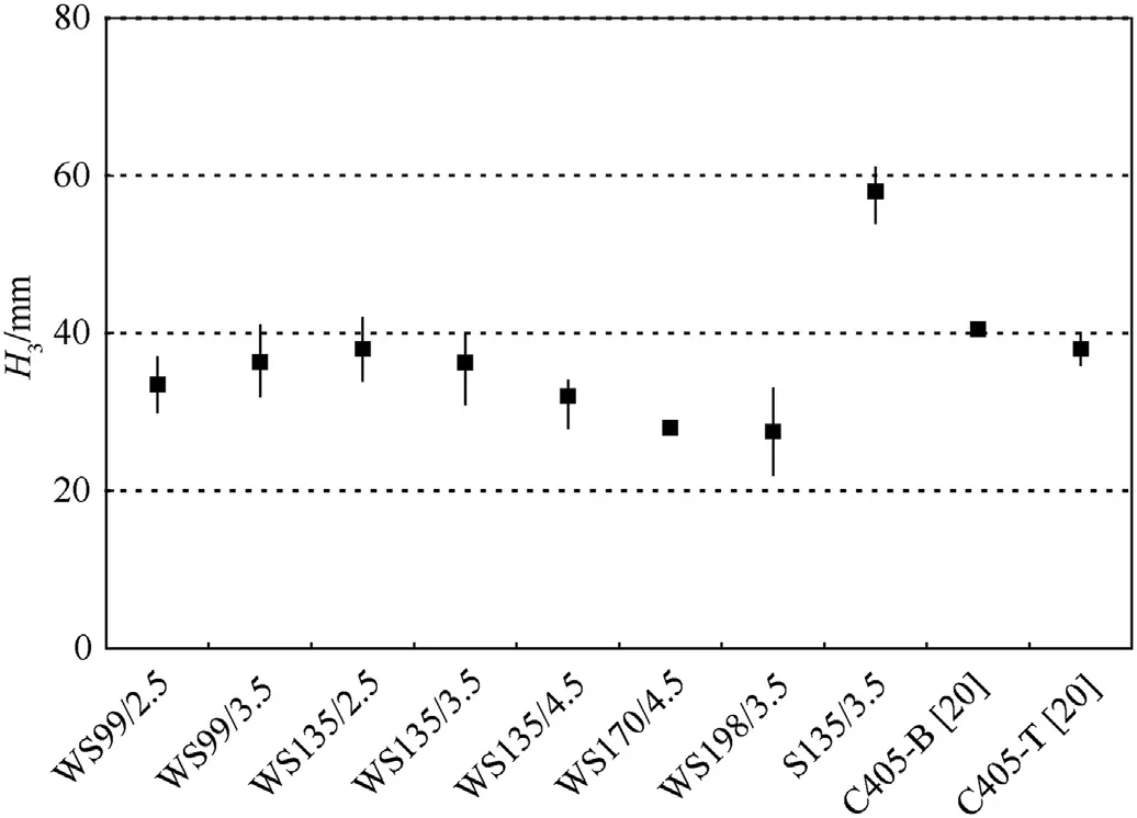
Fig.14.Relationship between DOC and types of targets with the design impact velocity of 800 m/s.
(5)The DOC for WS135/3.5 at different impact velocities in Table 3(No.4 targets)shows that the impact velocity also significantly influences the DOC.The DOC for the targets with the impact velocity of about 600 m/s,700 m/s and 800 m/s,is approximately 1.5,2 and 3 times of the diameter of the hard core,respectively.
3.4.Analysis of DOP
The"abnormal"conditions,such as the oblique incidence,the bulge,perforation and the unmeasured DOP in Tables 3 and i.e.,the DOP results marked with asterisk,are excluded,and the remaining DOP values are regarded as valid results for comparison and analysis in this paper.
3.4.1.Influence of type of targets and dimensions of steel tube

Fig.15.Relationship between average DOP and types of targets with the design impact velocity of 800 m/s.
Histogram of DOP for different types of targets,i.e.,the WS series targets(No.1—7)and S135 series targets(No.8)in Table 3 with the impact velocity of around 800 m/s,is shown in Fig.15,where the abscissa is the targets label,and the ordinate is the DOP;the top and bottom of vertical lines represent the maximum and minimum values of DOP,respectively,and the black solid squares represent the average values;the WS99/2.5,WS170/4.5 and the S135 series targets have only one effective value,therefore there is no vertical line in Fig.15.It is shown from Fig.15 that the S135 series targets have the highest average values of DOP,which is about 7.9%more than that of the frontal impact SIC targets(C405-T series in Ref.[20])and about 10 % more than the WS135/3.5 series targets.Therefore,the DOP of the STCC targets can be less than those of the SIC targets with the rational match between the thickness and side length of steel tubes.
Generally,within the elastic stage,the larger the thickness of steel tube or the smaller the side length of steel tube,the stronger the confinement effect of steel tube to concrete.The DOP decreases with the increasing thickness of steel tube.The average DOP of the WS99/3.5 series targets was reduced by about 7%compared to that of the WS99/2.5 series targets,and the average DOP of the WS135/4.5 series targets was reduced by about 19 % and 14 % over the WS135/2.5 and WS135/3.5 series targets,respectively,i.e.,the thickness of the steel tube significantly influences the antipenetration performance of the targets.The side length of steel tube has a moderate influence on the DOP of WS targets under the conditions of the same tube thickness.The average DOP of the WS198/3.5 and WS135/3.5 series targets is similar,which is 3 %higher than that of the WS99/3.5 series targets with a smaller side length of steel tube.The average DOP of the WS135/2.5 series targets is approximately 4 % greater than that of the WS99/2.5 series targets,that is,the smaller the side length of steel tube,the stronger the confinement effect of steel tube to concrete and the smaller the DOP.However,the average DOP of the WS135/4.5 series targets is approximately 2%greater than that of the WS170/4.5 series targets with a larger side length of steel tube.That is because the relatively large side length of the WS170/4.5 series targets contributes to a stronger self-confinement of concrete as well as a higher confinement effect of steel tube,in comparison with the WS135/4.5 series targets.The results indicate that there is an optimal dimension match between the side length and thickness of steel tube.
3.4.2.Influence of steel ratio
Steel ratio is an important economic index of protective structures.In combination with the DOP and the steel ratio,the comprehensive indexΔH/ρ is used for assessing the antipenetration performance of the STCC targets,considering the DOP and the steel ratio.ΔH is the difference between the DOP of the simulated SIC targets(C405-T in Ref.[20])and the grid STCC targets.The larger theΔH,the stronger the confinement effect of the steel tube.Fig.16 shows the relationship between the comprehensive indexΔH/ρ and the steel ratio ρ of the WS series targets(No.1—7 in Table 3)under 800 m/s.For convenience of comparison,the DOP of the targets is connected to form a fold line according to the increasing ρ,wherein the upper and lower ends of the line segments represent the maximum and minimum values,respectively,and the solid square represents the average value.
It is shown from Fig.16 that theΔH/ρ value of the WS170/4.5 series targets(with a steel ratio of 7.50 %)is the largest,and the corresponding DOP is the smallest.Its steel ratio is only increased by 0.13 % compared with the WS135/3.5 series targets(with steel ratio of 7.37 %),but theΔH/ρ is increased by 8.3 times.The steel ratio of the WS135/4.5 series target is 0.52 % lower than that of WS99/3.5,but the correspondingΔH/ρ is increased by 140 %.However,part ofΔH/ρ values of the WS135/2.5 series target(steel ratio of 5.26 %)is negative,indicating that the design dimension match between side length and thickness of the steel tube is not reasonable,which results in a reduced anti-penetrationperformance.
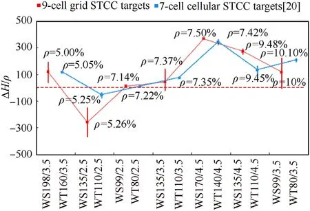
Fig.16.Relationship between DOP and dimension matching of steel tubes with the design impact velocity of 800 m/s.
Generally,for the DOP of the grid STCC targets penetrated by 12.7 mm APP,the value ofΔH/ρ is small,even negative when ρ is less than 7.14%.Therefore,this range of ρ is advised to be avoided.When 7.14%≤ρ≤9.45%,the value ofΔH/ρ increases first and then decreases with the increasing ρ.An optimal dimension match is achieved when ρ approximately equals to 7.5%.Furthermore,when ρ is more than 9.45 %,the increment ofΔH/ρ is small with the increasing ρ,which is also not suitable to be used.
TheΔH/ρ of the cellular STCC targets conducted by Song et al.[20]is also shown in Fig.16 in order to analyze the effects of crosssectional profile on the resistance of composite STCC.It can be seen from Fig.16 that the variation ofΔH/ρ with the increasing ρ is similar for the two types of targets,and the ρ of the optimal dimension match is also similar.In addition,when the ρ of the two types of targets is close,the DOP is also close,that is,the confinement effect of the two types of targets is similar.Therefore,considering the simpler manufacturing process and the excellent in-plane expandability of square steel tubes,grid STCC targets are preferred in engineering practice.
4.DOP model of grid STCC targets based on dynamic FSCE theory
4.1.Basic assumptions and equivalent confinement stiffness
4.1.1.Basic assumptions
According to the results of the penetration tests,as shown in Figs.6 and 12,the total depth of penetration(H)for STCC targets is the sum of the depth at cratering stage(H)and tunneling penetration stage(H),i.e.

where H=kd,d is the diameter of the projectile,and k is an empirical constant.According to the test results,for the grid STCC targets(WS series),k can be taken as 1.5,2 and 3 with impact velocities about 600 m/s,700 m/s and 800 m/s,respectively;for the single-cell square STCC(S135 series)and the SIC targets(C405 series in Ref.[20]),k can be taken as 4.
The following basic assumptions are adopted to calculate the DOP at the tunneling penetration stage(H):
(1)Influence of eccentricity and deflected ballistic trajectory are ignored,i.e.,it is assumed that the impacted cell is normally penetrated by the projectile.Furthermore,velocity loss of the projectile is also neglected during the cratering stage for that the steel sleeve and the copper skin of the projectile are separated from the rigid hard core in this stage.Therefore,the initial velocity of the hard core in tunneling stage is equal to the impact velocity of the projectile(V)[15—18].
(2)The steel tube of the impacted cell and the surrounding cells including the steel tube and concrete are in elastic state,thereafter,the core concrete in the impacted cell is confined by both the steel tube and the surrounding cells,as shown in Fig.17(a),where Kis confinement stiffness of the concrete of the surrounding cells.The radial stress at cavity wall during the tunneling stage is calculated on the basis of FSCE model[38],which is based on elastically confined concrete targets,as shown in Fig.17(c),where rand˙rare the cavity radius and cavity expansion velocity,respectively,and ris the equivalent radius of impacted core concrete.K is the radial elastic confinement stiffness,including the confinement of the surrounding cells and steel tube of the impacted cell.
(3)In order to obtain the confinement stiffness K,the polygonal(square and hexagonal)steel tube is approximately equivalent to a circular steel tube(i.e.,a inscribed circle of the polygon)with the same thickness of steel tube and steel ratio,as shown in Fig.17(b).
4.1.2.Equivalent confinement stiffness
The confinement stiffness K is calculated on the basis of the mechanical model of a cylindrical shell with an infinite length in Winkler elastic medium under local uniformly internal pressure.The range of the internal pressure is equal to length of projectile head(l),as shown in Fig.18(a).The central axis of the cylindrical shell is taken as x-axis,and the midpoint of the local internal pressure length is taken as the origin of coordinates.Therefore,the radial displacement wat the origin of coordinates reaches the maximum under the action of the local load q.The radial displacement wis obtained according to symmetry and superposition principle,as shown in Eq.(2).


For the problem of axisymmetric deformation of a cylindrical shell with infinite length under inner pressure,the governing differential equation is shown in Eq.(3)[39]:

where E,υ,δ and rare elastic modulus,Poisson's ratio,thickness and radius of mid-height surface of steel tube,respectively.
The constrained force of surrounding cells on impacted cell can be simplified as Kw according to assumption(2).Therefore,differential equation of cylindrical shell is transformed into Eq.(4):

Eq.(4)can be transformed into a standard form:


where C(i=1—4)is an integral constant.
The boundary conditions are shown in Eq.(7)for the mechanical model of a cylindrical shell with an infinite length in Winkler elastic medium.

Therefore,the four integral constants in Eq.(6)can be solved:

Substituting Eq.(8)into Eq.(6)can get
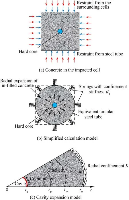
Fig.17.Simplified models of penetration resistance of concrete in the impacted cell.

Fig.18.Cylindrical shell under loading.

Substituting Eq.(9)into Eq.(2)gets

Letting w=1 and K=qgets

Letting l→∞gets η→1,and then K=Kin Eq.(11).Kis the stiffness coefficient of the cylindrical shell in the elastic medium subjected to uniform internal pressure,and Kis shown in Eq.(12):

where Eis the elastic modulus of concrete;ris the inner radius of the equivalent circular steel tube,i.e.,half of the inner side length of the square steel tube;υis the Poisson's ratio of concrete.The corresponding derivation process is shown in Appendix A.
4.2.Radial stress at the cavity wall and penetration resistance
4.2.1.Low confinement(Kr<(Kr))
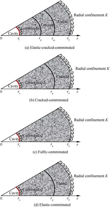
The radial stress at cavity wall of the grid STCC targets is calculated with dynamic FSCE according to the assumption(2).The typical response mode of the finite cavity-expansion process is divided into“elastic-cracked-comminuted”(ECC),“crackedcomminuted”(CC)and“fully comminuted”(C)response phases for low radial confinement(Kr<(Kr))and low cavity expansion velocity(˙r<˙r)[32],i.e.,"ECC-CC-C"response mode,as shown in Fig.19(a)—(c).rand rare elastic-cracked interface radius and cracked-comminuted interface radius,respectively.
Defining rand ras critical cavity radii,i.e.,ris the interface between the first"ECC"and the second"CC"response phases and ris the interface between the second"CC"and the third"C"response phases.It is the first"ECC"response phase when r
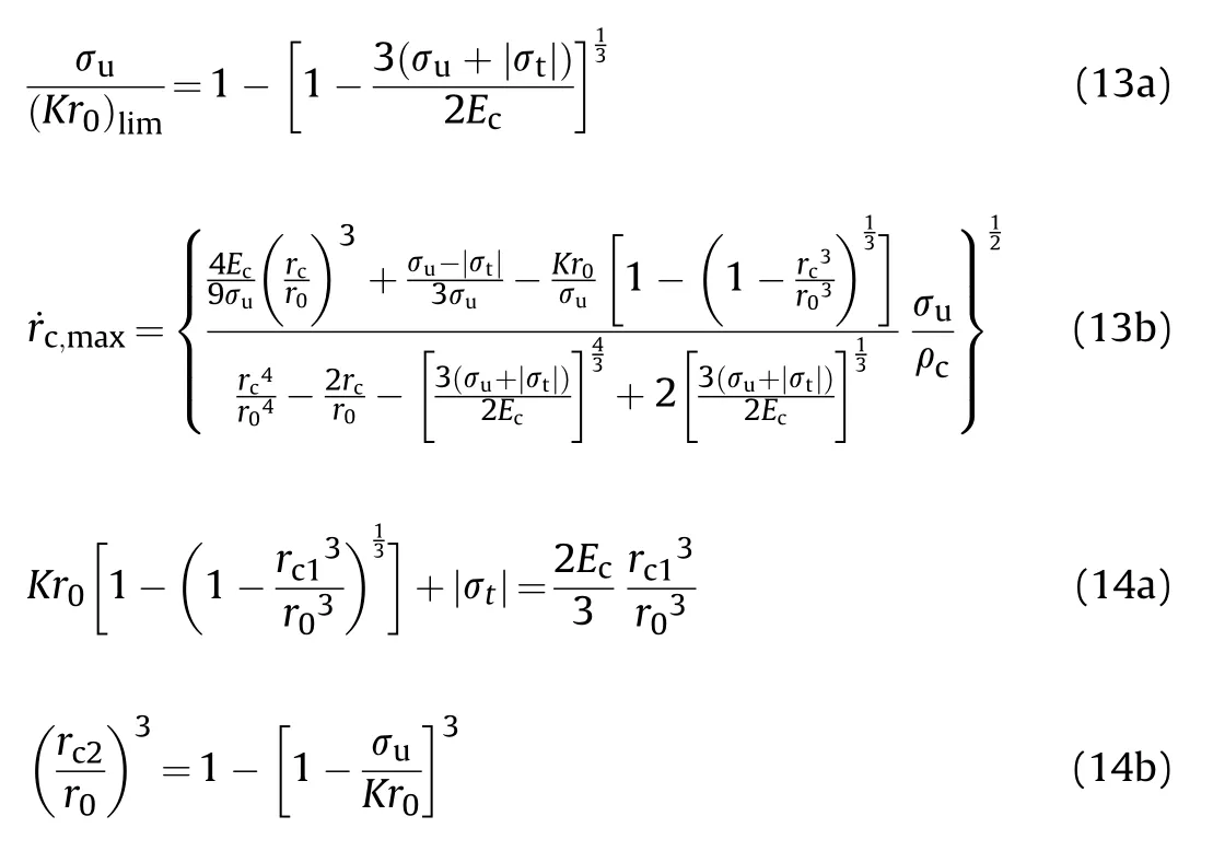
where σand σare the uniaxial tensile strength and the unconfined compressive strength of concrete,respectively.
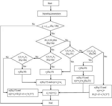
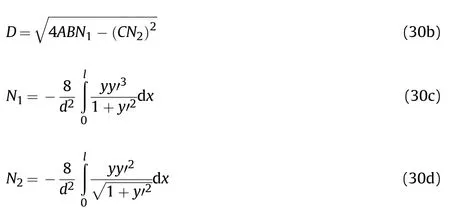
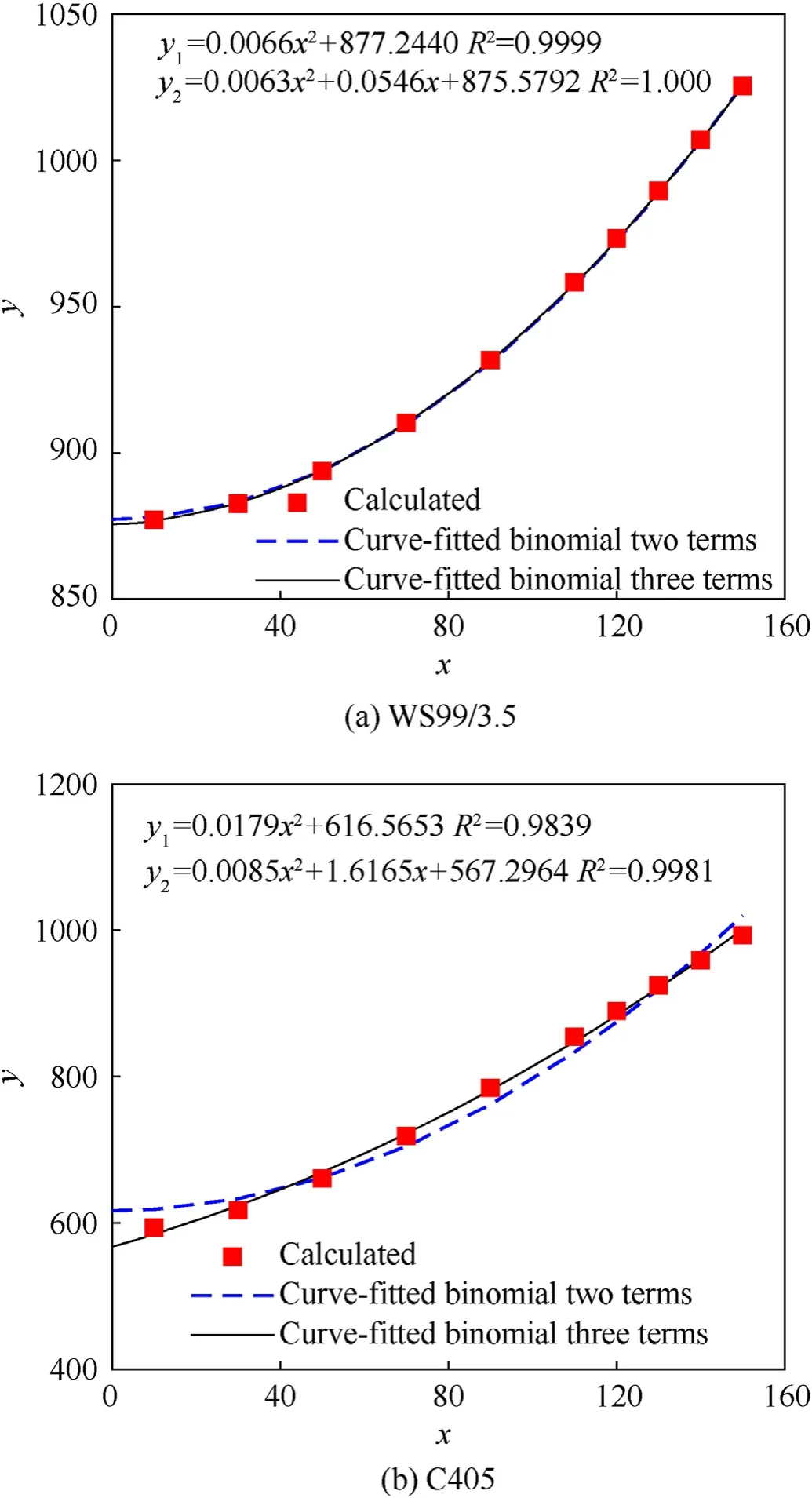
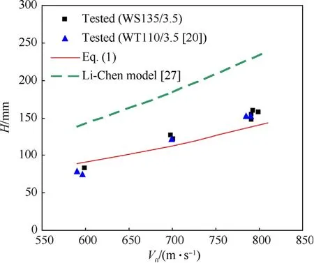
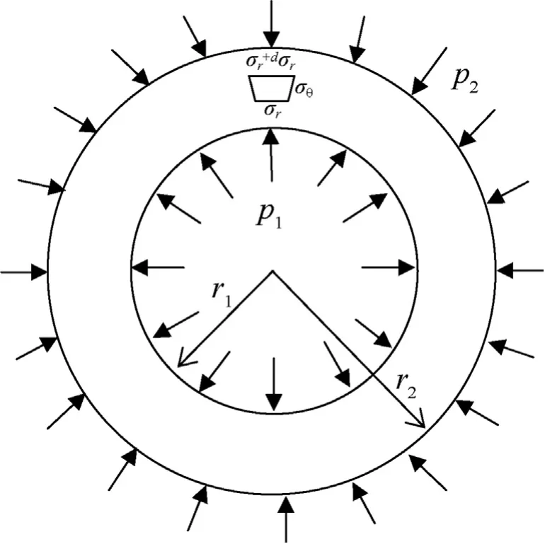
In the first"ECC"response phase(r Fig.19.Response phases of concrete in the STCC targets. where ρis density of concrete. In the comminuted region,it is assumed that the Hoek-Brown criterion can be used to describe the mechanical performance of concrete.The radial stress and hoop stress meet the equation of Hoek-Brown criterion: where σand σare radial and hoop stresses,respectively,and m is an empirical constant in the Hoek-Brown criterion,related to the strength,mixture and confinement of concrete. The radial stress of the cavity wall can be obtained by solving Eq.(17)with the boundary condition of σ=σ(r=r)[38]: where n=m/4+1. In the second"CC"response phase(r≤r≤rand r≡r),the equation for solving the interface radius ris shown in Eq.(18)[38]: The radial stress at cavity wall in this response phase is the same as the first"ECC"response phase. In the third"C"response phase(r>rand r≡r),the method for solving radial stress at cavity wall is similar to the first"ECC"response phase,but the boundary condition of Eq.(17)is σ(r=r)=K[1-(1-r/r)]. 4.2.2.High confinement(Kr0≥(Kr0)) For the grid STCC targets,the radial confinement may be larger than the limited value(Kr≥(Kr))due to the strong confinement of surrounding cells.The radial confinement results in the increase of the radial and hoop compression stresses in the elastic region[38],which may restrain the development of the cracked region if the radial confinement is large enough.The phenomenon that cracked region vanishes before elastic region appears for high confinement(Kr≥(Kr)).Therefore,the response mode in the confined concrete target under a high confinement includes three response phases,i.e.,"elastic-cracked-comminuted"(ECC),"elasticcomminuted"(EC)and"fully comminuted"(C),i.e.,"ECC-EC-C"response mode,as shown in Figs.19(a),(d)and(c).Defining rand ras critical cavity radii for"ECC-EC-C"response mode,i.e.,it is the first"ECC"response phase when r In the first"ECC"response phase(r In the"elastic-comminuted"phase(r≤r≤r),the mechanical properties of the concrete can be described with the Hook's law in the elastic region,and the Hoek—Brown criterion in the comminuted region.The hoop stress at the elastic-comminuted interface is shown in Eqs.(20a)and(20b),respectively[38]: Combing Eq.(20a)and(20b)can get the radial stress at the elastic-comminuted interface according to the condition of continuous circumferential stress: Eq.(21)can be used as the boundary condition to solve the differential Eq.(17). The radial stress at elastic-comminuted interface in elastic region can also be expressed as Eq.(22)[38]: Therefore,the critical radius rcan be obtained according to the condition of continuous radial stress at elastic-comminuted interface by the combination of Eqs.(21)and(22). The procedure to get radial stress at cavity wall in the second"EC"response phase is also similar to the first"ECC"response phase,but the boundary condition is Eq.(21). The second"EC"response phase ends and enters the third"C"response phase when the comminuted zone extends to the outer boundary of the concrete.Letting r=rin Eq.(21)yields the critical cavity radius r: In the third"C"response phase(r>rand r≡r),the solution of radial stress at the cavity wall is the same with that under the low confinement condition. As analytical solution of stress for the two response modes of the STCC targets with dynamic FSCE model are complex,numerical solutions of the radial stress in the response phases and the corresponding zones is solved by Runge-Kutta method and a calculation flowchart is shown in Fig.20. It should be pointed out that similar as the dynamic FSCE model for the single-cell STCC targets[38],compressibility,shear dilatancy,strain-rate,strain-hardening and strain-softening of concrete are not included,which is regard as reasonable at low and medium penetration velocity[29,30].Moreover,it is assumed that the circumferential tensile stress in elastic region reaches the tensile strength of concrete at elastic-cracked interface and concrete in cracked region is regarded as linear elastic with no circumferential stress,however,details of the concrete ingredients and microstructures would affect the crack onset of concrete under static and dynamic conditions[40—42]and hence may influence the confined concrete stress in the impacted cell of the STCC targets.Additionally,the confined concrete strength is also affected by the stresspath dependence of confinement under the static loading,especially for high strength concrete,there is a longer lag between the development of axial strain and that of confining strain and stress when compared with normal-strength concrete[12—14].The superposition of the above factors may cause new errors,which may require further research. 4.3.1.DOP model In tunneling stage,it is generally assumed that the normal penetration resistance of the projectile head is equal to the radial stress at the cavity wall[22],i.e.σ=σ.For the dynamic FSCE model,the relationship between the radial stress at cavity wall and the cavity-expansion velocity can be approximately described with quadratic equations for SIC targets[22,34]: where A,B and C are static resistance,flow resistance and viscous damp coefficient,respectively.σ=σis the normal penetration resistance of the projectile,which is obtained with the solution of the dynamic FSCE model. In order to facilitate the calculation of the drag coefficients A,B and C,letting Eq.(25)is converted into The radial stress at cavity wall can be obtained with the numerical solution of Eq.(16)if the cavity-expansion velocity is given.Therefore,a series of radial stresses at the cavity wall and the related cavity-expansion velocities can be plotted in Cartesian coordinate system,where cavity-expansion velocities act as the independent variable and radial stresses at cavity wall act as the dependent variable.Then the plotted dots in Cartesian coordinate are fitted with the quadratic equation shown in Eq.(27)according to the principle of least squares and maximum fitted coefficient.The penetration resistance coefficients A,B,and C can be obtained by substituting the fitted coefficients b,c,and h in Eq.(27)into the Eq.(26).Fig.21 shows the example to list calculated dots of numerical solution results and obtain the fitted coefficients b,c,and h for the WS99/3.5 and C405 series targets,where Ris the fitting correlation coefficient.The relevant parameter of obtaining the fitted coefficients for the STCC targets are listed in Table 4.The critical cavity-expansion velocity(˙r)is 171.8 m/s and the critical confinement stiffness(Kr/σ)is 800.0.Therefore,the cavityexpansion velocities of the presented examples range from 10 m/s to 150 m/s.In addition,the fitted results of binomial with two terms[23](i.e.,C=0)are also shown in Fig.21. Table 4The relevant parameter of the STCC targets for obtaining the fitted coefficients. It can be seen from Fig.21 that the curve-fitted binomials with two and three terms are in good agreement with the calculated results for the WS99/3.5 series targets because of the larger cavity radius and confinement stiffness,as shown in Fig.21(a).The correlation coefficients are 1.0000 and 0.9999,respectively.However,the curve-fitted binomial with three terms gets better agreement with the calculated results than that with two terms for the C405 series targets because of the smaller cavity radius and confinement stiffness,as shown in Fig.21(b).The corresponding correlationcoefficients are,0.9981 and 0.9839,respectively,which is less than that of the WS99/3.5 series targets.In addition,the intercept(the static resistance)is greater than that when the cavity expansion velocity is 10 m/s with two terms in Eq.(25)used.The equivalent static resistance may overestimate the curve-fitted binomial with two terms.Therefore,the curve-fitted binomial with three terms(Eq.(25))is taken to describe the relationship between the radial stress at the cavity wall and the cavity-expansion velocity. Fig.20.Calculation flowchart of pressure at cavity wall for the STCC targets. In tunneling stage,it is assumed that the penetration is the movement of the projectile whose velocity gradually reduced to zero under the effect of penetration resistance,which refers to the DOP model proposed by Forrestal et al.[22]for the SIC targets.The motion equation of projectile is shown as Eq.(28): where M is mass of projectile and F is penetration resistance. The penetration resistance is a resultant force of normal pressure at the head of the hard core in the axial direction without the friction effect.It is integrated along the head of the hard core in length. where Ω is the area of the head of the hard core;θ is the angle between normal and axial directions of the projectile;dis the diameter of the hard core,and Nand Nare the shape factors of the head of the hard core. Combination of Eq.(28)and Eq.(29)can give the DOP of the tunneling stage(H): where M is the mass of the hard core;y=y(x)and l are the shape function and length of the head of the hard core,respectively. 4.3.2.Validation of the DOP model and discussion In order to validate the applicability of the DOP model developed above,penetration resistance coefficients for the STCC targets in Table 3 are fitted following the process in Section 4.3.1 and listed in Table 5,where the impact velocity and DOP are the average values of the valid data for the same specification of STCC targets.The calculated parameters,being the same with penetration tests and the calculation method in Section 4.3.1,are as follows:unconfined compressive strength of concrete σ=0.8σ=58.4 MPa[43],uniaxial tensile strength|σ|=6.0 MPa,Poisson's ratio υ=0.2,elastic modulus of concrete E=3375σ=25791.7 MPa[44];elastic modulus of steel tube E=199 GPa,Poisson's ratio of steel tube υ=0.3;projectile diameter d=12.7 mm,diameter of the hard core d=7.5 mm,mass of the hard core M=19.8 g,shape coefficient of the hard core N=0.26,N=0.40,head length of the hard core l=10.3 mm,m=8.Critical confinement stiffness(Kr/σ)=800.0,therefore,WS99/2.5,WS135/2.5,S135/3.5 and C405 series are low-confinement targets,while the WS99/3.5,WS135/3.5,WS135/4.5,WS170/4.5 and WS198/3.5 series are highconfinement targets.The response modes and corresponding response phases for all tested targets are listed in Table 6,which shows that the WS99/3.5 and WS135/4.5 series targets are in the“elastic-comminuted”(EC)response phase,while other targets are in“elastic-cracked-comminuted”(ECC)response phase.In addition,the DOPs obtained with the developed model for the grid STCC targets(WS series)and single-cell square STCC targets(S series)are also listed in Table 6.It is shown that the calculated results are in good agreement with the experimental results,with the maximum relative error less than 12 %.It demonstrates that the developed model can be used to predict the DOP of the grid STCC targets. Table 5Penetration resistance coefficients for the STCC targets. Table 6Response phases for the tested STCC targets. The comparison between the developed model and the test results of WS135/3.5 series targets with the three impact velocities are shown in Fig.22.Furthermore,the experimental results of cellular STCC targets conducted by Song et al.[20]are also listed in Fig.22 to further validate the applicability of the proposed model.Additionally,the Li—Chen model[27],which has been extensively utilized in current studies dealing with concrete penetration problems,is also added in Fig.22 for comparison purpose.It can be seen from Fig.22 that the proposed model agrees well with the tested DOP of the grid and cellular STCC targets with the relative errors ranging from-9% to 8 %.The DOPs obtained with the Li—Chen model[27]are more than 50 % higher than the experimental data.This is because the Li—Chen model fail to consider the confinement of the steel tube and surrounding cells on the impacted concrete[20],which underestimates the penetration resistance of the targets.It indicates that the Li—Chen model[27]cannot be used directly to predict DOPs of the grid and cellular STCC targets and the anti-penetration performance of the grid and cellular STCC targets is significantly better than that of the SIC targets.Generally,the proposed model shows more accurate prediction results of DOP for the grid and cellular STCC targets penetrated by rigid projectiles. Fig.21.Curve-fitting of the penetration resistance coefficients. Fig.22.Comparisons between the DOP prediction models and the tested results. Penetration tests of grid STCC targets impacted by 12.7 mm APP were conducted,and the results are compared with those of singlecell STCC,cellular STCC and SIC targets[20].The models to predict the penetration resistance and DOP of the grid STCC targets were established on the basis of dynamic FSCE models with a higher radial confinement.The following conclusions can be summarized: (1)For the grid STCC targets,the concrete damage is limited within the impacted cell and the surrounding cells are not damaged.The cratering and tunneling stages are included in the penetration process.The damage region of concrete in the grid STCC targets is significantly reduced,compared with the single-cell square STCC and SIC targets.The VOC for the grid STCC targets is significantly smaller than the single-cell square STCC targets and is only 20%—70%of the SIC targets. (2)For the grid STCC targets,the impact velocity of the projectile and the thickness of the steel tube significantly influence the DOP,while the side length of the steel tube has moderate influence on the DOP.Generally,the anti-penetration performance of the grid STCC targets is improved with the increase of the steel ratio,but the grid STCC targets have an optimal match of side length and thickness of steel tube.For the tests in this paper,WS170/4.5 series targets(steel ratio is about 7.5 %)is an optimal dimension match,and the corresponding DOP is reduced by about 17 % compared to that of the SIC targets.The DOP of the single-cell square STCC targets(the S135 targets)is the largest,which is about 10 % higher than that of the grid STCC targets(the WS135/3.5 series targets). (3)Since the impacted central cells of the 9-cell grid and 7-cell hexagonal STCC targets are confined by the surrounding cells,the confinement effects of the two kinds of STCC targets are similar.When the steel ratio is similar,the penetration resistance and DOP of the two types of targets are close.Considering the simpler manufacturing process and the excellent in-plane expandability of square steel tubes,grid STCC targets are preferred in engineering practice. (4)The dynamic FSCE theory is extended to predict the DOP of the grid and cellular STCC concrete targets with high confinement(Kr≥(Kr))considering the additional confinement of the surrounding cells to the impacted central cell.The comparisons between the predicted and test results show that the proposed mode agrees well with theexperimental results with a higher accuracy,i.e.,the proposed mode is more applicable to the grid and cellular STCC targets. The authors declare that they have no known competing financial interests or personal relationships that could have appeared to influence the work reported in this paper. The research reported in the paper is part of the projects supported by the Natural Science Foundation of Hunan Province,China(No.2018JJ2470 and 2021JJ30776).The financial support is highly appreciated. Appendix A.Solution to confinement stiffness of the surrounding cells concrete K The infinitely long cylinder with uniform pressure inside and outside is considered,as shown in Fig.A1.The inner and outer radii of the cylinder are rand r,respectively;and the internal and external pressures are pand p,respectively,which can be treated as a plane strain problem.The micro-element with thickness of the cylinder of dr,length of 1 and width of 1 is shown in Fig.A1with the polar coordinate system.It is known from the elastic mechanics that the equilibrium equation of the micro-element satisfy Eq.(A1). Fig.A1.Schematic diagram of an infinitely long cylinder with uniform pressure inside and outside. In polar coordinate system,there is a geometric relationship to the axisymmetric plane strain problem. Combining Eq.(A1)and(A2)with Hook's law can get Eq.(A3). Integral of Eq.(3)gets the displacement u. Where C(i=1 and 2)is the integral constant. The boundary conditions in Fig.20 are shown in Eq.(A5). Combining Eq.(A1)—(A5)can solve the two integration constants. Substituting Eq.(A6)into Eq.(A3)get the radial displacement u. when p=0 and r→∞,the radial displacement u in Eq.(A7)is simplified as Eq.(A8). Let r=r,u=1 can solve pfrom Eq.(A8). Taking E=E,υ=υ,r=r+δ,the confinement stiffness of the surrounding cells concrete Kis obtained,as shown in Eq.(A10).


4.3.DOP model and validation






5.Conclusions



杂志排行
Defence Technology的其它文章
- 3D laser scanning strategy based on cascaded deep neural network
- Damage analysis of POZD coated square reinforced concrete slab under contact blast
- Autonomous maneuver decision-making for a UCAV in short-range aerial combat based on an MS-DDQN algorithm
- The properties of Sn—Zn—Al—La fusible alloy for mitigation devices of solid propellant rocket motors
- The surface activation of boron to improve ignition and combustion characteristic
- Numerical investigation on free air blast loads generated from centerinitiated cylindrical charges with varied aspect ratio in arbitrary orientation
