Reaction characteristic of PTFE/Al/Cu/Pb composites and application in shaped charge liner
2022-09-22HuanGuoGuoYuanfengZhengSuoHeQingBoYuChaoGeHaifuWang
Huan-Guo Guo,Yuan-feng Zheng,Suo He,Qing-Bo Yu,Chao Ge,Hai-fu Wang
Beijing Institute of Technology Institution,China
Keywords:Reactive materials Shaped charge Reactive liner Jet formation Penetration behavior
ABSTRACT In this paper,the reaction characteristic and its application in shaped charge warhead of a novel reactive material,which introduced copper(Cu)and plumbum(Pb)into traditional polytetrafluoroethylene/aluminum(PTFE/Al),are studied.The thermal analysis and chemical reaction behavior of the PTFE/Al/Cu/Pb mixture are investigated by Differential Scanning Calorimetry(DSC),Thermo-gravimetry(TG),and Xray Diffraction(XRD)techniques.Then,the shaped charge liners with PTFE/Al/Cu/Pb reactive materials are fabricated,and the X-ray experiments show that they could form reactive jets with excellent performance under the detonation effects of the shaped charge.Based on that,the penetration experiments of shaped charge with PTFE/Al/Cu/Pb reactive liner against steel plates are carried out,and the results demonstrate that the PTFE/Al/Cu/Pb reactive jets could produce a deeper penetration depth compared to the traditional PTFE/Al reactive jets.Meanwhile,the PTFE/Al/Cu/Pb reactive jets also show significant inner-blast effects,leading to dramatically cracking or fragmentation behavior of the penetrated steel plates.This new PTFE/Al/Cu/Pb reactive liner shaped charge presents enhanced penetration behavior for steel targets that incorporates the penetration capability of a high-density and ductility jet,and the chemical energy release of PTFE-matrix reactive materials.
1.Introduction
Reactive materials are a class of solid energetic materials that are formulated to release their chemical energy under highly dynamic loads or high strain rates[1,2].In general,they are formed by introducing active metal powders into polymer binder,typically such as PTFE/Al,PTFE/Ti,and PTFE/Cu,and then consolidated by a pressing/sintering process[3,4].By now,many researches on formulations and fabrications[5],mechanical properties[6,7],energy release[8,9],and reaction mechanisms[10,11]have been conducted,which greatly promoted the development of reactive materials.Owing to the proper material strength and high energetic characteristics,the reactive materials present a novel defeat mechanism that incorporates the kinetic energy penetration and chemical energy release[12].As such,reactive materials are considered as potential choice for traditional warheads.For example,reactive materials are used as fragments in anti-aircraft fragmentation warheads,by projecting reactive fragments inside the target to cause catastrophic structural damage[13,14].It can also be used in penetrating warheads,by incorporating reactive materials as replacement for part of the inert penetrator[15].
Meanwhile,there is a growing interest in the development of reactive materials for shaped charge liners,which can produce an energetic jet that releases its chemical energy inside of the target for enhancement of lethality against various potential targets,such as airfield runway,concrete bridge pier,reinforced concrete wall,etc.[16,17].Studies on armored targets showed that,compared with traditional metal liner shaped charge,a relative larger hole diameter accompanying with fragmentation effects of penetrating steel plates was produced by PTFE/Al reactive liner shaped charge[18,19].However,further experiments of PTFE/Al reactive jets against steel plates demonstrated that the penetration depths were only 0.79,0.73,and 0.76 CD(charge diameter)at different standoffs of 0.5,1.0,and 1.5 CD,respectively[20].This was mainly because the density of conventional PTFE/Al reactive liner is not enough to ensure that the corresponding jet produce a deep penetration,which significantly limits the application of this class of PTFEmatrix reactive materials.
Owing to high density and excellent ductility of copper material,it has been mixed with the PTFE powders to fabricate a PTFE/Cu reactive liner.Compared with the low-density PTFE/Al jet,the experimental results have verified that the penetration performance of PTFE/Cu jet has improved significantly[21].Moreover,the addition of Cu,Pb,and Ni powders affecting the friction and wear properties of PTFE-based composites was analyzed[22].In addition to this class of PTFE-based reactive liners,those only composed by metal powders have also been widely studied in recent years.Voitenko presented the experimental data on the shaped charge with Cu-Al and W-Al pressed powder liners penetrating steel targets,and the results showed that the penetration depth increased with decreasing of the Al content[23].Claridge studied the deformation behavior of Ni-Al reactive powder systems under high strain rate and impact loadings,and further analyzed the jet formation behavior of Ni-Al reactive liner shaped charge using flash Xrays[24].The experiments of Ni-Al and Cu-Ni-Al reactive jet against steel targets were performed,and the results indicated that the addition of Cu could increase the average penetration depth by approximately 42% compared with the Ni-Al reactive jet[25].Actually,the metal powders-only composed reactive materials are more likely to react with a wealth of reaction heat released,but they can hardly generate gaseous products,causing these jets failing to produce blasting effect.
Based on the studies above,reactive liner materials with higher density and excellent ductility are necessary to form a consecutive reactive jet.Meanwhile,reactive jets with the potential of releasing gaseous products are also strongly demanded.As such,a novel formulation system of PTFE/Al/Cu/Pb for reactive liner is proposed and studied in this paper.Firstly,the formulation system,reaction characteristics,preparation process,and microstructure of this new kind of reactive liner were investigated.Secondly,the formation behavior of PTFE/Al/Cu/Pb reactive jet was demonstrated by X-ray scaled-down experiments.Thirdly,the penetration performance of PTFE/Al/Cu/Pb reactive jet was verified and discussed.
2.Reactive liner samples
2.1.Formulation system
The formulation system of high-density reactive materials in this paper includes three kinds of metal powders,such as Al,Cu,and Pb powders.Actually,the Cu powder is a crucial component to improve the total density,and its excellent ductility during the jet formation process is also very important.The Pb powder is also considered due to its excellent performance of high-density and vaporization behavior.The Al powder is chosen mainly because of its high reactivity.Then,these three metal powders are mixed into the PTFE binder.PTFE would decompose during the penetration process,releasing large amounts of gaseous products and producing significant oxidants for the reaction system.
The relative mass ratios of PTFE,Al,Cu and Pb are 14%,9%,57%and 20%,respectively,by jointly considering material density,reaction heat and gaseous products quantity.Table 1 presents the corresponding theoretical maximum density(TMD),actual density,theoretical reaction heat(TRH)and theoretical gaseous products quantity(TGPQ)of PTFE/Al/Cu/Pb reactive materials,compared with traditional PTFE/Al.It is noted that the mass ratios of traditional PTFE and Al are 73.5%and 26.5%,respectively.It can be seen that the addition of Cu and Pb powders leads to a significant increase of material density but causes a decrease of theoretical reaction heat and theoretical gaseous products quantity.

Table 1Comparison between PTFE/Al and PTFE/Al/Cu/Pb material properties.
2.2.Chemical reactions
Before carrying out shaped charge jet formation and penetration experiments,the reaction behavior of PTFE/Al/Cu/Pb mixture was investigated by Differential Scanning Calorimetry(DSC)and Thermo-gravimetry(TG),which were conducted from room temperature to 850C in argon atmosphere with a heating rate of 20C/min.As a comparison,the reaction behavior of pure PTFE material was also analyzed.The DSC/TG experimental results of PTFE and PTFE/Al/Cu/Pb samples are displayed in Fig.1,in which an endotherm appears as a peak while an exotherm will appear as a valley.In order to further understand the chemical reaction mechanism of PTFE/Al/Cu/Pb composites,the post-DSC/TG solid reaction products were analyzed by X-ray Diffraction(XRD),and the result is shown in Fig.2.
Fig.1(a)shows that the pure PTFE experiences melting with a small endothermic peak at around 348C.Then,the PTFE powder completes decomposition at 561C and reaches a violent endothermic peak at around 600C.At the same time,the TG curve indicates approximately 100% mass loss of the PTFE due to the phase transition of condensed PTFE to gaseous CF.
Fig.1(b)represents the PTFE/Al/Cu/Pb thermal decomposition,in which a total of five endothermic peaks can be observed on the DSC curve.In addition to the melting of PTFE at peak A and the decomposition of PTFE at peak B[26],for the PTFE/Al/Cu/Pb mixture,the Pb powder melts to form a small endothermic peak at around 328C and it also experiences an endothermic phase change of partial Pb from liquid to gaseous at around 467C,as seen in the DSC curve in Fig.1(b)peak C and peak D.The TG curve in Fig.1(b)shows that the PTFE/Al/Cu/Pb mixture first undergoes a gradual mass decrease(=4.02%)from melting of Pb starting at 328C to PTFE decomposition starting at 561C,and then a major mass loss(total mass loss=14.19%)due to the reaction of decomposition product of PTFE with Al powder.Thus,peak F shows that the PTFE/Al/Cu/Pb mixture experiences an exothermic reaction at about 600C,which overlaps the temperature range of PTFE decomposition.At this stage,the oxidation reaction between micron Al and gaseous CFyields AlFand C(carbon)[27].However,compared with 73.5 wt%PTFE/26.5 wt%Al composites,the Al content is higher for PTFE/Al/Cu/Pb reaction system,which leads to the endothermic peak E in Fig.1(b)due to the melt of excess Al at about 660C.When the temperature rises to 750C,a small exothermic peak G appears on the DSC curve in Fig.1(b).Then,the sample composition was supposed to be Cu,Pb,AlF,C and excess Al.The intermetallic reaction between Cu and excess Al might account for the appearance of peak G.This is mainly because the AlCuproduct is detected by XRD,as shown in Fig.2.In details,the possible chemical reactions of PTFE/Al/Cu/Pb mixture include:

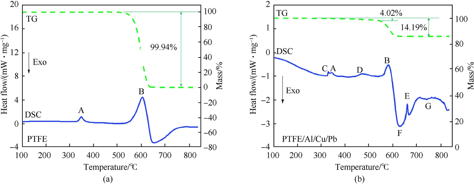
Fig.1.DSC/TG results:(a)PTFE and(b)PTFE/Al/Cu/Pb composites.

These results demonstrate that when Al is in excess in a PTFE/Al/Cu/Pb composite,in addition to the reaction of Al and PTFE decomposition product CF,the excess Al also reacts with Cu to form AlCuinstead of the reaction of Al and C to form AlC.In addition,the reaction also generates amorphous carbon,which can not be detected by XRD.These analyses indicate that for PTFE/Al/Cu/Pb composites with excessive Al contents,the heat of reaction includes not only the heat of reaction between Al and PTFE but also the heat of the intermetallic reaction between excess Al and the Cu powder.
2.3.Preparation process
To offer optimum performance for the reactive liner in terms of density and strength,the fabrication process was studied.The main preparation procedure included powder pretreatment,mixture,cold isostatic pressing,and sintering.
(1)In the pretreatment phase,the PTFE,Al,Cu and Pb powders were respectively dried at 57.2C in a vacuum drying oven for about 24 h[4].
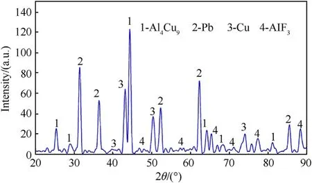
Fig.2.XRD result of solid reaction products of PTFE/Al/Cu/Pb composites.
(2)Then,the mixture phase,a key step in the fabrication procedure,was to begin.As was known that the mixture was influenced significantly by feeding order and mixing method.The mixing process included:①mixing the PTFE powder and the Pb powder together in a ball mill for about 20 min②mixing the PTFE powder,electrolytic Cu powder and atomized Cu powder together in a ball mill for about 40 min③mixing the PTFE powder and Al powder together in a ball mill for about 10 min④mixing the three pre-mixtures above in a ball mill for 2 h to break down the agglomeration of powders.
(3)Cold isostatic pressing was conducted to prepare samples from the mixture.It was noted that the structure design of the liner concentrates on producing reasonable jet properties for a deep penetration.The reactive liner structure is illustrated in Fig.3,in which bis the liner thickness.One of the challenges in the pressing step was to develop a method to press the reactive liner so that it was highly-dense,highlyprecise and highly-reproducible.Thus,a press tool was designed and used,as shown in Fig.4.In order to obtain samples with well distribution and high densification,the bed die was controlled to rotate as the drift moves towardthe die.Fig.5 presents the curve of rotate velocity of bed die vs.the drift displacement of in four stages:for the stages one to three the bed die keeps rotate;for the four stage the bed die keeps unmoved and the press pressure reaches to 400 MPa finally.
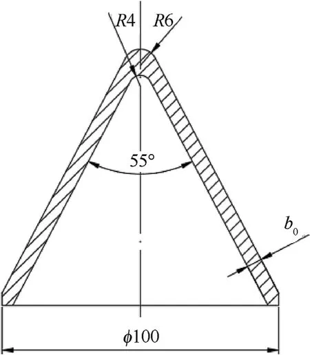
Fig.3.Structure of reactive liner.
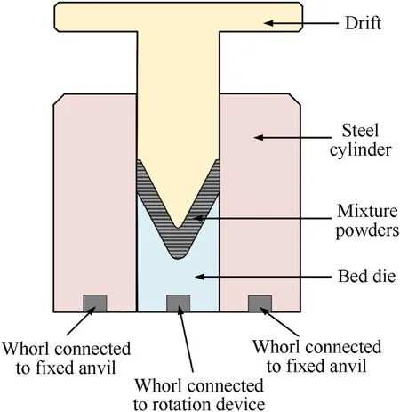
Fig.4.Press tool of reactive liner.
(4)The pressed samples were relaxed at ambient pressure and temperature for 24 h to remove any trapped air and residual stress.Then,the pressed samples were placed into a furnace to undergo a sintering process under the nitrogen atmosphere protection.The sintering history is shown in Fig.6.The oven temperature was raised up to 260C at a rate of about 5C/min,then improved to 380C at a rate of about 0.5C/min,and held at 380C for 4 h.After that,the temperature decreased with a rate of about 0.5C/min to 315C and maintained for 4 h.At last,the furnace was cooled in the ambient temperature and pressure,which costed about 10 h.
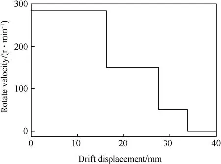
Fig.5.Rotate velocity curve of bed die.
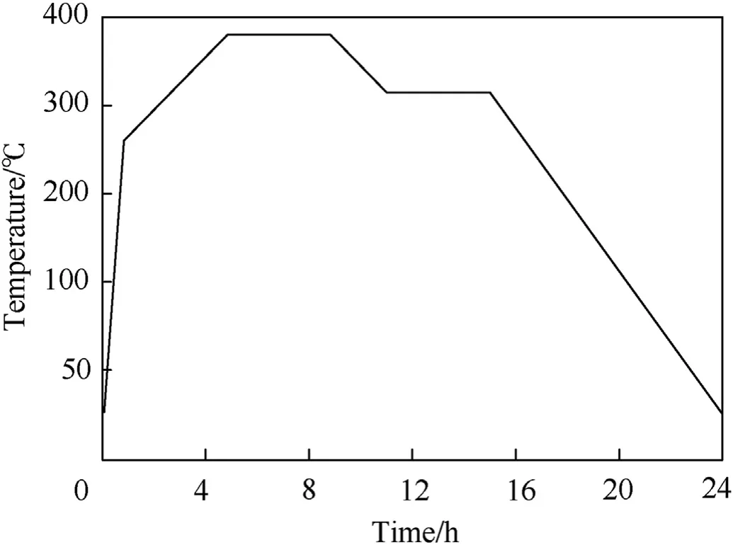
Fig.6.Sintering history curve of liners.
Fig.7 presents a typical pressed and sintered sample of PTFE/Al/Cu/Pb reactive liner,and the performance parameters of these liners are listed in Table 2.The mass and wall thickness of PTFE/Al/Cu/Pb reactive liners were measured by the balance and the micrometer,respectively.The density of the reactive liner was measured by drainage method.The mass of PTFE/Al/Cu/Pb reactive materials was 450 g.After the process of cold pressing and sintering,the average wall thicknesses of the reactive liner samples were 5.120 mm and 5.144 mm,the density of the samples was 5.27 g/cmand 5.245 g/cm,respectively.The results show that the sintering process could produce a slight expansion effects of the pressed reactive liner,but the properties of reactive liners after sintering process are consistent with each other generally.

Table 2Performance parameters of PTFE/Al/Cu/Pb reactive liners.
2.4.Microstructure of samples
In order to evaluate the preparation process characteristics of the PTFE/Al/Cu/Pb reactive liner,the microstructures and elements of the liner samples were analyzed.Fig.8(a)shows the micrograph at the middle part of the sintered liner,and the backscattered scanning electron microscopy(SEM)images of PTFE/Al/Cu/Pb composite are shown in Fig.8(b)~(e).The C element indicates that the PTFE powders are mixed uniformly.The Cu and Pb powders are uniformly distributed in the composites and bonded well with the PTFE matrix,although some gatherings can be found.Compared with the Cu and Pb powders,the Al particle is so large and the Al content is the least,leading to only one Al particle being found inthe view.
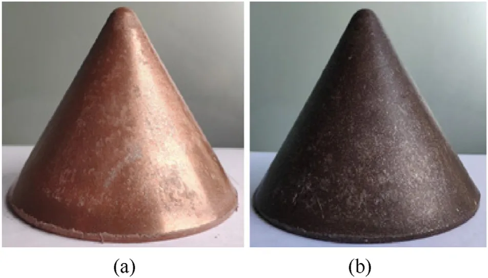
Fig.7.PTFE/Al/Cu/Pb reactive liner:(a)pressed and(b)sintered sample.
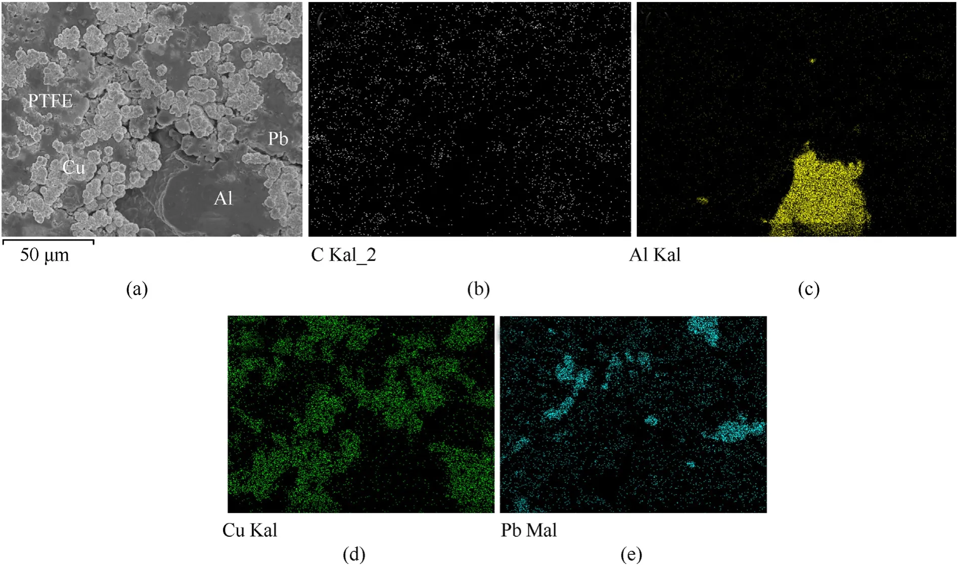
Fig.8.Microstructures and elements distribution of the samples:(a)PTFE/Al/Cu/Pb reactive liner,(b)C element,(c)Al element,(d)Cu element,and(e)Pb element.

Fig.9.SEM images of pressed reactive liner at apex,middle and base.
Moreover,Figs.9 and 10 compare the microstructures between pressed and sintered samples,indicating the sintering process can decrease the porosity greatly.In addition,it can be seen that the particles are much more deformed near the liner apex with a small porosity,whereas the porosity at the base there is much larger.
3.Jet formation experiments
3.1.X-ray experimental setup
Like PTFE/Al reactive materials,the PTFE/Al/Cu/Pb mixture also have the dual attributes of explosive-like energy and metal-likestrength.The PTFE/Al/Cu/Pb reactive liner may be activated under the detonation effects of the shaped charge,and then experience a chemical reaction during the jet formation process,which will affect the penetration performance of the jet against the target.Therefore,it is very necessary to verify whether a PTFE/Al/Cu/Pb liner can effectively form a reactive jet.In this section,the pulse Xray tests were conducted to demonstrate the reactive jet formation and investigate the response of PTFE/Al/Cu/Pb reactive materials.

Fig.10.SEM images of sintered reactive liner at apex,middle and base.
The shaped charge,consisting of a main charge,a reactive liner,and a detonator,is shown in Fig.11.The main charge was JH-2 powder and it was centrally initiated through a detonator at the bottom.It should be noted that the scaled-down X-ray experiment was performed in this section,due to the limitation of TNT equivalent in the experimental site.As such,the charge height was 62 mm,the charge diameter was 48 mm,the charge mass was approximately 130 g,and the charge density was approximately 1.7 g/cm.The PTFE/Al/Cu/Pb reactive liner diameter,cone angle and mass were 48 mm,55and 40 g,respectively.The standoff tube machined by nylon with a height of 450 mm,and it was mainly used to support the shaped charge.
The X-ray test principle and setup are shown in Fig.12.The American HP company X-ray pulse test devices(model 43737)were applied in the experiment.Two channels of flash X-ray system were placed at different positions,and the direction of the rays intersected at the axis of the shaped charge with a certain angle.Two different ray emission delay time were set for the two tubes,so two X radiographs can be taken at two different times[28].
3.2.X-ray experimental results
The typical formation behaviors of PTFE/Al/Cu/Pb reactive jets are shown in Fig.13.Two experiments,and four flash X-radiographs were taken at different time delays:18.6 μs,24.6 μs,32.7 μs,and 38.8 μs,counting from the time of the main charge initiation.Fig.13(a),(b),(c),and(d)show that the positions of four reactive jets reached are approximately 1.0 CD,2.0 CD,3.0 CD,and 4.0 CD of standoff respectively.Based on the formation time and the relative length of reactive jets,the average tip velocity of the PTFE/Al/Cu/Pb reactive jet can be calculated,which is approximately 6700 m/s.
It can be seen from Fig.13(a)and(b)that the PTFE/Al/Cu/Pb reactive jets appear clear,and the boundary of the jet head and the slug also shows clearly.The continuity and symmetry of the reactive jet are excellent,and it maintains a high coaxiality along the detonation axis in Fig.13(b).It should be noted that the poor symmetry of the jet head in Fig.13(a)may be caused by the poor coaxiality between the reactive liner and the main charge(a common error for such test).Moreover,the larger the slug is,the sharper the outline is,and the brighter the imaging color is.This indicates that most of the PTFE/Al/Cu/Pb reactive liner has formed the slug part,resulting in the slug with higher quality and better compactness.Fig.13(a)and(b)also shows that the jet head presents different degrees of divergence and expansion effects at two moments.In addition to the interaction with the bow shock in the air,this is mainly because the reactive liner materials are kind of integrated solid energetic materials prepared by filling metal powders in a high polymer binder(namely PTFE matrix),and itssound velocity is generally lower than 2000 m/s.This property causes the supersonic phenomenon in the formation process of the reactive jet which is driven by the main charge detonation,making the jet diverge radially into much smaller particles.In other words,the head part of reactive jet appears to be not agglomerate,and this phenomenon is also known as“overdriving effect”[29].
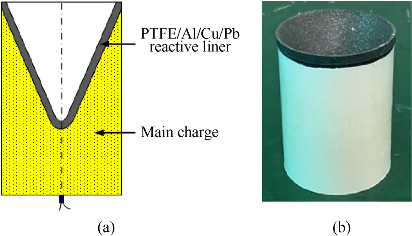
Fig.11.Reactive liner shaped charge:(a)schematic and(b)picture.
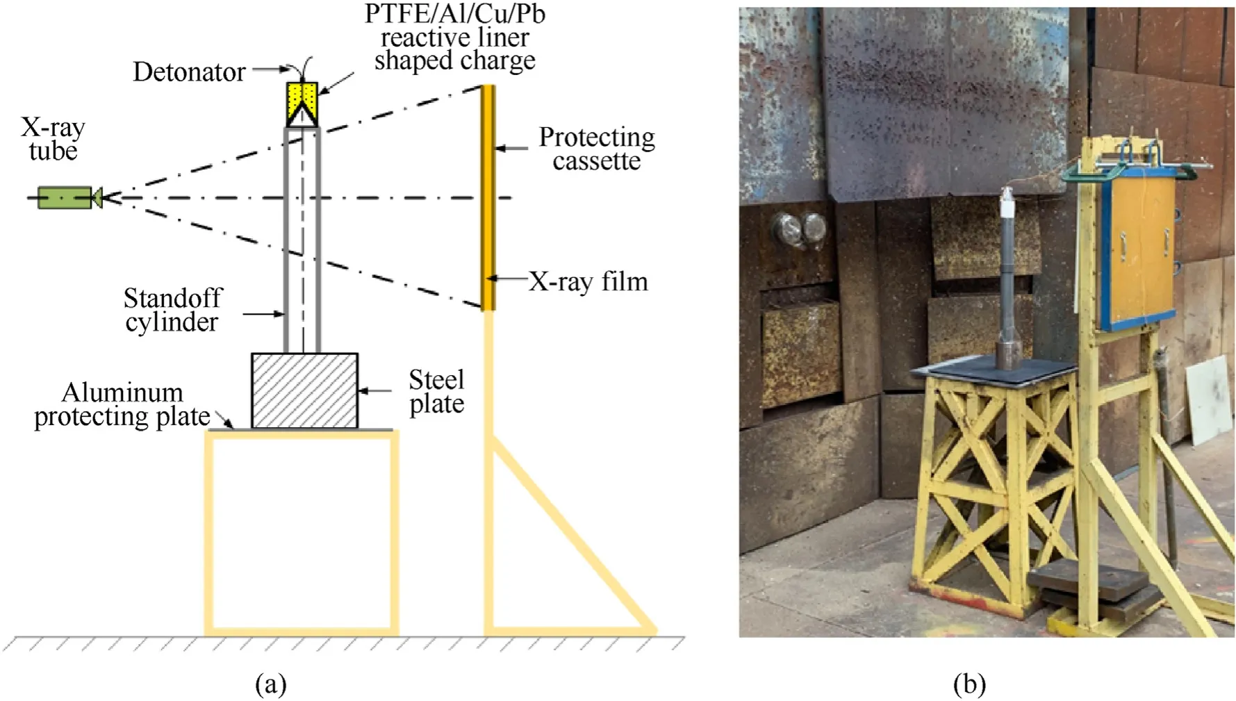
Fig.12.Experimental principle and setup of pulse X-ray:(a)schematic and(b)setup.
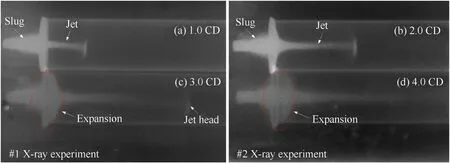
Fig.13.X-ray results of PTFE/Al/Cu/Pb reactive jet formation:(a)t=18.6 μs,(b)t=24.6 μs,(c)t=32.7 μs,and(d)t=38.8 μs?
For the radiographs of Fig.13(c)and(d),the outline of the reactive jet becomes blurry,especially for the jet head,and its boundary can hardly be distinguished with increasing of the formation time.Furthermore,compared with the radiographs at 1.0 CD and 2.0 CD standoff,the diameters of the reactive jets at 3.0 CD and 4.0 CD standoff are significantly larger,especially the connection between the jet and the slug.This phenomenon indicates that the overall expansion of the reactive jet has occurred and its volume has increased,resulting in the decrease of entire density of jet,which is also the reason why the radiographs of 3.0 CD and 4.0 CD standoff is shallower.It should be noted that the higher the jet density,the clearer the X-ray image.
According to the discussions above,this class of PTFE/Al/Cu/Pb reactive liner could form a reactive jet with excellent performance under the shaped charge effects.Especially within the smaller standoff region,the PTFE/Al/Cu/Pb reactive jet has a satisfied continuity,distinct outline,and clear jet tip and rear.The sharp outline of reactive jets indicates that there should be no violent chemical reaction at a standoff of 2.0 CD.However,with the standoff increasing to 3.0 CD and 4.0 CD,the expansion effects of reactive jets demonstrate that a certain degree of chemical reaction may be occurred,which will significantly influence its penetration performance.As such,it is a safe conclusion that the PTFE/Al/Cu/Pb reactive jet is sensitive to the standoff.
4.Jet penetrating experiments
4.1.Experimental setup
The configuration of the shaped charge with a PTFE/Al/Cu/Pb reactive liner is depicted as Fig.14(a).The main charge and vice charge were JH-2 explosive.The JH-2 explosive with a density of 1.7 g/cmhad a height of 200 mm and a diameter of 100 mm.The explosive was initiated by a detonator which was placed on the center of the vice charge.The case was machined by LY12 Al with a thickness of 2 mm.The base diameter of reactive liner was 100 mmand the mass of every liner was approximately 450 g,which was to ensure that the reactive jet could experience a violent deflagration reaction and release a large amount of chemical energy during the penetration process or at the termination of penetration process.
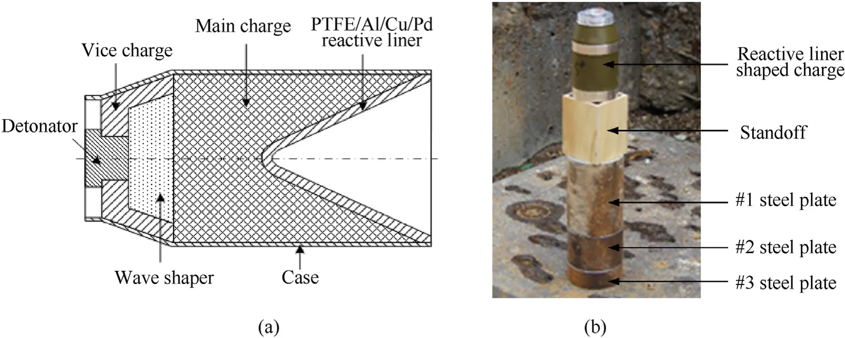
Fig.14.Experimental diagram of PTFE/Al/Cu/Pb reactive liner shaped charge against steel target:(a)Configuration of the shaped charge and(b)Experimental setup.
The diagram of the shaped charge against steel target is shown in Fig.14(b).To facilitate the measurement of the penetration depth and the observation of the follow-through behavior of reactive materials,the steel target composed by three steel plates had a diameter of 130 mm and a total thickness of 350 mm;i.e.,200+100+50 mm.In order to investigate the standoff effects on the penetration performance of PTFE/Al/Cu/Pb reactive jet,wooden standoff tubes of four different heights(0.5,1.0,1.5,and 2.0 CD)were used to adjust the heights from the bottom of the shaped charge to the steel target.
4.2.Results and discussion
The experimental photographs of PTFE/Al/Cu/Pb reactive liner shaped charges penetrating steel targets under different standoffs are shown in Figs.15~18.When the standoff is 0.5 CD,1.0 CD and 1.5 CD,under the combined effect of kinetic and chemical energy of the PTFE/Al/Cu/Pb reactive jet,the 200-mm thick steel plates are broken into several fragments.Some fragments are thrown over 30 m away,some small fragments even cannot be found anywhere.When the standoff is 1.0 CD,although the reactive jet dose not perforate the 100-mm thick steel plates,two cross cracks form at the back center of#2 steel plate under the deflagration reaction of the reactive jet,as seen in Fig.16.When the standoff is 1.5 CD,the reactive jet has perforated #2 steel plate but fails to perforate #3 steel plate,and there are several small cracks at the entrance hole of#2 steel plate,as shown in Fig.17.When the standoff is 2.0 CD,no fragmentation but the cracking damage pattern is formed on #1 steel plate,and there is a throughout crack and some small cracks on the front and back of #1 steel plate,as presented in Fig.18.
These experimental phenomena indicate that the PTFE/Al/Cu/Pb reactive jet can produce violent deflagration reaction inside the target,releasing a large amount of chemical energy and gaseous products,thereby producing overpressure and thermal effects.In fact,the reaction temperature of PTFE and Al can reach more than 3000 K[30],which will lead to the vaporization of Pb powder,also producing the overpressure effect.This vaporization behavior of Pb at high temperature will make the actual quantity of gaseous products much larger than the theoretical value.Under the overpressure effects,the penetrated steel plates show serious fragmentation behavior.However,the damage mode and fragmentation behavior of the targets are markedly influenced by the standoff.With increasing the standoff,the reactive jet is elongated and generally become a thin and long cone penetrator,which leads to a decrease of the penetration hole-diameter and less reactive materials entering into the penetration hole,thus resulting in the deflagration pressure inside the penetration hole dropping off significantly[18].Therefore,when the standoff is 2.0 CD,the deflagration pressure produced by the less mass of reactive materials cannot cause the steel plate with larger wall thickness to rupture,only generating several cracks on the 200-mm thick steel plate.Consequently,a conclusion can be safely drawn that the structural damage effects of steel target formed by the PTFE/Al/Cu/Pb reactive jet generally decrease with an increase of the standoff.
The experimental results of PTFE/Al/Cu/Pb reactive jets penetrating steel targets are summarized in Table 3.With the standoff increasing from 0.5 CD to 2.0 CD,the penetration depth first increases and then decreases.When the standoff is 1.5 CD,the penetration depth of the PTFE/Al/Cu/Pb reactive jet penetrating steel target can reach 3.35 CD.However,for the traditional PTFE/Al reactive jet in reference[18],the penetration depths at the standoff of 0.5,1.0,1.5,and 2.0 CD are 0.93,1.18,1.22,and 0.95 CD,respectively.Thus,the results indicate that,compared with the traditional PTFE/Al jets,the penetration depths of PTFE/Al/Cu/Pb reactive jets significantly increase,as shown in Fig.19.In addition to the influence of the reactive liner diameter and the initiation delay time of reactive materials,there are two other reasons must be considered.On one hand,compared with the PTFE/Al reactive liner with a density of 2.3 g/cm,the density of the PTFE/Al/Cu/Pb reactive liner is higher.On the other hand,the addition of Cu and Pb powder in the basic PTFE/Al formulation system should improve the ductility of the reactive jet.According to reference[31],the combined effects of the higher density and good ductility are beneficial to the jet penetrating the target.As such,when appropriately adds the Cu and Pb powder into the PTFE/Al mixture,the penetration performance of the reactive jet will increase significantly.

Table 3Experimental results of PTFE/Al/Cu/Pb reactive jets penetrating steel targets.

Fig.15.Experimental results of steel plates at 0.5 CD standoff.

Fig.16.Experimental results of steel plates at 1.0 CD standoff.

Fig.17.Experimental results of steel plates at 1.5 CD standoff.
?
5.Conclusions
In this paper,the reaction characteristic of PTFE/Al/Cu/Pb reactive materials were investigated from the thermal analysis and chemical reaction by DSC/TG and XRD techniques.Moreover,the PTFE/Al/Cu/Pb reactive materials application to a shaped charge liner were studied by X-ray and static experiments.The mainconclusions are drawn as follows:
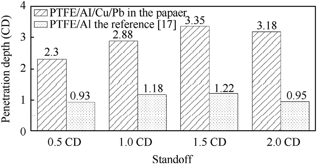
Fig.19.Comparison of the penetration depths of PTFE/Al/Cu/Pb and PTFE/Al reactive jets.
(a)The theoretical reaction heat and gaseous products quantity of PTFE/Al/Cu/Pb(14 wt%/9 wt%/57 wt%/20 wt%)reactive materials were approximately 1724 kJ/kg and 63.3 L/kg,respectively.The DSC/TG and XRD analyses have revealed that for the PTFE/Al/Cu/Pb composites,the actual reaction heat included not only the oxidation reaction between Al and PTFE decomposition product CFbut also the intermetallic reaction between excess Al and Cu powder.
(b)The PTFE/Al/Cu/Pb reactive liners with excellent performance were fabricated by means of powder pretreatment,mixture,cold isostatic pressing,and sintering.The microstructures of the pressed and sintered liner samples indicated that the particles were uniformly distributed in PTFE/Al/Cu/Pb mixture,and the sintering process can significantly decrease the porosity in the reactive liner.
(c)The X-ray experiments demonstrated that the PTFE/Al/Cu/Pb reactive liner could form a reactive jet with excellent performance under the shaped charge effects.However,the PTFE/Al/Cu/Pb reactive jet was sensitive to the standoff.With the standoff increasing to 3.0 CD,the reactive jet should experience a certain degree of chemical reaction,resulting to overall expansion and the density decreasing of the jet.
(d)Compared with the traditional PTFE/Al reactive jet,the experiments showed that PTFE/Al/Cu/Pd reactive jets penetrating steel targets could produce a deeper penetration depth and also accompany with fragmentation effects.The damage modes and fragmentation behaviors of penetrated steel plates were significantly influenced by the standoff.When the standoffs were 0.5 CD,1.0 CD and 1.5 CD,the penetrated 200-mm thick steel plates seriously rupture under the combined effect of kinetic energy and chemical energy of the PTFE/Al/Cu/Pb reactive jet.
The authors declare that they have no known competing financial interests or personal relationships that could have appeared to influence the work reported in this paper.
The research was funded under the National Natural Science Foundation of China(No.12002046),and the study was also supported by the State Key Laboratory of Explosion Science and Technology of China.
杂志排行
Defence Technology的其它文章
- 3D laser scanning strategy based on cascaded deep neural network
- Damage analysis of POZD coated square reinforced concrete slab under contact blast
- Autonomous maneuver decision-making for a UCAV in short-range aerial combat based on an MS-DDQN algorithm
- The properties of Sn—Zn—Al—La fusible alloy for mitigation devices of solid propellant rocket motors
- The surface activation of boron to improve ignition and combustion characteristic
- Numerical investigation on free air blast loads generated from centerinitiated cylindrical charges with varied aspect ratio in arbitrary orientation
