Analysis on damage characteristics and detonation performance of solid rocket engine charge subjected to jet
2022-09-22SonglinPngXiongChenJinshengXuGetuZhoriHongYingDu
Song-lin Png ,Xiong Chen ,Jin-sheng Xu ,*,Ge-tu Zhori ,Hong-Ying Du
a School of Mechanical Engineering,Nanjing University of Science and Technology,Nanjing,210094,China
b The 41st Institute,The Sixth Academy,China Aerospace Science and Industry Corporation,Hohhot,010010,China
c Technology Center,Jinxi Industries Group Company Limited,Taiyuan,030027,China
Keywords:Explosion mechanics Shaped charge jet Damage characteristics Detonation performance of propellant
ABSTRACT To further explore the damage characteristics and impact response of the shaped charge to the solid rocket engine(SRE)in storage or transportation,protective armor was designed and the shelled charges model(SCM)/SRE with protective armor impacting by shaped charge tests were conducted.Air overpressures at 5 locations and axial acceleration caused by the explosion were measured,and the experimental results were compared with two air overpressure curves of propellant detonation obtained by related scholars.Afterwards,the finite element software AUTODYN was used to simulate the SCM impacted process and SRE detonation results.The penetration process and the formation cause of damage were analyzed.The detonation performance of TNT,reference propellant,and the propellant used in this experiment was compared.The axial acceleration caused by the explosion was also analyzed.By comprehensive comparison,the energy released by the detonation of this propellant is larger,and the HMX or Al particles contained in this propellant are more than the reference propellant,with a TNT equivalent of 1.168—1.196.Finally,advanced protection armor suggestions were proposed based on the theory of woven fabric rubber composite armor(WFRCA).
1.Introduction
Solid rocket engines(SREs)with the advantages of high specific impulse and easy to store,are widely used as the power equipment of rockets,missiles and launch vehicles.In order to achieve the higher specific impulse and thrust of SREs,a considerable proportion of HMX,Al particles and other energetic materials are added into Nitrate Ester Plasticized Polyether(NEPE)propellants.The vulnerability improves accordingly,making propellants prone to accidents when they are stimulated to different degrees during storage and transportation.Therefore,low vulnerability standards are proposed for insensitive munition(IM),such as the MIL-STD-2105D[1]of the US Army and the NATO standard for IM[2,3].Among all kinds of external stimuli,the jet impact is considered to be the most serious stimulus[4,5]and also one of the necessary insensitivity tests in national standards[1—3].Relevant scholars have done a lot of research on the characteristics of the jet penetrating finite thickness targets and the jet impacting explosives or propellants that are exposed or are single layer covered[6—11].However,since most of the SREs are transported and stored with storage boxes or launchers,the impacting process evolves into jet penetrating through layers of armor firstly,and then impacting propellants.The process is more similar to the jet impact charge with spaced armors.It is significantly different from jet impacting on exposed engines or propellants,because of the distraction of armors and added impact from armor fragments.Therefore,to ensure that SREs could be better protected during transportation and storage,it is necessary to explore the response of SREs with protective armor subjected to jet and the detonation performance of NEPE propellants.Meanwhile,the process of jet penetration and damage characteristics of SREs should be analyzed to lay a foundation for improving the mechanism of jet impact initiation propellants and SREs.
Related scholars have also made some progresses on jet impact spaced targets and jet impact charges covered with spaced targets.Svirsky et al.[12]studied the interaction between the jet and finite thickness target,as well as spaced targets,and proposed that thereduction of the jet penetration capability is due to the erosion of the front region of the jet having perforated through the target.The authors carried out several modeling of the interaction process and the semi-empirical formula of the jet loss length with good fitting.Liu et al.[13]derived a theory method to describe the residual depth of penetration(DOP)after the jet passes through steel spaced armors.And effects of distance and target thickness of spaced armors on DOP were analyzed.Zhang et al.[14]provided the engineering analysis models of jet precursor wave and residual jet detonating explosive after breaking through spaced targets.They found the jet diameter reduces 22%,and meanwhile it reduces the initiating capacity of the jet.The effect on jet initiating capacity of ammunition shell is larger than that of protective armor.However,the authors did not use experiments to validate their models.
Due to the existence of protective armor,the jet could deflect due to the lateral force from armors or breaks up due to the cutting of the target,or the long flight distance before impacting the engine.In conclusion,the path and effect of the jet impacting are more complicated.Compared with the studies on jet impact shelled or exposed propellants,there are few studies on jet impact rocket engine with protective armor.In addition,among kinds of propellants,NEPE propellant is the highest energy propellant applied in the SRMs in the world[15],the high risk leads to fewer related experiments.The impact response of jet to Double-Based(DB)propellant,Hydroxy-Terminated Polybutadiene(HTPB)propellant and other propellants may not apply to NEPE propellant because of the difference of mechanical properties and detonation properties.Therefore,it is necessary to analyze the impact response of NEPE propellant.
The purpose of this paper is to explore the impact response of SRE with protective armor subjected to shaped charge jet.Therefore,firstly the protective armor was designed according to the existing storage equipment,and two tests,jet impacting shelled charges model(SCM)with protective armor test(SCM Test)and jet impacting solid rocket with protective armor engine(SRE)test(SRE Test)were conducted.The damage characteristics of engine model,response and detonation performance of engine were obtained and analyzed.Afterwards,according to finite element modeling(FEM)software AUTODYN,the jet impact process was simulated numerically to analyze the jet shape change process and the formation reason of the engine damage characteristics.And the detonation performance of TNT,another NEPE propellant as references,and NEPE propellant in this paper were compared by ideal detonation.Finally,advanced protection armor suggestions were proposed based on the theory of woven fabric rubber composite armor(WFRCA).
2.Experimental section
The SCM test system consisted of shaped charge,protective armor,SCM and signal acquisition system.The protective armor was placed between the model and the shaped charge.The distance between armors and the shaped charge was 80 mm to ensure that the shaped charge has the appropriate stand-off.The protective armor and SCM spacing was 205 mm.During the test,the centers of shaped charge,protective armor and SCM were guaranteed to be at the same height.4 wedge-shaped air overpressure sensors were placed at distances of 0.6,1.5,1.5,and 1.5 m from the model center,respectively.
The layout of shaped charge,protective armor and engine in SRE test was consistent with the SCM test,as shown in Fig.1.6 wedgeshaped air overpressure sensors were placed around the engine,to measure the air overpressures during the impact.The distances L from the center of the engine are listed in Tab 1.In the direction of the nozzle of the engine,4 acceleration sensors in a protective device with the same diameter as the engine was designed to simulate the impact acceleration of the rocket warhead during the engine response.The test process was recorded using high-speed camera.
The diameter(CD)of shaped charge was 56 mm and the charge volume of 8701 explosives was 203 g.The oxygen-free high conductivity(OFHC)copper cover had a cone of 60angle with a thickness of 0.8 mm.The reference penetration depth of this shaped charge in Rolled Homogeneous Armor(RHA)at a standoff of 80 mm was 200 mm.The velocity of the jet tip was 6510 m/s,and that of the tail was 1189 m/s[16].The protective armor was constants of 3 layers,with 11.5 mm fiber composite plate,90 mm hard foam and 2 mm aluminum plate.The SCM was loaded with propellant adhesive,as well as sodium chloride instead of HMX and Al particles.The adhesive was used to guarantee the mechanical properties,and sodium chloride was used to avoid that charge combust or explode subjected to jet,so the SCM could be used to replace the solid propellant to verify the penetration and damage characteristics subjected to shaped charge.The engine(φ170 mm×200 mm)was loaded with 4.2 kg of NEPE high-energy solid propellant whose main components were adhesive,Al particles,HMX,etc.The density was 1.867 g/cm.The engine was wrapped with fiber composite material.The sampling frequency of the overpressure sensor was 20 MHz.
3.Experimental results and analysis
3.1.SCM test
The protective armor and SCM after impact are shown in Fig.2.The aluminum plate layer and the composite material layer were all broken down,and the hard foam layer was completely destroyed.There are irregular pits impacted and ablated around the holes by shaped charge cover fragments that have not closed in jet incompletely on the aluminum layer.The diameter of penetration hole on the aluminum layer is about 25 mm,and that on the fiber composite layer is about 16 mm.
The separated SCM to observe the penetration path and damage characteristics are shown in Fig.3.Figs.2 and 3 indicate that the jet can break down completely the protective armor and the engine.The inlet of the hole was 46 mm and the exit of hole was 9 mm on the SCM.After the jet penetrated the protective armor,it collided secondly with the engine model and formed a conical pit with a depth of 37 mm.Comparing the size of holes on SCM and protective armor,the jet got a lateral velocity,leading to twist and disperse in the air,and obtained a larger jet radius.The jet continues at a high velocity to completely penetrate the SCM with the shell,including the carbon fiber composite shell on the other side of the SCM.As it is shown in Fig.3,except for the conical pit generated in the preliminary stage,the diameter of penetration path decreased with the jet penetrating.The exit hole on the propellant was significantly smaller than that on the shell.Since the elasticity modulus of the charge model was higher than hard foam,there was no large deformation on the SCM near the path.Therefore,the propellant model was not destroyed completely like the hard foam,and made the diameter of jet decrease.
The air overpressure curves are shown in Fig.4.Since only the shaped charge detonated in this test,the air overpressure was too small.None of the 3 wedge sensors at 1.5 m measured the ideal air overpressure curve,and the overpressure was almost zero.At a distance of 0.6 m,the air overpressure generated by the detonation of the shaped charge was only about 0.22 MPa.Since in the similar test,compared with the air overpressure generated by the engine charge explosion,the air overpressure generated by the shaped charge is only 5% or even lower in the similar test[6],so itsinfluences in the engine response process can be ignored.
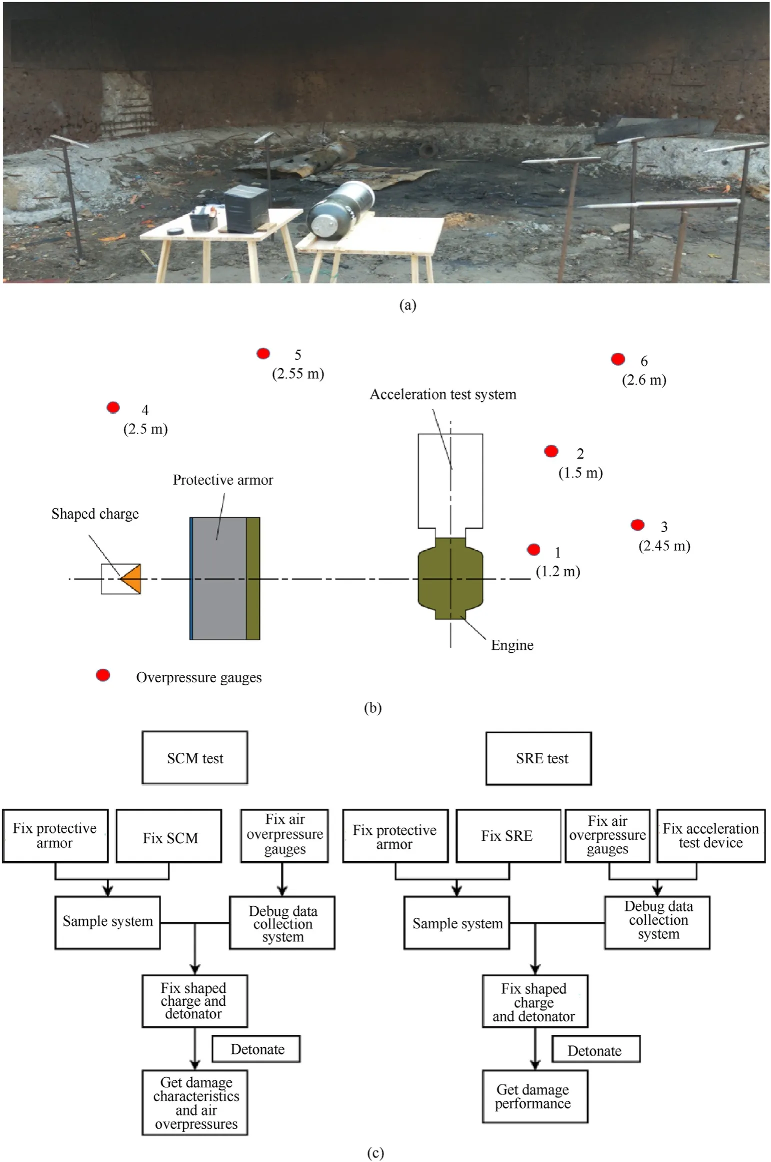
Fig.1.Experimental layout,schematic diagram and flow charts.(a).Experimental layout(b).Schematic diagram and(c).flow charts of tests.
3.2.SRE test
The camera record showed that the engine was completely detonated after being impacted by the shaped charge.6 air overpressure sensors worked normally except the sensor 1# at 1.2 m.The curves of air overpressureΔp are shown in Fig.5.The peaks of Δp and sensors distances L are shown in Table 1.Fig.5 shows that the air overpressure peak decreased 2.075 MPa from 1.5 m to 2.45 m.By observing the peaks in air overpressure curves in Fig.5,it can be seen that the peak at 2.5 m appeared earlier significantly than that of 2.45 m.Besides,the peak of 2.55 m should appear between the peak of 2.45 m and the peak of 2.6 m on the timeline,and nearer the peak of 2.6 m.However,the actual time of 2.55 m is 4.05 ms which is early slightly.According to Fig.1(b),it shows thatsensors 4#at 2.5 m and 5#2.55 m were located on the side near the shaped charge,so this side was preferentially impacted by the metal jet and generated the shock wave with stable attenuation in the air earlier compared with the other side.

Table 1Parameters in SRE test.
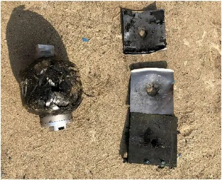
Fig.2.Protective armor and SCM after impacting.

Fig.3.Penetration path in separated SCM.
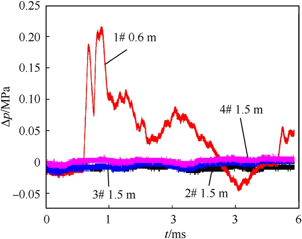
Fig.4.Air overpressure curves in SCM test.
It is worth noting that theΔp peaks occurred at about 5.5—6 ms secondly in the air overpressure curve in Fig.5.It can be ruled out that it is the second wave peak caused by interval initiation or double points initiation.The interval time of the two peaks was about 1.25—2 ms.In general,the C-J velocity of the explosion in the charge is 3000—8000 m/s and the detonation process takes about a few μs,which is inconsistent with the interval time between the two peaks.And more,the jet velocity is 1100—7000 m/s,and the flight distance of the jet should be more than 2.2 m within 2 ms.It obviously contradicts the experimental phenomenon.
The propagation path of the shock wave is shown in Fig.6.The distance difference of path 1 and path 1is 1.33 m,and that of path 2 and path 2is 0.7 m.According to the time and sensors’locations,it indicates that the average steady propagation velocity of the detonation wave is 356.8 m/s.Therefore,at 1.5 m and 2.5 m,the calculated peak time difference is about 3.73 ms and 1.96 ms,respectively.It can be observed that the 2# sensor at 1.5 m measured the first peak at 1 ms,and the air overpressure rose again in 4.5—5 ms.After measuring the first peak in 3.5—4.5 ms,sensor 3#-6# from 2.45 m to 2.6 m showed a second peak almost equivalent to the first peak in 5—5.75 ms.It demonstrates that shock waves reflected off the ground cause the double peaks in air overpressure curves.
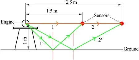
Fig.6.The propagation path of the shock wave.
Yang and Li[17,18]have done some researches on TNT equivalence of 2 kinds of high energy propellants,one of which was NEPE propellant,and another was unknown.They fitted the pressure formulas of high energy propellants based on the airborne explosion experiment results,as follows:


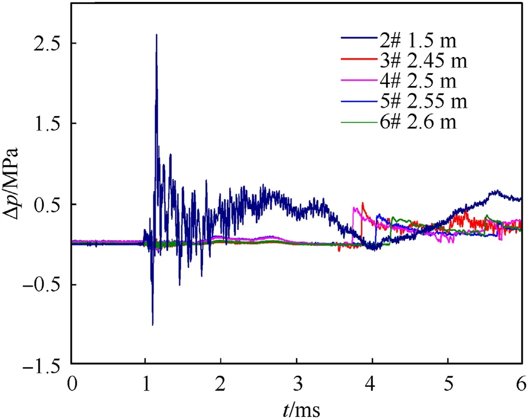
Fig.5.Air overpressure curves of impacting engine test.
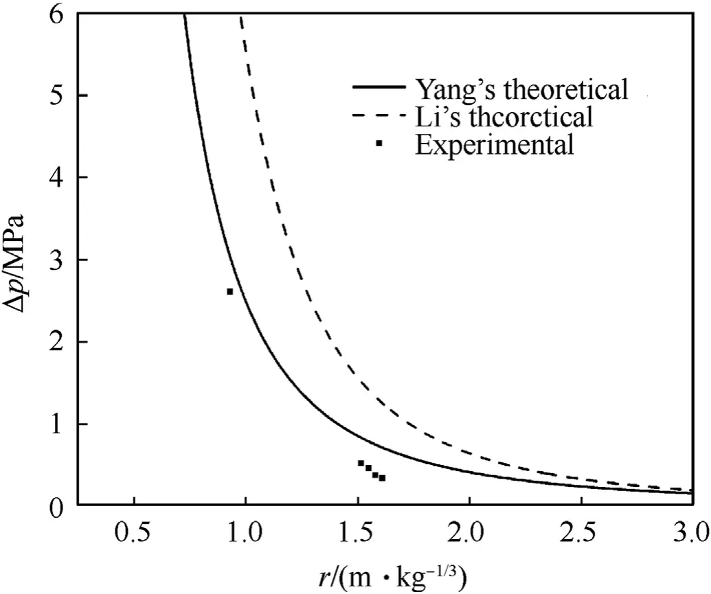
Fig.7.Comparison of experimental data and theoretical function curves.
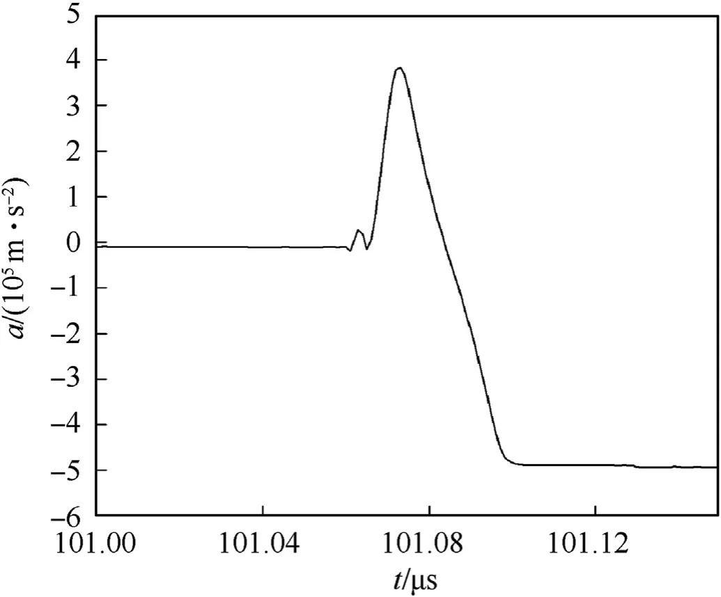
Fig.8.Acceleration curve of impacting engine test.
The axial acceleration curve measured by the acceleration sensors at the moment of explosion is shown in Fig.8.When the engine exploded violently,the acceleration sensor device used to simulate the warhead was thrown out.The 25 mm steel cylinder wall close to the engine was completely cracked,the top cover was separated from the cylinder body,and the fixing sensors in cylinder were thrown out.The debris is shown in Fig.9.According to the observation of acceleration curve,it can be found that the peak value of axial acceleration a received by the sensor was 3.82×10m/swithin 10 μs,and then negative reverse acceleration was generated due to the device being thrown out and hitting the ground or wall,and the sensor broke down due to the circuit and other reasons.The total weight of the sensor measuring device was 20 kg and the pressed area was 2.27×10m.According to Newton's second law F=M∙a and pressure formula P=F/S,the peak impact force F was 7.64×10N and the peak pressure P was 0.34 GPa.However,the detonation pressure of high energy propellants generally is more than 20 GPa[19,20].It indicates that the pressure was not fully applied to the acceleration of the warhead.Measuring devices connected to the engine firmly,and part of the shock wave pressure dissipated by engine shell burst,and further,part of the pressure in this direction dissipated through breaking the steel cylinder wall.Therefore,the impact detonation pressureacting on the acceleration sensor was much lower than that of the propellant explosion itself.And more,the measuring devices were blown up while acceleration was in the process of rising.Because of the fall and collision,the acceleration was reversed,and the sensors of the test device were destroyed.So the measured acceleration did not completely reach the peak in the test.
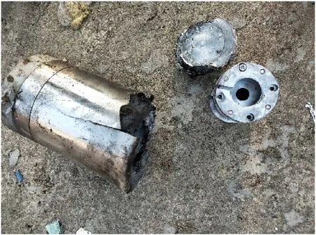
Fig.9.Debris of acceleration test system after the explosion.
4.Numerical simulation analysis
4.1.Analysis of morphological characteristics
FEM software AUTODYN was used to simulate the test process of SCM test,and the penetration path of the metal jet was further analyzed.The whole simulation process was divided into two parts:firstly,the 2D axisymmetric 1/2 shaped charge FEM was constructed to generate the metal jet FEM,and secondly through the 2D-3D mapping function of AUTODYN,the metal jet FEM was imported into the 3D 1/2 model to simulate the process of impact protection armor and SCM.
4.1.1.Finite element models and materials
The shaped charge FEM is shown in Fig.10.Due to the large deformation of the material,Euler grids were used,Cu-OFHC was selected as the material of the cover,and the Shock equation of state(EOS)and Steinberg Guinan strength model were used to describe the constitutive relationship.The state of 8701 explosive adopted JWL equation[12]:


Fig.10.The FEM for shaped-charge.
where P is the pressure of detonation product,Pa.V is the relative specific volume of detonation products;Eis the initial volume energy,J/mor Pa;A,B,R,R,ω are constants,and values were taken as A=854.5 GPa,B=20.493 GPa,R=4.6、R=1.35、ω=0.25[13].
According to the metal jet formed by the 2D shaped charge FEM,as shown in Fig.11(a),it indicates that the jet was formed at 21.26 μs,reaching the stand-off of 80 mm,and was ready to impact the target.The diameter of the jet tip is about 0.88 mm and the maximum diameter of the jet tail is about 8.7 mm.The maximum diameter of the pestle is about 9 mm.The average velocity of the jet tip is about 7088 m/s,and the average velocity of the jet tail is about 1138 m/s.At the same time,due to the difference in the closing speed of the shaped charge cover particles,the closure has not been completed completely.There are lots of residual annular shaped charge cover fragments with both axial and radial velocity around the jet,which will import it,or impact the target.Fig.11(b)shows that the constructed 3D 1/2 model of the metal jet,which was mapped to the 3D model,protective armor and SCM.The material model selections for each layer of protective armor and SCM are shown in Table 2.Since the mechanical properties of the rubber material are similar to those of the propellant in the SRE test,with mechanical properties such as tension-compression asymmetry and anisotropy,as well as the visco-hyperelastic properties of the polymer,it could be used to replace the solid propellant to verify the penetration and damage characteristics subjected to shaped charge.The grids were divided by Lagrange grid.The grids of shell and charge were divided by ICEM CFD software,and then imported into AUTODYN to generate the high quality grids.Since the Hyperelastic model could not use a structured grid,the SCM used unstructured grids.

Table 2Material models for protective armor and charge.
4.1.2.Analysis of simulation result
The numerical simulation results of penetration are shown in Fig.12.As shown in Fig.12(a),the incomplete closure fragments of the charge cover resulted in a larger hole diameter of 2.05 cm for the aluminum compartment that was firstly impacted.And the expansion of the hard foam layer because of the impact,led to the whole aluminum layer protruding slightly outward.After the hard foam was impacted,due to its softer material and smaller elastic modulus(about 700 MPa)compared with metal,hard foam suffered greater damage.As the aperture was penetrated,the material as a whole presents a trend of expansion and tearing in all directions.The velocity of the whole hard foam is shown as Fig.12(b).From 10 μs to 25 μs,the increase in velocity of hard foam was from jet penetration.As the penetration path had formed,jet was no longer in contact with the hard foam,not providing acceleration.After 52 μs,the pestle began to penetrate the hard foam,and formed a larger hole.Expansion velocity was increased again.Therefore,in the test,the foam layer was completely destroyed because of the expansion velocity.The hole size produced by the Kevlar layer is 1.35 cm.
As shown in Fig.12(c),when the jet head was penetrating the protective armor before 23 μs,the jet was at a fairly high stress level,and the jet head presents a mushroom-like deformation.Under this deformation,the jet head consumed its energy to overcome the resistance of the target and generate a hole.The jet itself also produced deflection and torsional deformation in some directions due to its interaction with the protective armor.The lateral velocity peak of jet was 87 m/s.Some particles collided with the wall of the hole,causing energy consumption and DOP decrease[21].After penetrating the protective armor at 25 μs,the mushroom-like deformation still existed,and the mushroom-like head appeared outward expanding deformation due to the sudden unloading of the jet under high pressure.The expansion of jet head caused extra energy loss[12].With the increase of the jetheight,the jet of breaking occurred due to the velocity difference of each part.At the same time,it is obvious that deflection and torsional deformation of jet was more and more serious after 37 μs.
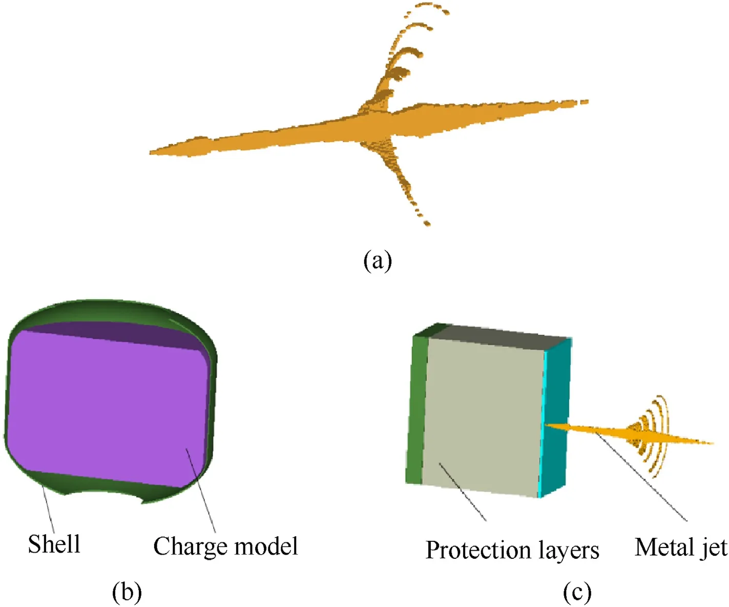
Fig.11.The FEM of SCM test.(a).Metal jet and(b).Overall model.
As shown in Fig.13,a second impact occurred between the jet and the SCM.A conical pit with a diameter of 4.75 cm and a depth of 3.2 cm was produced on the SCM by mushroom shaped heads of jet together with some scattered jet fragments.The pit diameter of the shell is about 4.45 cm,smaller than that of the SCM,due to the ultra-high strength and good toughness of the Kevlar material because of the close bonding of chemical bonds in the molecules.Subsequently,the mushroom-like head was eroded by impact and high temperature,and the jet was also eroded by high temperature,high speed and energy dissipation,leaving little mass,which was almost similar to the erosion of the pill.And velocity decreased greatly and the average velocity of the jet was about 2570 m/s.Therefore,it continued to penetrate the charge column until it was completely penetrated out,and the aperture did not show an increasing trend.
4.2.Analysis of a NEPE propellant detonation performance
Since there is no specific component ratio of the NEPE highenergy propellant,the overpressure values of air at various distances measured in the test were compared with the overpressure value of reference NEPE propellant with known components and explosives such as TNT during complete detonation,to evaluate its detonation performance.In addition,when the engine was impacted and detonated,the impact effect of the warhead suffered was simulated to verify acceleration in the test.
4.2.1.Finite element models and materials
A 2D 1/2 axisymmetric model of ideal engine complete detonation is shown in Fig.14.The acceleration test device was connected to the upper cover,and the material was Steel 4340.The Linear EOS and Johnson Cook strength model were used to describe the mechanical properties of the material.10 gauge points were set to measure the air overpressures at the same distances as those in the test(2 gauge points in different directions for each distance).The acceleration test device shell and covers were divided by Lagrange grids,while the propellant and air domain were divided by Euler grids.The size of the air domain was 600 mm×2600 mm,and the grid density was distributed in a gradual grid.The air domain near the engine was densely distributed,and the grid density gradually decreased with the increase of the distance.The number of grids was 600×1500,a total of 900,000.TNT and reference NEPE high-energy solid propellant(mass fraction of HMX 36%,oxidant AP 20%,and Al particles 18%—20%)which were described by JWL EOS,were respectively selected for the charge,and the parameters are shown in Table 3[22].
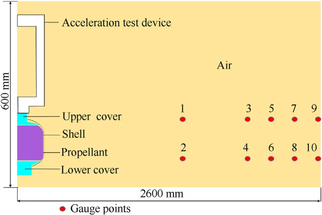
Fig.14.The FEM of ideal detonation with the rocket engine.
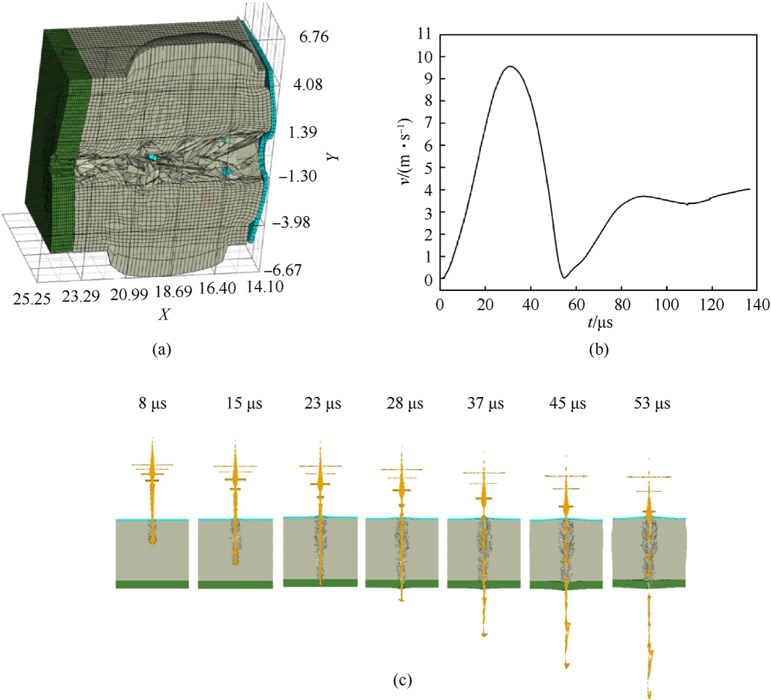
Fig.12.The damage characteristics of protective armor.(a).Protective armor damaged;(b)velocity of hard foam expansion;and(c)the process of the jet stretching and penetrating the protection layer.
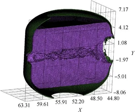
Fig.13.The damage characteristics of impacted SCM.
4.2.2.Simulation results and analysis
The comparison between the peak and average values of air overpressures at Gauge points of the three charges and the experiment values is shown in Table 4.Table 4 proves that the test peak at 1.5 m of air overpressure is about 1.168—1.196 times that generated by TNT of the same mass,and at the same time,is 5.25%—5.64% higher than that of reference propellant.However,at a distance of 2.55 m—2.6 m,the test peak of air overpressure is a few lower than that of the reference propellant.The results show that the short distance detonation performance of the propellant is better than that of the reference propellant.Considering the actualand 7.46×10m/s,respectively.Since there are no obstacles in the air domain during the simulation process,there will be no collision between the device and other objects.Compared with the simulation results and the previous process of analysis,it can be concluded that the peak acceleration obtained from the test wasconditions of the test,there are air temperature,humidity,as well as the site reflection,refraction and other reasons in the far distance,so that the explosion shock wave produced more attenuation.And more,at a relatively long distance,the pressure of the shock wave is close to atmospheric pressure,that is 0.101 MPa,which is disturbed easily and causes errors.Compared with the air domain selected by numerical simulation as ideal gas,there are fewer factors to be considered and the attenuation of the shock wave is smaller.Therefore,a higher peak of air overpressure could be obtained at a longer distance.

Table 3Parameters of charges using JWL EOS.

Table 4Comparison of air overpressure peaks and experimental air overpressure peaks at Gauges.

Table 5Sensitivity constants of explosives.
By comprehensive comparison of the three kinds of energetic materials with the same mass,it can be concluded that the energy released by the detonation of this propellant is larger,and the HMX or Al particles contained in this propellant is more than the reference propellant,with a TNT equivalent of 1.168—1.196.
TNT and another propellant were used for ideal detonation simulation,and the acceleration curve of the whole device of the acceleration test system was shown in Fig.15.According to the simulation results,the peak acceleration generated by TNT and the reference propellant on the simulated warhead is 6.52×10m/slower than the actual acceleration,and the acceleration process was not finished due to the explosion and collision.Combined with the TNT equivalent of the NEPE propellant,the acceleration generated by the propellant explosion on a 20 kg simulated warhead should be in the range of 7.615×10-7.833×10m/s.
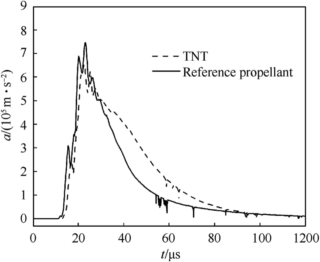
Fig.15.Acceleration curve of the acceleration test system by numerical simulating.
5.Advanced protection armor
5.1.Structure of advanced armor
In order to decrease the damage from shaped charge jet,additional armor which leads to interaction between the jet and the inclined moving plate is a normal way to interfere with the metal jet.Explosive reactive armor(ERA),as additional armor,has been demonstrated to be one of the most effective against jets.But it may cause damage to the surrounding environment[23],while propellants are easy to craze,dewetting(the filler particles and matrix debonding)and other damages under vibration,and even combustion or sympathetic detonation under shock wave.So,nonexplosive bulging reactive armor is an ideal method to improve its jet protection ability.
At present,woven fabric reinforced composites are among the most important and widely used forms of ballistic impact-resistant and armor protection materials[16].Jia et al.[16,24—26]have made considerable experimental and theoretical progresses on the woven fabric rubber composite armor(WFRCA)against jet.In terms of the choice of fabric types,comparing the four woven fabrics,Kevlar WFRCA has a better anti-penetration performance that can reduce DOP by at least 63.5%[16].Regarding jet penetration Angle,the X-ray experiment showed that when the penetration angle is 60,the interference effect is better,and the velocity of the escaped precursor is lower.The length of the precursor is 130 mm,with the head velocity of 5300 m/s,the tail velocity of 3750 m/s.The remaining DOP on RHA is 73 mm[26].
To sum up,in this paper,Kevlar WFRCA is selected as the additional armor and insert into the hard foam layer of the original armor.Kevlar WFRCA consists of RHA,Kevlar and rubber and the structure of it is shown as Fig.16(a).In the protective armor,the hard foam is mainly to insulate temperature and to cushion vibration.Many studies have proved that temperature has an obvious influence on the mechanical properties of solid propellants[27—29].It is worth being retained.In addition,the original singlelayer 11.5 mm fiber composite armor was modified to a thickness ofRHA to reduce the penetration of the precursor.The structure is shown in Fig.16(b).
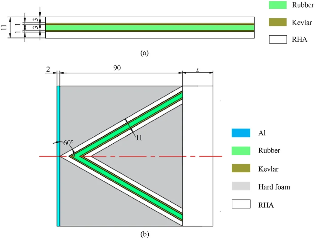
Fig.16.The advanced protective armor.(a).The structure of Kelar WFRCA and(b).The overall structure of armor.
5.2.Verification of RHA thickness
Held proposed the criteria for explosive initiation[30]:

where vis the velocity of the jet head,d is the diameter of the jet,and K is the sensitivity constant of the explosive.Table 5 lists the sensitivity constants of several explosives.According to the research of scholars on response characteristics on shell solid propellants under bullet impact[31],the response of reference NEPE propellant in this paper under bullet is the deflagration.The diameter of bullets is 12.7 mm,and the velocity is 845—860 m/s.Therefore,the sensitivity constant K value of the reference NEPE propellant is not less than 9.068×10.The jet diameter is about 2.5 mm,so the NEPE propellant critical velocity of detonation is about 1904.5 m/s.Under the action of WFRCA armor,the jet will be divided into three sections:precursor,disturbance area and tail slug,as shown Fig.17 from Ref.[16].The velocity of the precursor is higher,but the diameter is smaller.The disturbance area has almost no penetration ability.The velocity of the tail slug is about 1100 m/s.Although the diameter is bigger than the jet,the velocity is not high enough to penetrate deeply.According to NATO STANAG 4439-2010[3],the response includes 5 grades:I.Detonation,II.Partial detonation,III.Explosion,Ⅳ.Deflagration andⅤ.Burning.Therefore,if the advanced structure could reduce the response grade to deflagration,the risk will reduce greatly compared with using the original armor.Combined with the weight and space of the additional armor,the additional RHA armor is to consume the precursor instead of the whole jet.
DOP of the precursor was verified by AUTODYN software.The model is shown in Fig.18(a).The head and tail velocities of the precursor were 5533 m/s and 3340 m/s,respectively.And the RHA thickness was 80 mm.Shock EOS and Von Mises mechanical model were used to describe the RHA.The penetration result is shown in Fig.18(b),and the penetration depth is 57.6 mm.In a word,the RHA thickness of advanced armor should be at least 58 mm.

Fig.17.The disturbance effect of WFRCA X-ray graph from Ref.[16].
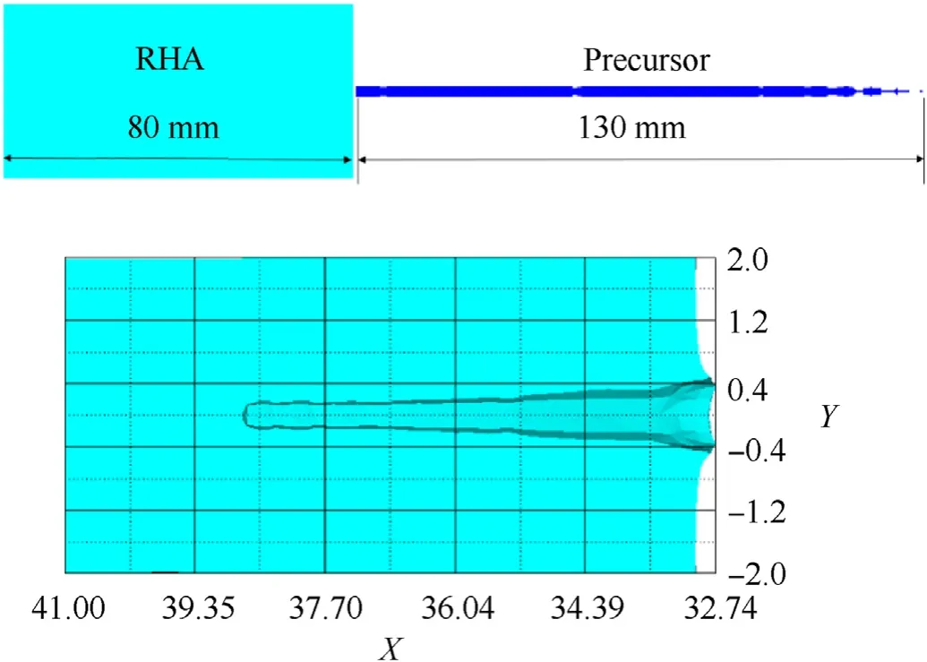
Fig.18.Simulation and verification.(a).The FEM of precursor and RHA and(b).The result of penetration.
6.Conclusion
In this paper,to explore the response of SRE with protective armor to jet,the protective armor was designed according to the existing storage equipment,SCM Test and SRE Test were conducted.The damage characteristics of the engine model,response and detonation performance of the engine were obtained and analyzed.Afterwards,according to FEM software AUTODYN,the jet impact process was simulated numerically to analyze the jet shape change process and the formation reason of the engine damage characteristics.And the detonation performance of TNT,another NEPE propellant as a reference and NEPE propellant in this paper were compared by ideal detonation.The acceleration process of the simulated warhead was analyzed.Finally,advanced protection armor suggestions were proposed based on the theory of WFRCA.The conclusions of this study can be summarized as follows:
(1)The experimental results show that the metal jet completely penetrated the protective armor and the shelled charges model,and 4.2 kg of shelled propellant was completely detonated after being impacted by the jet.The peak of air overpressure at 1.5 m was about 2.605 MPa.The acceleration of 3.82×10m/son the simulated warhead was measured in the test.
(2)The decreasing trend of air overpressures experiment values is consistent with the theoretical curves,and compared with theoretical curves,the experiment values are both lower than the theoretical values at the same distances.There were two peaks in air overpressure curves.According to the analysis of several possible results,it is determined that the cause is the superposition of direct incident overpressure and ground reflected overpressure.
(3)During the process of impact,from 10 μs to 25 μs,the increase in velocity of hard foam was from jet penetration and led to hard foam destroy.Some particles collided with the wall of the hole,causing energy consumption and depth of penetration to decrease.After penetrating the protective armor at 25 μs,the mushroom-like deformation still existed,and it is obvious that deflection and torsional deformation of the jet was more and more serious after 37 μs.The lateral velocity peak of the jet was 87 m/s.
(4)By comprehensive comparison of the three kinds of energetic materials with the same mass,the energy released by the detonation of this propellant is larger,and the HMX or Al particles contained in this propellant is more than the reference propellant,with a TNT equivalent of 1.168—1.196.And in the test,the acceleration process of the simulated warhead was not finished due to the explosion and collision.Combined with the TNT equivalent of the NEPE propellant,the acceleration generated by the propellant explosion on a 20 kg simulated warhead should be in the range of 7.615×10-7.833×10m/s.
(5)Kevlar WFRCA is selected as the additional armor and insert into the hard foam layer of the original armor.In addition,the original single-layer 11.5 mm fiber composite armor was modified to a thickness of RHA to reduce the penetration of the precursor.The RHA thickness of advanced armor should be at least 58 mm,which can reduce the response toⅣ.Deflagration.
The authors declare that they have no known competing financial interests or personal relationships that could have appeared to influence the work reported in this paper.
杂志排行
Defence Technology的其它文章
- Ballistic response of armour plates using Generative Adversarial Networks
- Vulnerability assessment to projectiles:Approach definition and application to helicopter platforms
- Shock initiation performance of NTO-based polymer bonded explosive
- Thermal hazard assessment of TKX-50-based melt-cast explosive
- A bayesian optimisation methodology for the inverse derivation of viscoplasticity model constants in high strain-rate simulations
- Reaction characteristic of PTFE/Al/Cu/Pb composites and application in shaped charge liner
