Commissioning of laser electron gamma beamline SLEGS at SSRF
2022-09-02HongWeiWangGongTaoFanLongXiangLiuHangHuaXuWenQingShenYuGangMaHiroakiUtsunomiyaLongLongSongXiGuangCaoZiRuiHaoKaiJieChenShengJinYuXuanYangXinRongHuXinXiangLiPanKuang
Hong-Wei Wang• Gong-Tao Fan • Long-Xiang Liu • Hang-Hua Xu •Wen-Qing Shen • Yu-Gang Ma• Hiroaki Utsunomiya • Long-Long Song •Xi-Guang Cao • Zi-Rui Hao • Kai-Jie Chen • Sheng Jin • Yu-Xuan Yang •Xin-Rong Hu • Xin-Xiang Li • Pan Kuang
Abstract The Shanghai Laser Electron Gamma Source(SLEGS) is a powerful gamma source that provides MeV gamma-ray beams for nuclear science and technology. It was developed as one of the 16 beamline stations in the Phase II Project of the Shanghai Synchrotron Radiation Facility. The slant-scattering mode is for the first time systematically employed in laser Compton scattering at SLEGS to produce energy-tunable quasi-monoenergetic gamma-ray beams. The SLEGS officially completed its commissioning from July to December 2021. Gamma rays in the energy range of 0.25-21.7 MeV with a flux of 2.1 × 10⁴-1.2 × 10⁷ photons/s and an energy spread of 2-15% were produced during the test. This paper reports the results from commissioning the SLEGS beamline.
Keywords SLEGS · Laser Compton scattering · Slantscattering mode · Backscattering mode
1 Introduction
Photonuclear reactions form a unique field of nuclear physics and astrophysics because of their well-known electromagnetic interactions. As early as the 1960s and through the 1980s, the systematic study of the isovector giant dipole resonance was carried out in photoneutron cross-sectional measurements with a wide range of nuclei at the Saclay Laboratory,France,and Lawrence Livermore National Laboratory(LLNL),USA,using positron in-flight annihilation technology. However, a large discrepancy between the Saclay and LLNL data regarding the photoneutron cross sections has persisted [1-5], leading to the creation of the International Atomic Energy Agency(IAEA) photonuclear data library in 2019, which includes new data to resolve the long-standing discrepancy [3].
The laser Compton scattering(LCS)gamma source was developed based on the inverse Compton scattering of laser photons from relativistic electrons in the storage ring. It is currently the most advanced quasi-monoenergetic gammaray source and provides a new research opportunity to study photonuclear physics. Since the 1980s, the LCS beamline [6] of the National Institute of Advanced Industrial Science Technology (AIST) and the NewSUBARU BL01 LCS beamline of the University of Hyogo, both in Japan [7], as well as the high-intensity gamma source(HIγS) of the Triangle University Nuclear Laboratory(TUNL) in the USA, have been constructed to study nuclear physics[8].The high-energy laser electron gamma source (LEGS) at the Stanford Linear Accelerator Center(SLAC)[9]and the laser electron photon beamline(LEPS/LEPS2) at SPring-8 are dedicated to hadron physics [10].The TERAS LCS beamline was closed in 2013; after the installation of a new injection linac, and the operation of the NewSUBARU LCS beamline is currently limited to industrial applications. Currently, only the high-energy LPES/LEPS2 and low-energy HIγS are in operation as major facilities. The laser electron gamma source the variable energy gamma-ray (VEGA) system in extreme light infrastructure-nuclear physics (ELI-NP) was redesigned in 2019, is currently under construction, and is scheduled to begin operation in 2023 [11].
The Shanghai Laser Electron Gamma Source (SLEGS)was first proposed in 1998 at the Shanghai Synchrotron Radiation Facility (SSRF). Nearly 20 years after the feasibility study and prototype development [12-19], it was approved in 2016 as one of the 16 beamlines in the Phase II project of the SSRF by the National Development and Reform Commission, People’s Republic of China. Construction of the SLEGS beamline began in October 2019 and was completed in December 2021. The beamline passed the commissioning test in 2021 and will be open to users by the end of 2022 [20].
Using a CO2laser with a wavelength of 10.64 μm and a maximum power of 100 W, high-intensity gamma-ray beams are generated in collisions with 3.5 GeV electrons in the SSRF storage ring. The SLEGS is designed to operate in two operating modes: One is the laser Compton backscattering mode at 180°, which is commonly used around the world to achieve the highest energy and polarization of gamma-ray beams;and the other is the laser Compton slant-scattering mode, which enables the energy of gamma-ray beams to be tuned by changing the collision angle between the laser and electron beams in a wide range, from 20° to 160°.
Slant scattering is a key technology for producing energy-tunable gamma-ray beams at synchrotron radiation facilities operating at a fixed electron beam energy. In the past decade,SINAP-II[15-19]and UVSOR-II have played a pioneering role in the technical development of slant scattering. While UVSOR-II has succeeded in producing MeV gamma rays at limited slant-scattering angles ranging from 70°to 110°[21,22],the gamma-ray beam production at SLEGS is systematically carried out in an innovative manner with a dedicated interaction chamber [23] and double collimator system [24, 25].
2 Research at SLEGS
SLEGS is designed to generate gamma-ray beams at energies ranging from 0.25 to 21.1 MeV in slant scattering at collision angles ranging from 20° to 160° and at a maximum energy of 21.7 MeV in backscattering at 180°. The full-spectrum flux ranges from ~105photons/s at 20° to ~107at 180°. A 2% energy resolution is achieved with a 1- to 2-mm collimator, which confines the emission angle of the gamma-ray beam to less than 0.5 mrad.
The SLEGS serves as a multi-functional experimental platform for research in nuclear science and technology[20]. The research spectrum in basic research ranges from collective excitation of nuclei, nuclear equations of state,and the origin of elements to ultra-high-energy cosmic rays,while that in application research ranges from atomic energy, nuclear transmutation, and gamma imaging to national security.
3 SLEGS beamline
The SLEGS beamline is equipped with four main components,as illustrated in Fig. 1.The SLEGS is located in the BL03SSID of the SSRF experimental hall. A 3D drawing is provided in Fig. 2.

Fig. 1 (Color online) Schematic layout of the SLEGS beamline

Fig. 2 (Color online) 3D drawing of the SLEGS beamline. Top: Interaction chamber (a), multi-functional chamber (b), and coarse collimator (c) inside the SSRF vault. Bottom: Fine collimator(d), flux attenuator (e),experimental detector (f), and gamma absorber (g) in the SLEGS beamline

Fig. 3 (Color online)Schematic of configuration of optical elements (a) and the rotating bracket (b)
(1) 100-W CO2laser [26] and laser transport.
(2) Interaction chamber for slant scattering and multifunctional chamber for backscattering.
(3) Two-stage coarse and fine collimators and gamma flux attenuator.
(4) Experimental hutch, experimental detector, gamma absorber, and data acquisition system
3.1 Laser transport and gamma production
A continuous-wave 10.64 μm CO2laser with a laser power of 100 W is located in the laser hutc h located adjacent to the SSRF vault. The hutch is designed as a clean room for stable operation of the laser.The CO2laser can also be operated in pulse mode with an adjustable laser interval and pulse width, e.g., a 1-ms laser interval and 100-μs pulse width at 10 W with a 10% duty cycle.
Collisions between the 10.64 μm laser photons and 3.5 GeV electrons occur inside the interaction chamber,as shown in Fig. 3, in two collision modes: laser Compton backscattering and slant scattering. The CO2laser beam passes through the multi-functional chamber with a ZnSe window,is bent by 90°through a water-cooled mirror,and undergoes a head-on collision in the backscattering mode.In contrast, the laser beam vertically enters the interaction chamber, passes through the optical elements (mirrors m4,m3,m2,and m1and convex lens f1,as shown in Fig. 3),and horizontally collides with the electron beam in the slantscattering mode.The CO2laser is finally refocused and led to beam absorber G through mirror m0and convex lens f0.The optical elements are mounted on a rotating bracket so that the collision angle between the laser and electron beams can be changed from 20° to 160° through a safety stop angle at 90° [23].
3.2 Coarse and fine collimators

Fig.4 (Color online)CAD Drawings(top)and photographs(bottom)of the SLEGS coarse collimator(a),fine collimator(b),flux attenuator(c),and localized shielding (d)
The energy spread and spot size of the gamma-ray beams at the target position are determined by the twostage coarse and fine collimator system, as shown in Fig. 4a,b.The coarse collimator is a revolver type made of 300-mm-thick Pb, located ~18 m away from the gamma production point inside the interaction chamber and separated from the high-vacuum SSRF with a 150-μm Be window.It has 10 fixed holes with apertures of 0,1,2,3,4,5, 8, 10, 20, and 30 mm. The fine collimator is a camera shutter type, which is located 36 m away from the gamma production point in the optical hutch and consists of four sets of shielding shutters, each made of 50-mm tungstencopper alloy(W 80% +Cu 20%).The first and second sets of shutters are rotated around the beam axis by 30°,shaping the beam spot into a regular dodecagon [24, 25].The aperture of the fine collimator can be changed continuously from 0 to 40 mm.
3.3 Flux attenuator
The flux of gamma-ray beams is regulated by an attenuator consisting of eight pieces of oxygen-free copper blocks with diameters of 50 mm, thicknesses of 15 mm,25 mm, 50 mm (two pieces), 100 mm (three pieces), and 200 mm, and a total thickness of 640 mm, as shown in Fig. 4c.Localized shielding around the fine collimator and flux attenuator is shown in Fig. 4d.
3.4 Control system
Figure 5a, b shows the interface displays used to remotely control the coarse and fine collimators, respectively. One of the 10 apertures of the coarse collimator is selected, and the aperture of the fine collimator can be continuously changed in the range of 0-40 mm. The horizontal and vertical positions of the coarse and fine collimators can be adjusted with 0.1 mm precision. Figure 5c shows the interface display for selecting any combination of flux attenuator blocks. The movement of the 200-mm and 100-mm blocks of the flux attenuator is monitored with the CCD camera. Figure 5d shows the control display of the laser system to be tuned for the laser Compton backand slant scatterings. The operating conditions of the CO2laser in the pulse mode are shown in the monitor display,including the pulse interval and width.

Fig. 5 (Color online) Interface displays for the coarse collimator (a), fine collimator (b), flux attenuator (c), and CO2 laser (d)
4 Commissioning of the SLEGS beamline
Measurements of the gamma-ray beams during the commissioning of the SLEGS beamline were taken in an experimental hutch. At the end of the beamline, unreacted gamma rays entered the gamma absorber,which is made of thick concrete, Pb, and high-density polyethylene, as shown in Fig. 1.
4.1 Collimator alignment
The collimators must be aligned with respect to the gamma-ray beam axis. The collimator alignment was performed horizontally and vertically by maximizing the intensity of the gamma rays passing through the collimator.Figure 6a, b shows the gamma-ray intensity as a function of the vertical and horizontal positions of the coarse collimator, respectively. In this collimator position scan, a coarse collimator with an aperture of 2 mm was used along with a 20-mm fine collimator and a 100-mm flux attenuator. A Φ3′′× 4′′(Φ76.2 mm × 101.6 mm) LaBr3(Ce)detector [27] was used to measure the gamma rays. The optimized position of the coarse collimator was found to be(51.97± 0.04) mm vertically and (34.54± 0.03) mm horizontally. The laser electron collision position and fine collimator underwent the same adjustment process.
4.2 Gamma-ray beam spot
The SLEGS beamline is equipped with two beam spot monitors in the experimental hutch (Fig. 7): an X-ray camera called MiniPIX [28], shown in Fig. 7b, and a gamma spot monitor (GSM), shown in Fig. 7d. The MiniPIX consists of 256 × 256 silicon pixels with a pixel size of 55 μm × 55 μm and a silicon wafer thickness of 500 μm. The GSM involves a LYSO scintillator that is 70 mm in diameter and has a thickness of 2.5 mm, which collects the scintillation light generated by X- and gamma rays with a CCD/CMOS camera through a 45° plane mirror, with a 135° optical path as a reserved monitoring channel.

Fig. 6 Results for the vertical (a) and horizontal (b) scans of the coarse collimator

Fig. 7 (Color online) Bremsstrahlung beam spot (a) and MiniPIX (b) inset, gamma beam spot (c) and GSM (d) inset, and photograph of MiniPIX and GSM (e) in the experimental hutch
Figure 7a shows an example of a beam spot with a Bremsstrahlung background measured using MiniPIX.Figure 7c shows an example of the gamma beam spot measured with the GSM after subtracting the Bremsstrahlung background along with the horizontal (X) and vertical(Y)distributions.The gamma beam spot size in the full width at the tenth maximum (FWTM) is horizontally 17.31 mm and vertically 8.91 mm. Because the GSM is placed approximately 38 m from the gamma production point, the calculated gamma-ray emission angles are 0.46 mrad in the X direction and 0.25 mrad in the Y direction.
4.3 Energy profile and flux of gamma-ray beams
A Saint-Gobain lanthanum bromide (LaBr3(Ce)) detector 3′′(76.2 mm) in diameter and 4′′(101.6 mm) in length with an energy resolution of approximately ~3% at 661 keV [27] was used as the energy profile and flux monitor detector in the commissioning run. A BGO detector 76.2 mm in diameter with a length of 200 mm from SICCAS [29], located in the gamma absorber, was used to monitor the gamma flux. The flux value was fed back to the control system of the collimator and laser for online recording and display and will be used for automatic correction of laser power output in the future. Figure 8a shows a typical response function of the LaBr3(Ce)detector with respect to the gamma-ray beam, where a 3-mm coarse collimator, 3-mm fine collimator, and 1-mm additional lead external collimator were used, but without the flux attenuator. The background gamma spectrum is shown by the green line, where the lower-energy synchrotron radiation and higher-energy Bremsstrahlung are seen, as well as internal radiation from138La in the LaBr3(Ce) detector. Figure 8b shows the background-subtracted spectra measured at 20°, 90°, and 180°.
We systematically measured the response functions of the LaBr3(Ce) detector to gamma-ray beams produced by slant scattering. The background-subtracted spectra are shown in Fig. 9. The gamma-ray energy follows the kinematics of laser Compton slant scattering. The production of gamma-ray beams was confirmed in the energy range of 0.25-21.1 MeV in slant-scattering mode from 20°to 160° and at 21.7 MeV in backscattering at 180°.

Fig.8 (Color online)Typical response function of the LaBr3(Ce)detector to a gamma-ray beam(a)and background-subtracted spectra at 20°,90°, and 180° (b)

Fig. 9 (Color online) Response functions of the LaBr3(Ce) detector to gamma-ray beams produced in the slant-scattering mode and background gamma rays to be subtracted.The inset is a comparison of the angle and energy measurements with the theoretically calculated curves
The total gamma-ray flux is an important parameter in the commissioning of the SLEGS beamline. The gamma flux required to be approved is the total flux at the gamma production point integrated over the entire gamma energy spectrum for the electron beam current Ie= 300 mA (design value). The background-free gamma-ray flux ϕ was measured using a LaBr3(Ce) detector at Ie= 200 mA (test value). After normalizing the measured flux ϕ by F = ϕ/[ηD× ηA× ηC] × [300 mA/200 mA] with the detection efficiency ηDof the LaBr3(Ce) detector, transmission rate ηAof the attenuator, and transmission rate ηCof the collimator hole, the total flux is shown in Fig. 10. The maximum flux at an electron current of 300 mA and a laser power of 100 W can reach approximately 105photons/s at 20° and 108photons/s at 180°.
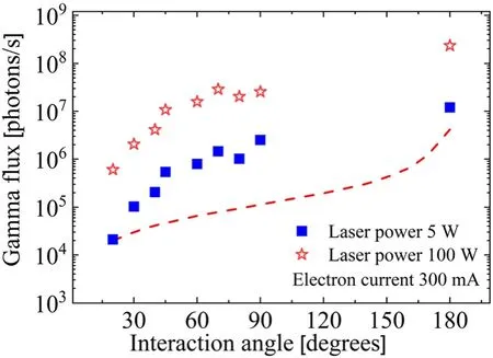
Fig.10 Total gamma flux at the production point.The red dotted line is the theoretical calculated value with a 5 W laser and 300 mA electron current
4.4 Energy distribution of gamma-ray beams
The electron beam energy of the SSRF storage ring is 3.5 GeV. Because of this high electron beam energy, the energy of the gamma-ray beams produced in the laser Compton scattering strongly depends on the emission angle. Thus, the energy spread (resolution) of the gammaray beam is highly sensitive to the angular acceptance,defined by the collimator aperture. The black line in Fig. 11 shows the experimental response function of the LaBr3(Ce) detector to gamma rays produced in backscattering at 180°.Assuming that the energy distribution of the gamma-ray beam incident on the detector is given by a truncated Breit-Wigner function,which is indicated by the blue line, we performed a Geant4 simulation of the response function of the LaBr3(Ce)detector to the gammaray beam. The results are indicated by the red line in Fig. 11. It is clear that the Geant4 simulation reproduces the experimental response function well (black line).Phenomenologically, as the scattering angle decreases in slant-scattering mode, the incident gamma-ray spectra of the Gaussian function better fit the experimental response function in the Geant4 [30] simulation. In this phenomenological study, it was found that an energy resolution of 2-15%could be obtained with a collimator aperture of 1-3 mm.
A thorough study of the energy resolution of the gamma-ray beam requires more realistic Geant4 simulations, in which gamma-ray beams are kinematically produced in laser Compton scattering,transported through the collimator system,and incident on the LaBr3(Ce) detector.The energy distribution of the gamma-ray beam produced in laser Compton scattering depends on the electron beam emittance,which is an important parameter for reproducing the experimental response function. A thorough analysis using more realistic Geant4 simulations will be conducted in the near future.
4.5 Experimental spectrometers
We have developed four types of experimental spectrometers (sometimes called detector arrays), as shown in Fig. 12: a gamma nuclear resonance fluorescence (NRF)spectrometer, neutron flat-efficiency detector (FED) spectrometer, neutron time-of-flight (TOF) spectrometer, and light charged particle (LCP) spectrometer. The four experimental spectrometers are used for the photon elastic/inelastic scattering reaction, photoneutron reaction, and photolight charged particle reaction, respectively. The spectrometer for the photofission reaction is not involved in the current construction stage. The photonuclear reaction experiment can also employ a combination of two spectrometers, such as FED combined with an NRF spectrometer,which will be used in the(γ,nγ)experiment[31].

Fig. 11 (Color online)Experimental response function of the LaBr3(Ce) detector to a gamma-ray beam produced in backscattering mode at 180°(black line), a truncated Breit-Wigner function (blue line)assumed for the energy distribution of the gamma-ray beam, and a Geant4 simulation of the LaBr3(Ce) response function (red line) to the gamma-ray beam (blue line)
The NRF gamma spectrometer consists of two largevolume coaxial HPGe detectors, two clover HPGe detectors [32], and eight 3′′(76.2 mm) × 4′′(101.6 mm)LaBr3(Ce) detectors [28]. The neutron FED consists of twenty-six3He counters [33] embedded in a polyethylene moderator[34]. The TOF neutron spectrometer consists of twenty Φ5′′(127 mm) × 2′′(50.8 mm) EJ301 [35] liquid scintillation detectors. The LCP (p,d,t,α) spectrometer consists of 4-6 groups E-E telescope detectors comprising a grid ionization chamber (GIC)[36],silicon strip detector(SSD) [37], and CsI (Tl) crystal [36] mounted in a large high-vacuum experimental chamber,as shown in Fig. 12d.
5 Results of the commissioning of the SLEGS beamline
The SLEGS beamline started the first test run at a small electron beam current of 10 mA in July 2021 and finished the debugging of the gamma beam generation in the backand slant-scattering modes at 200 mA.The performance of the SLEGS beamline in generating gamma-ray beams and the experimental spectrometer was approved by the Chinese Academy of Sciences (CAS) [38] in December 2021,completing the construction of the SLEGS beamline station.The results obtained during the commissioning run are summarized in Table 1.
Table 2 shows the situation of several LCS facilities worldwide and a comparison of the main gamma parameters. Currently, only HIγS and SLEGS can provide MeV gamma rays for nuclear physics research.
6 Summary and prospects
The completion of the SLEGS beamline station was approved by the Chinese Academy of Sciences (CAS) in December 2021 after the successful commissioning run.Gamma-ray beams are produced in the energy range from 0.25 to 21.1 MeV in the laser Compton slant-scattering mode with 10.64 μm CO2laser photons at scattering angles from 20° to 160°, and at a maximum energy of 21.7 MeV in laser Compton backscattering mode at 180°. The slantscattering mode is employed in the SLEGS beamline to systematically produce gamma-ray beams.

Fig. 12 (Color online) Four types of experimental spectrometers available in the SLEGS experimental station: gamma nuclear resonance fluorescence spectrometer (a), neutron flat-efficiency detector spectrometer (b), neutron time-of-flight spectrometer (c),and light charged particle spectrometer (d)
Two-stage coarse and fine collimators are used to produce fine pencil-like quasi-monochromatic gamma-ray beams. The gamma-ray integrated flux is 2.1 × 10⁴photons/s at 20°, 2.5 × 10⁶photons/s at 90°, and 1.2 × 10⁷photons/s at 180°. The energy spread of the gamma-ray beam is 2 -15% when the gamma-ray emission angle is confined to less than 0.45 mrad at 38 m using the collimator system.Four types of spectrometers,which may reflect the versatility of nuclear physics experiments[39-44], are available at the SLEGS experimental station.The SLEGS beamline will be open to users by the end of 2022. In recent years, some large nuclear scientific facilities have started construction and been put into operation,including the back-streaming neutron (Back-n) source[45, 46] at the China Spallation Neutron Source (CSNS),the High-Intensity Heavy-ion Accelerator Facility (HIAF)[47-49] and CSR External-target Experiment (CEE) [50],Collinear Laser Spectroscopy (CLS)[51, 52], and the newBeijing Radioactive Ion-beam Facility (BRIF) [53]. The completion of these facilities or devices will surely push China’s nuclear physics basic and applied research to the next level.
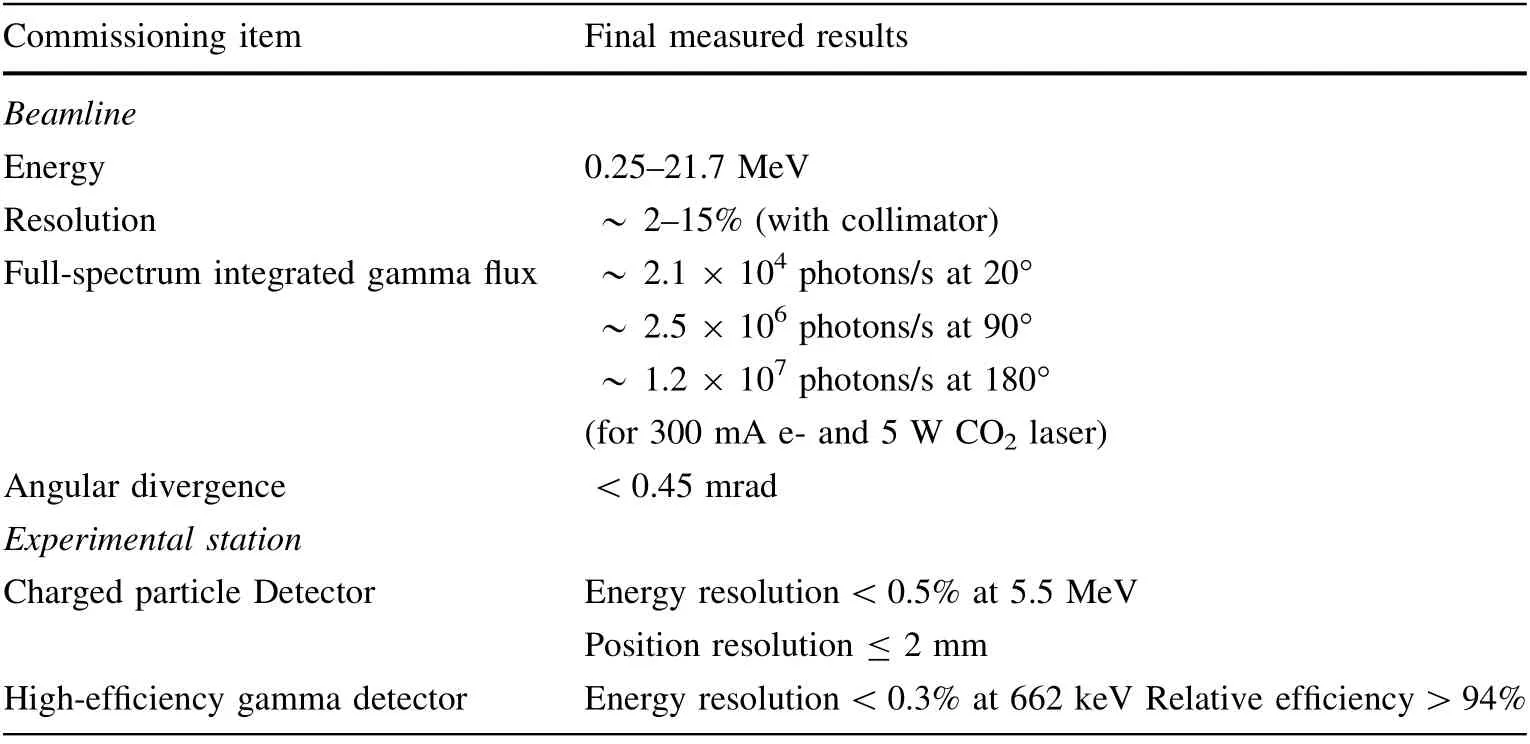
Table 1 Commissioning results for SLEGS

Table 2 Current operation of LCS facilities around the world
AcknowledgementsThe authors thank the SSRF leaders Zhen-Tang Zhao (Academician), Ren-Zhong Tai, and managers and chief engineers Ai-Guo Li, Yong-Bin Leng, Jie Wang, Yu-Ying Huang, Song Xue,Wen-Zhi Zhang,Bo-Cheng Jiang,and Wan-Qian Zhu,as well as other colleagues in the accelerator department and the beamline engineering department of the SSRF for their technical support and assistance.
Open Access This article is licensed under a Creative Commons Attribution 4.0 International License, which permits use, sharing,adaptation,distribution and reproduction in any medium or format,as long as you give appropriate credit to the original author(s) and the source,provide a link to the Creative Commons licence,and indicate if changes were made.The images or other third party material in this article are included in the article’s Creative Commons licence,unless indicated otherwise in a credit line to the material. If material is not included in the article’s Creative Commons licence and your intended use is not permitted by statutory regulation or exceeds the permitted use, you will need to obtain permission directly from the copyright holder. To view a copy of this licence, visit http://creativecommons.org/licenses/by/4.0/.
Author contributionsAll authors contributed to the study conception and design.Material preparation,and data collection and analysis were performed by Long-Xiang Liu, Hang-Hua Xu, Long-Long -Song, Xi-Guang Cao, Zi-Rui Hao, Kai-Jie Chen, Sheng Jin, Yu-Xuan Yang, Xin-Rong Hu, Xin-Xiang Li, and Pan Kuang. More scientific guidance by Wen-Qing Shen and Yu-Gang Ma. The first draft of the manuscript was written by Hong-Wei Wang, Gong-Tao Fan, and Hiroaki Utsunomiya, and all authors commented on previous versions of the manuscript. All authors read and approved the final manuscript.
杂志排行
Nuclear Science and Techniques的其它文章
- Determining absolute value of thermal neutron flux density based on monocrystalline silicon in nuclear reactors
- Transition edge sensor-based detector: from X-ray to γ-ray
- Graded composition and doping p-i-n AlxGa1-xAs/GaAs detector for unbiased voltage operation
- Imaging internal density structure of the Laoheishan volcanic cone with cosmic ray muon radiography
- Silicon PIN photodiode applied to acquire high-frequency sampling XAFS spectra
- Improvement of machine learning-based vertex reconstruction for large liquid scintillator detectors with multiple types of PMTs