Low-radioactivity ultrasonic hydrophone used in positioning system for Jiangmen Underground Neutrino Observatory
2022-07-26DuoTengJiangLaiLiuGuoLeiZhuYueMengYuanyuanZhangTaoZhangKaiLuoRuiLiJiaQiHui
Duo Teng • Jiang-Lai Liu • Guo-Lei Zhu• Yue Meng• Yuan-yuan Zhang •Tao Zhang • Kai Luo • Rui Li • Jia-Qi Hui
Abstract To satisfy the accurate positioning requirement of the calibration source in the Jiangmen Underground Neutrino Observatory, a Tonpilz-type hydrophone with low radioactivity and high electroacoustics is developed.The radioactivity of the proposed hydrophone is strictly controlled by selecting pure raw materials, especially active piezoelectric ceramics. The electroacoustic performance of the hydrophone is improved by making structural optimization. High sensitivity and aimed directivity are achieved using 33-mode piezoelectric ceramic rings arranged in series and improvement in the radiating head of the Tonpilz hydrophone, respectively. All electroacoustic performances are studied through finite element analyses.The simulations indicate that the electroacoustic performances of the hydrophones in linear alkylbenzene-based liquid scintillator can be approximately predicted according to the results in water because their differences caused by two types of acoustic media, water and liquid scintillator, are known. The tests show that the hydrophone prototype can achieve a maximum sensitivity of - 209.3 dB and a beamwidth of 132.2° at a frequency of 143 kHz.In addition, eight hydrophones only contributed to a background radioactivity level of 26 ± 4 mHz in the neutrino analysis.
Keywords JUNO ∙Liquid scintillator ∙Tonpilz hydrophone ∙Low radioactivity ∙Sensitivity ∙Directivity ∙Finite element
1 Introduction
The Jiangmen Underground Neutrino Observatory(JUNO), located in Guangdong Province, China, is being developed to study the fundamental properties of neutrinos and detect neutrinos of different origins [1–5]. The JUNO central detector (CD) consists of a 20-kton linear alkylbenzene-based liquid scintillator, which is enclosed in an acrylic sphere with a 35.4-m inner diameter and a 120-mm thickness, viewed by about 17,600 20-inch and 25,600 3-inch photomultiplier tubes. The CD was immersed in a cylindrical ultrapure water pool with at least 2 m of water from any direction to shield the surrounding radioactivity.
To reconstruct neutrino events accurately,it is critical to calibrate the energy and position responses of the CD. A multicomponent calibration system was developed to deploy radioactive or light sources into designated locations in the CD [6, 7]. Two components, namely the cable loop system [8] and remotely operated vehicle [9], are designed to move the source along the central plane and among the entire detector, respectively. For both systems,the feedback of the source position was provided by a dedicated ultrasonic positioning system, with an absolute positioning accuracy of approximately 3 cm throughout the CD [10]. This system consists of eight hydrophones that are fixed on the inner surface of the CD and immersed in a liquid scintillator throughout the lifetime of JUNO, as shown in Fig. 1. These hydrophones are employed to receive ultrasonic waves from an electroacoustic projector attached to the source. Based on the time difference of the arrival method [11], the position of the source can be geometrically calculated using the distances between the source and no less than three hydrophones. The main requirements of these hydrophones are summarized below[12].
• Electroacoustics.
• Operating frequency and response delay. The positioning accuracy of the ultrasonic wave is related to the wavelength of the wave. A shorter wavelength corresponds to higher positioning accuracy. Considering a positioning accuracy of ~3 cm, a high frequency of ~150 kHz is chosen.Furthermore, a small response delay of no more than one-third of the cycle is required [13].
• Sensitivity. During ultrasonic positioning, the high frequencies of acoustic waves will lead to a large transmitting loss,which will weaken the intensity of the primary signal. After the calculation, a hydrophone with a high sensitivity with no less than -212 dB is required.
• Directivity. According to the location of the hydrophones [11], a hydrophone with a broad beamwidth is required, but it should not be omnidirectional. More precisely, the beamwidth is expected to be large in half-space, but not larger than 180°to block reflected waves from the acrylic sphere. Therefore, a Tonpilz-type hydrophone was studied instead of a thin-walled piezoelectric hollow-sphere transducer [14, 15].
• Radioactivity. To measure rare events from neutrinos,the radioactivity level of hydrophones should be kept low. Quantitatively, it is necessary for hydrophones to contribute <1% of the total radioactive background,i.e., ≤50 mHz background trigger rate of238U/232Th/40K in the fiducial volume [16].
• Liquid scintillator proof. The hydrophone encapsulation should be chemically compatible and physically sealed in a liquid scintillator for 20 years.
The remainder of this paper is organized as follows. In Sect. 2, the design and analysis of the ultrasonic Tonpilz hydrophone (UTH) are described. In Sect. 3, we present performance tests and discussions, followed by a conclusion in Sect. 4.

Fig. 1 (Color online) a Sketch of ultrasonic positioning system in JUNO. b Sensitive region for one hydrophone
2 Design and analysis of UTH
2.1 Structure
The term ‘‘Tonpilz’’ means ‘‘singing mushroom’’ in German. A typical Tonpilz transducer consists of a drive stack, radiating head, tail mass, prestressed bolt, and other accessories [17]. A UTH sketch is shown in Fig. 2(a).Where L represents the length, D represents the diameter,and the subscripts T, I, P, H corresponds to the tail, insulator, piezoelectric stack and head respectively. A drive stack is typically formed by gluing piezoelectric ceramic rings (PCRs) together in series; all of the PCRs are poled along the thickness direction. Generally, even pieces of PCRs are electrically wired in parallel for a high transmitting voltage response when used as a projector,whereas several pieces of PCRs are wired in series to achieve high sensitivity when used as a hydrophone [18]. For the UTH used in JUNO, its drive stack is formed by one piece of thick PCR, which can achieve the same sensitivity as several pieces of thin PCRs in series for a certain length.A prestressed bolt passes through the hole of the PCR to fasten the drive stack to the radiating head and tail mass.Overall,the UTH had a maximum diameter of 8 mm and a length of 10.4 mm. Details pertaining to materials and sizes of each part are summarized in Table 1.
For acoustical insulation between the housing and hydrophone, the UTH is covered by rigid polyurethane foam,except for the radiating head.The geometrical center of its circular end face with a diameter of only 5 mm is the equivalent acoustic center for sensing acoustic signals.When acoustic waves are received by the radiating head,the UTH will be forced to resonate, and the vibration is then transformed into an electrical signal by the PCR [20].
To achieve tightness of the hydrophone in the liquid scintillator,the UTH was encapsulated in a nickel housing,as shown in Fig. 2(b). The back of the housing was filled with epoxy resin, whereas the head of the housing was sealed with a silastic O-ring. Both the epoxy resin and O-ring were found to be chemically compatible with a liquid scintillator. The nickel housing provided good corrosion resistance and excellent electromagnetic shielding characteristics for the UTH. In addition, to minimize the effect of the O-ring piston seal on the ultra-weak vibration of the UTH induced by acoustic waves, a squeeze of 20%was applied to the O-ring, leading to minimal acoustic losses at the head-housing interface [21].
2.2 Vibration
Currently, the finite element method (FEM) is a commonly employed method for transducer design [22]. The design and electroacoustic performance of the UTH were determined based on the FEM.Figure 3 illustrates the finite element model used to simulate the UTH. The in-water model shown in Fig. 3(a) includes 14,138 nodes and 12,850 elements. Each part of the UTH is denoted by a different color, and the details of the dimensions and materials are summarized in Table 1.Such a finite element model is very similar to a realistic transducer.

Fig. 2 (Color online) a Drawing of the JUNO UTH; b Drawing of a sealed UTH assembly

Table 1 Material and size of components of UTH

Fig. 3 (Color online) In-water finite element model of UTH.a 1/16 symmetrical finite element model in water for solution; b 3/4 model for structure specification
Figure 4(a) illustrates the vibration mode shape at the modal frequency of 145.25 kHz, which is the resonance frequency of the transducer. The vector illustration of vibration indicates that vibration is longitudinal, which is consistent with the polarization direction of the PCR. This 33-mode longitudinal vibrator of the PCR will make the highest electromechanical coupling, resulting in high sensitivity. The vibration produced by the head is 2.03 times stronger than that produced by the tail.This distribution of vibration indicates that the head is the part of UTH that is sensitive to acoustic waves.In addition,the contour plot of vibration displacements on the radiating face of the UTH in Fig. 4(b)shows that the ratio of the minimum to maximum vibration amplitude exceeds 0.989, indicating a piston vibrating on the radiating face of the UTH. Similar results are obtained for the UTH immersed in liquid scintillator.
2.3 Admittance
The simulated admittance curves of UTH in water and in the linear alkylbenzene-based liquid scintillator are shown in Fig. 5. The conductance, G, and susceptance, B,of the UTH in the two different acoustic media are similar.The conductance peak represents the resonance of the UTH.The maximum G is 182.9 μS@145.25 kHz in water,and it is 195.9 μS@145.75 kHz in linear alkylbenzenebased liquid scintillator. The slight drifts in the conductance and resonance frequency are due to the different acoustic media.

Fig.4 (Color online)a Vector illustration of vibration of the UTH in water(f = 145.25 kHz).b Contour plot of vibration displacements on the radiating face of the UTH

Fig. 5 (Color online) Admittance curves in water and in linear alkylbenzene-based liquid scintillator (obtained from FEM)
2.4 Sensitivity
The receiving capability of a hydrophone [23] is typically characterized by the ratio of the open-circuit voltage,V, to the acoustic pressure in water, pf.
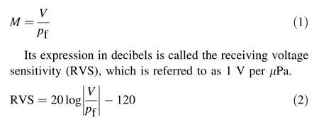
To obtain a high sensitivity, a hydrophone operating in the 33-mode is the first choice. In this mode, a high piezoelectric coefficient is utilized for piezoelectric ceramics with a working strain parallel to the electric field[24]. The Tonpilz-type hydrophone made the best use of this advantage. The directions of the working strain and electric field were both longitudinal,leading to a higher 33-mode piezoelectric coefficient, and its sensitivity can be predicted based on a finite element model. RVS is calculated from the transmitting current response (TCR) using the reciprocity formula [25]:

where f denotes the frequency. The simulated RVS curves are shown in Fig. 6.
Although the trend of the RVS curves in water and in the liquid scintillator are similar,the difference starts to appear in the values of the RVS, with a maximum of - 208.6 dB@146.25 kHz and-209.9 dB@146.5 kHz for the water and liquid scintillator, respectively. The deviation at the corresponding resonance frequency was 1.34 dB. The reason for this difference lies in the radiation impedance and transmission loss (involved in TCR in Eq. 3) of acoustic waves. For the UTH with a circular piston radiating face,its far-field pressure amplitude can be written as
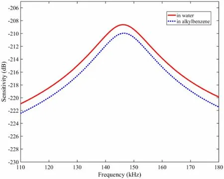
Fig. 6 RVS curves in water and in linear alkylbenzene-based liquid scintillator (obtained from FEM)

where J1is the first-order Bessel function, k, ρ, and c represent the wavenumber, density, and sound velocity in water,respectively.a is the radius of the radiating face,u is the velocity of radiating face, r is the given distance in the far field, and θ is the angle relative to the axis perpendicular to the radiating face.
Assuming that the velocities of the radiating faces are the same, the transmission loss theoretically produces a deviation of 1.361 dB in the far field owing to the difference in the acoustic medium. This value is consistent with 1.34 dB of FEM.
Moreover, the finite element simulations reveal that the piezoelectric stack formed by several thin PCRs pieces in series provides a higher sensitivity than that formed in parallel when the length of Lpis unchanged. This is because of the higher clamped electrical impedance of the former configuration of PCRs.
2.5 Directivity
As shown in the FEM results in Fig. 4,the radiating face of the designed UTH is a circular piston. This produces a regularly distributed acoustic field in the far field [26].For a circular radiating face,the far-field directivity function is given as
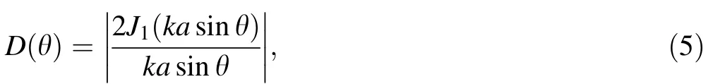
which has a 3 dB down beamwidth,
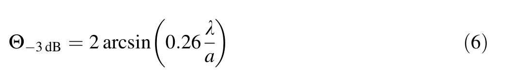
where λ is the wavelength.
As can be seen in Eq. 5, D(θ) is azimuthally symmetric and is only related to θ. According to the reciprocity principles of a transducer, its directivity can be described by transmitting or receiving an acoustic response [27].Figure 7 shows the radiating acoustic field produced by the UTH at a frequency of 145.25 kHz with FEM.The central blank region matches UTH with housing (as shown in Fig. 2). Vibration loads were only applied to the piston radiating face in the simulation. The maximum acoustic response occurs on the acoustic axis,and the acoustic field distribution indicates that most of the energy is transmitted in the forward direction; therefore,UTH is not sensitive to the acoustic wave from the tail direction. The normalized directivity curves at 145.25 kHz are presented in Fig. 8 for the water and liquid scintillators, where 0 dB refers to the acoustic response at the far end of the acoustic axis in water. The curves indicate that the beamwidth was 130.3° in water and 127.5° in the liquid scintillator. The deviation of the maximum acoustic response was 1.81 dB.This deviation is slightly greater than 1.34 dB in Fig. 6,which is mainly attributed to the nickel housing considered in the acoustic field simulation (Fig. 9).
3 Performance tests and results discussions
According to the design, a few prototypes of the UTH(Fig. 9) were manufactured and tested. The detailed configuration, sizes, and materials of the UTH are shown in Fig. 2 and Table 1. The weight of each UTH is 2.50 g.After encapsulation in a nickel housing, its maximum diameter was 22 mm, length was 65 mm, and the weight was ~131 g.
3.1 Radioactivity test
To receive direct ultrasonic signals from the deployed source, eight UTHs were installed on the inner surface of the acrylic sphere (Fig. 1). Radioactivity control is critical inside the CD[28].Material selection is the most effective way of controlling radioactivity levels in UTHs. However,it is difficult to find appropriate materials with low radioactivity, especially for PCR, which, as a core component of UTH, should satisfy both low radioactivity and high electroacoustic transduction. Most piezoelectric ceramics are made of lead zirconate titanate (PZT). In our study, six different varieties of PZT materials were assayed, with levels of238U/232Th ranging from a few to tens of mBq/g. A PZT-4 PCR with a diameter of 8 mm,thickness of 3 mm, and hole of 3.5 mm was chosen to construct the UTHs.
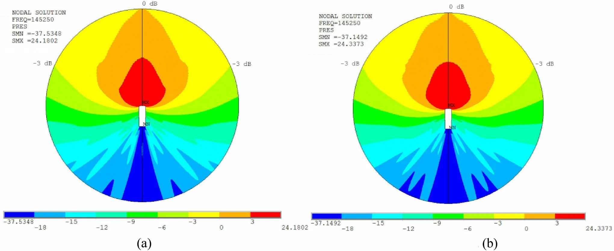
Fig.7 (Color online)Acoustic field produced by the UTH at 145.25 kHz(obtained from FEM).a in water.b in linear alkylbenzene-based liquid scintillator
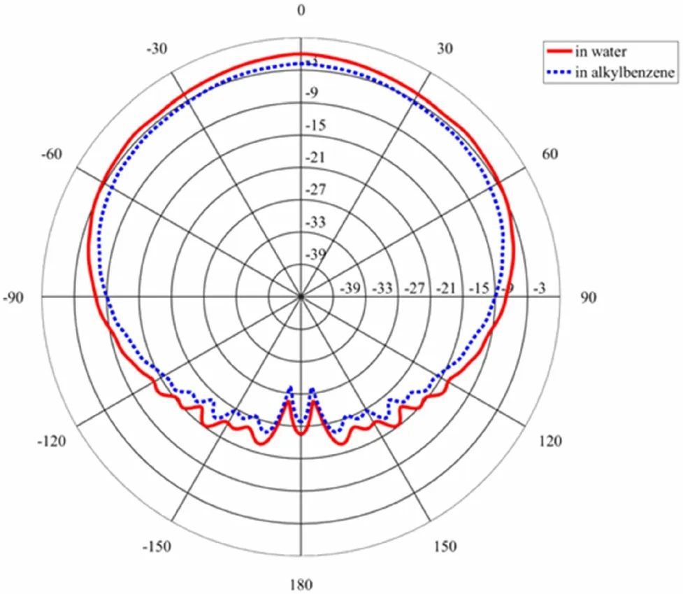
Fig. 8 (Color online) Directivity curves at the frequency of 145.25 kHz in water and in linear alkylbenzene-based liquid scintillator (obtained from FEM)
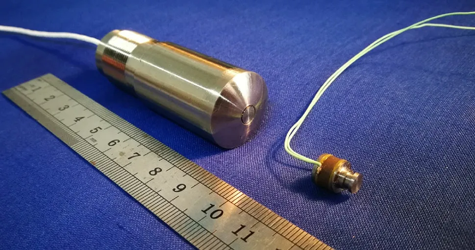
Fig. 9 (Color online) A picture of the full assembly of an UTH
The materials of other parts of the UTH are specially selected to achieve low radioactivity, for example, the radiating head, tail mass, and prestressed bolt were machined from stainless steel, the housing was made from pure nickel, the acoustical insulator was formed by polyurethane, and the sealing material in the housing is epoxy resin. The radioactivity of these materials is negligible compared with that of PCR.
The radioactivity of UTH was measured using a highpurity germanium detector [29], and the calibrated energy distribution of one of the PCRs is shown in Fig. 10. The results of the UTH and its parts are summarized in Table 2,with the dimensions shown in Table 1. The background from a complete assembly,including a coaxial cable with a length of 10 m, is also listed in Table 2, confirming good impurity control during fabrication. Based on these measurements, eight UTHs in the JUNO detector will contribute to a 26 ± 4 mHz trigger rate (0.3 MeV threshold)in the fiducial volume, which meets the 50-mHz requirement of JUNO experiments.

Fig. 10 (Color online) Calibrated energy distribution of one of the PCRs

Table 2 The radioactivity results with upper limits[30]at 90%C.L.of main components of our UTH.The statistic uncertainties are included only 6%systematic error is assigned to the JP-I detector
3.2 Material compatibility test
The UTHs are immersed in the liquid scintillator throughout the lifetime of the JUNO. To detect potential adverse effects on the optical properties of the liquid scintillator, the UTH product was immersed in a liquid scintillator with a glass container in an oven for two weeks.To accelerate the aging, a temperature of 40 °C was maintained. The absorption spectrum of the liquid scintillator was measured before and after immersion, and it was compared with that of a blank liquid scintillator sample,as shown in Fig. 11. The degradation in light absorption at a 430-nm in 20 years, after correcting the surface-to-volume ratios between the test and JUNO conditions,is expected to be less than 10-4.
3.3 Pressure and cleaning test
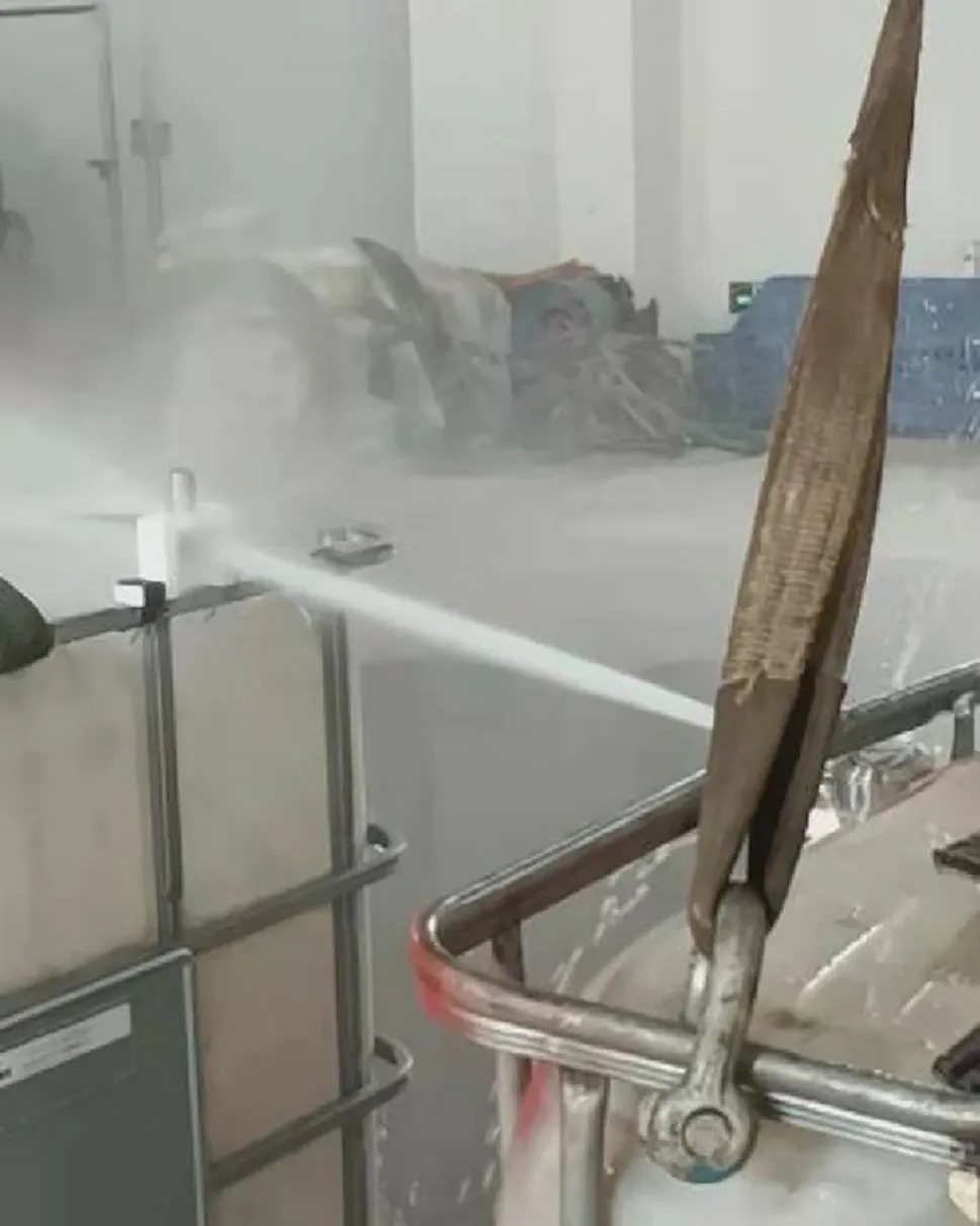
Fig.12 (Color online)The UTH sprayed by a squirt with a strength of 13 atm
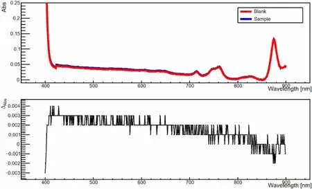
Fig. 11 The absorption spectrum of the liquid scintillator after immersion for two weeks. The red dotted line is from the blank sample and the blue dotted line from the immersion sample.‘‘Abs’’in the Y-axis represents the absorbance value lg(I0/I1) with a 10-cm quartz cuvette,I0 and I1 correspond to the incident light intensity and the transmitted light intensity, respectively. ΔAbs is the difference of‘‘Abs’’ between the sample and the blank

Fig.13 (Color online) Admittance curves in water and in liquid scintillator. (Measured by Agilent 4294A)

Fig. 14 (Color online) Tested RVS curves in water
Most UTHs will be installed at a depth of 26 m under a liquid scintillator in JUNO at a 2.2 atmospheric pressure[8]. In addition, high-pressure water jet (13 atm at the water outlet) spraying during acrylic sphere cleaning may also cause damage to the UTH. To test this, liquid scintillator immersion tests were repeated at 40 °C with the chamber pressurized by a static pressure of 3 atm for two weeks. The UTH was also washed by a squirt with a strength of 13 atm and repeated 10 times for more than 5 s each time (Fig. 12). No change was observed in the electroacoustic performance of the UTH after the tests.
3.4 Electroacoustic test
The electroacoustic performance of the UTH can be assessed based on its admittance,RVS,and directivity.The admittance of the UTH was obtained using a precision impedance analyzer (Agilent 4294A).Figure 13 shows the conductance and susceptance curves of the UTH in water and in liquid scintillator, respectively. The peak of the tested conductance indicates that the maximum G in water is 174.0 μS @142.9 kHz, and that it is 191.9 μS@143.6 kHz in the liquid scintillator.These results were in agreement with the FEM results.Because the characteristic impedance of the liquid scintillator is lower than that of water,the resonance frequency and maximum conductance are slightly higher.
The RVS curves of the UTHs measured in an anechoic tank are shown in Fig. 14, indicating a maximum of -209.3 dB@143 kHz in water. The results are summarized in Table 3, which indicates that the FEM provides a good prediction of sensitivity.Based on these measurements,we estimated that the sensitivity of UTH in the linear alkylbenzene-based liquid scintillator should be approximately - 209.3 dB.
The normalized directivity curve at 143 kHz was also measured in water, as shown in Fig. 15. The curves indicate that the tested beamwidth was 132.2°, which is consistent with the FEM prediction. This confirms that our proposed UTH has a broad beamwidth,but it is not greater than 180°,significantly reducing the impact of the reflected waves.
4 Conclusion
In this study, a special type of UTH was designed and fabricated to serve as the positioning system of the calibration source in JUNO. After careful material selection,the radioactivity level of eight UTHs in the JUNO detector contributes a background of 26 ± 4 mHz, which is less than the requirement of 50 mHz. A finite element model was developed to optimize the electroacoustic performance. With a 33-mode longitudinal vibrating PCR, a maximum RVS in water was-209.3 dB@143 kHz.With a Tonpilz-type circular piston radiating face, the beamwidth can reach 132.2°at 143 kHz in water, which is in goodagreement with the FEM simulation results that were obtained. Such a UTH can satisfy the stringent radioactivity and electroacoustic requirements of JUNO.

Table 3 Electroacoustic performances of UTH(comparison of results between FEM and realistic measurement)

Fig.15 (Color online)Directivity curves,measured and simulated by FEM in water at a frequency of 143 kHz
Author contributions All authors contributed to the study conception and design.Conceptualization were performed by Duo Teng and Jiang-Lai Liu, methodology were performed by Duo Teng and Yue Meng, software were performed by Duo Teng and Jia-Qi Hui,validation were performed by Duo Teng and Jiang-Lai Liu, formal analysis were performed by Duo Teng and Jia-Qi Hui, investigation were performed by Guo-Lei Zhu and Tao Zhang, resources were performed by Kai Luo and Jiang-Lai Liu, data curation were performed by Duo Teng, Yue Meng and Rui Li, visualization and supervision were performed by Kai Luo, project administration and funding acquisition were performed by Guo-Lei Zhu. The first draft of the manuscript was written by Duo Teng, Guo-Lei Zhu and all authors commented on previous versions of the manuscript. All authors read and approved the final manuscript.
杂志排行

Nuclear Science and Techniques的其它文章
- The role of deformations and orientations in an alpha ternary fission of Thorium
- Feedforward compensation of the insertion devices effects in the SSRF storage ring
- A new radar stealth design excited by 210Po and 242Cm
- Development of an ultrafast detector and demonstration of its oscillographic application
- Study on analytical noise propagation in convolutional neural network methods used in computed tomography imaging
- Monte Carlo simulation of neutron sensitivity of microfission chamber in neutron flux measurement