Feedforward compensation of the insertion devices effects in the SSRF storage ring
2022-07-26XinZhongLiuShunQiangTianXuWuMengWangZhenTangZhaoBoYuanFeng
Xin-Zhong Liu• Shun-Qiang Tian• Xu Wu• Meng Wang •Zhen-Tang Zhao • Bo-Yuan Feng
Abstract The lattice of the Shanghai Synchrotron Radiation Facility (SSRF) storage ring was upgraded in the Phase-II beamline project, and thus far, 18 insertion devices (IDs) have been installed. The IDs cause closed-orbit distortions,tune drift,and coupling distortions in the SSRF storage ring,all of which are significant issues that require solutions. In this study, an ID orbit feedforward compensation system based on a response matrix using corrector coils was developed, and it was applied to all commissioned IDs in the SSRF storage ring. After correction, the maximum ID-induced horizontal and vertical orbit distortions were less than 5.0 and 3.5 μm, respectively. Some interesting phenomena observed during the measurement process were explained.Additionally,optical and coupling feedforward systems were developed using quadrupole and skew quadrupole magnets installed on the front and back of elliptically polarizing undulators (EPUs). Moreover, over nearly four months of operation, the developed strategy delivered a satisfactory performance in the SSRF storage ring.
Keywords Shanghai Synchrotron Radiation Facility(SSRF) ∙Insertion devices (IDs) ∙Closed-orbit distortion ∙Tune shift ∙Coupling ∙Feedforward
1 Introduction
The Shanghai Synchrotron Radiation Facility (SSRF) is the first third-generation intermediate-energy synchrotron light source constructed on the Chinese mainland [1] and consists of a 150 MeV linac, a 150–3.5 GeV booster, a low-energy beam transport line, a high-energy beam transport line, and a 3.5 GeV electron storage ring. Since 2009, it has provided a good platform for innovative experiments, contributing to significant advancements in molecular/atomic materials science, chemistry, and biology. As of December 30, 2020, the SSRF had opened 16 beamlines and 20 experimental stations to users, serving 65,651 experimental users during 456,432 h of operation.To increase the number of beamlines and the quality of the light source, some improvements have been made to the upgraded SSRF[2,3].The SSRF Phase-II beamline project was launched in 2015[4].As part of this project,the lattice of the SSRF storage ring was redesigned[5–7],and several complex insertion devices (IDs) have been installed,including in-vacuum undulators (IVUs) [8, 9], cryogenic permanent magnet undulators (CPMUs) [10], elliptic polarized undulators (EPUs) [11], and double elliptically polarized undulators (DEPUs).
Theoretically,the magnetic field integrals of an electron passing through an ID should be zero, because the IDs consist of periodic bending magnets. However, it is difficult for the total field integral to be zero, owing to minor misalignments during the fabrication and installation of an ID. The angle shifts from the first-order magnetic field integral error, and offsets from the second-order magnetic field integral error cause closed-orbit distortions. The quadrupole field and skew quad-rupole field integral errors cause other issues, such as tune drift and beam size changes, impacting the stability of the SSRF operation. During the magnetic design and optimization stage, efforts to minimize the magnetic field integral errors were made. In the SSRF, the first and second magnetic field integral IDs must be lower than 50 and 25,000 G∙cm2, respectively.However, during the user experiment, the gap size and phase shifts of the ID change,resulting in an increase in the first and second magnetic field integral errors.
Slow-orbit feedback (SOFB) [12] and fast-orbit feedback (FOFB) [13] systems attempt to stabilize the closed orbit in the SSRF storage ring. However, the working frequency of slow orbit feedback (SOFB) is 10-1Hz,which is insufficient to correct ID-induced closed-orbit distortions. Furthermore, the correction capability of the FOFB is weak when the ID gap size is changed.Therefore,an IDs orbit feedforward compensation system was required. ID magnetic field integral errors have been studied in various laboratories worldwide, including diamond[14],MAX IV[15],and HEPS[16,17].These errors were also analyzed and compensated for while the IDs were designed in the SSRF. IDs orbit feedforward correctors are used during the SSRF operation. However, the optimal current for each corrector coil is determined by scanning the current of the feedforward coil, which is a time-consuming process even with only four variables[18, 19]. The SSRF Phase-II beamline project has added numerous new complex IDs and changed the optical parameters of the storage ring.Therefore,the current of the feedforward coils for the new IDs should be set, and the feedforward settings of the previously commissioned IDs should be invalid and reconfigured. If a traditional method is used, this process requires considerable machine time.
In this study, a quick-ID orbit feedforward compensation system based on a response matrix using corrector coils was developed.Following feedforward compensation,the maximum ID-induced orbital distortions were less than 5 and 3.5 μm in the horizontal and vertical planes,respectively. Furthermore, this method reduces the time required for measuring the feedforward compensation table by approximately 90%, thereby saving a substantial amount of machine study time. To evaluate the effectiveness of the feedforward system, all commissioned IDs on the SSRF storage ring were evaluated using a feedback system. This method can provide a reference for other light-source operations, particularly fourth-generation diffraction limit storage rings, which require a higher beam orbital stability [20]. Additionally, optics and coupling feedforward compensation were performed using five quadrupole and three skew quadrupole magnets on both ends of the EPUs, which significantly distorted the beam optics and coupling.
The remainder of this paper is organized as follows.Section 1 describes the upgraded lattice of an SSRF storage ring. Section 2 discusses ID-induced closed-orbit distortions, and a quick-orbit feedforward compensation system. Section 3 presents the results of EPU-induced optical distortions,which were compared with and without feedforward compensation. Section 4 describes the EPUinduced transverse beam-size distortions before and after feedforward compensation. Finally, Sect. 5 presents the conclusions of this study.
2 Lattice of the old and new SSRF storage ring
The lattice of the SSRF in the SSRF Phase-I beamline project was designed with 20 double-bend achromat(DBA)cells arranged in four super-periods,16 6.5 m-long straight sections, and four 12 m-long straight sections, with a circumference of 432 m.Each DBA cell had two dipoles,ten quadrupoles, and seven sextupoles with auxiliary coils to produce a skew quadrupole field. Two of the 12 m-long straight sections were used for the installation of the injection system and superconducting RF cavities, respectively, and the remaining 18 straight sections served as beamline stations. Here, 140 beam position monitors(BPMs) were used to perform tune-by-tune orbit measurements,and 80 correctors were used for orbit correction in the SSRF storage ring [21].
The lattice of the SSRF storage ring was upgraded in the SSRF phase II beamline project [22]. The following changes were made to the lattice: 1)Four super-bends with a working field of 2.29 T were installed in the 3rd and 13th DBA cells,adding two more 1.9 m-long straight sections to the SSRF storage ring [3]; 2) double-mini-βyoptics were designed in two other 12 m-long straight sections[4];3)A superconducting wiggler with a peak magnetic field of 4.5 T that emitted hard X-rays was placed between the 11th and 12th DBA cells [5]. The current linear optical functions and magnetic layout of the SSRF storage ring are shown in Fig. 1. The primary parameters of the old and new SSRF storage rings are listed in Table 1. The natural emittance, energy spread, and energy loss per turn of the new SSRF lattice are higher than those of the old SSRFlattice. The betatron tunes of the new SSRF lattice are charged to 22.222 and 12.153 in the horizontal and vertical planes, respectively.
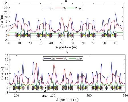
Fig. 1 (Color online) Linear optical functions and magnet layout of the new SSRF storage ring. a: A super-period with a super-bend and b: double-miniβy and SCW
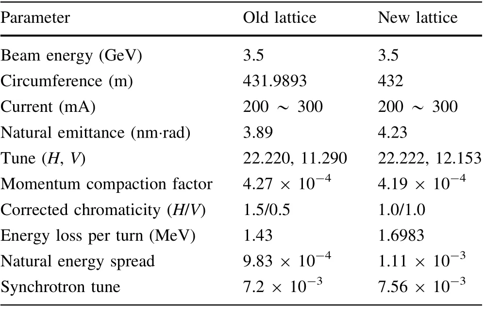
Table 1 Main lattice parameters of the old and the new SSRF storage rings.
In addition to the upgraded SSRF lattice, the SSRF storage ring currently has 18 IDs that have been completely installed and are operational, including nine IVUs, one wiggler, three CMPUs, and six EPUs. The magnetic field strength of the IVUs can be changed by altering the gap size. The minimum gap between all IVUs in the SSRF storage ring is 6 mm. CMPUs can produce a higher magnetic field than that produced by room-temperature undulators.The EPUs have four movable magnets that can be adjusted in terms of the gap size and phase shift.Varying the gap size changes the field intensity, which subsequently changes the energy of the emitted photons.A change in the phase shift alters the periodicity of the field,which changes the helical trajectory of the electrons,thereby controlling the polarization of the emitted photons.Units 07 and 09 were equipped with two EPUs(07EPU58,07EPU90, 09EPU58, and 09EPU148). The users of beamline stations 07 and 09 can choose any one EPU based on the experimental requirements, thus enhancing the scope for innovative experiments and significantly improving station utilization efficiency.
3 Closed-orbit distortions
3.1 Method of IDs feedforward compensations
To correct the ID-induced closed-orbit distortions, a two-point impact model was adopted, the impact points were selected at the inlet and outlet of the ID, and four correction coils were installed for each ID to compensate for the horizontal and vertical orbit closed-orbit distortions simultaneously. The orbit response matrix and singular value decomposition (SVD) [23, 24] were used in the feedforward compensation of the IDs. Here, A represents the horizontal and vertical orbits of 140 BPMs, each of which has four correction coils, and any element in A can be described by four variables (each representing a compensation current of the corrector coils), as illustrated below.

where Aiis the closed-orbit distortion at the position of the BPMi, and Iiis the current in the corrector coils. Because the beam oscillation phase between the feedforward corrector coils and IDs is negligible,the closed-orbit distortion caused by an ID field integral error of 140 (BPMs) can be reduced using only two feedforward variables. In addition,a gradient descent method can be used to optimize the current of the feedforward coil because the closed-orbit distortions with respect to the compensation current are relatively linear. The response matrix for each I in A is a Jacobian matrix consisting of the following elements:
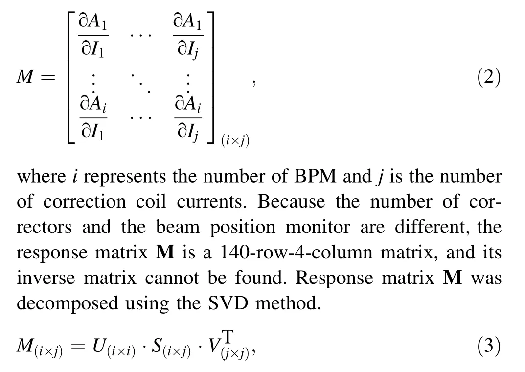
S(i×j)is a singular value matrix in which all elements except the diagonal elements (singular values) are zero.

where Inewis the required current of the feedforward coil of the ID and Iinitis the initial current of the corrector coil.According to Eq. (6), after only one or a few iterations, a satisfactory current for the feedforward coil can be obtained using this algorithm.
3.2 Orbit feedforward compensations for planar IDs
During the operation of user time, the gap size of the planar ID is varied based on the experimental requirements of the user. To ensure that the orbit distortions at all gaps were suppressed, we developed a feedforward correction program based on a response matrix. Twenty-five gaps were set between the maximum and minimum gaps of the planar IDs. Approximately 15 min were required to measure the feedforward coil currents for a planar ID. The duration of this method is primarily determined by the response speed of the corrector coils and rate at which the ID gap can be changed. This considerably decreases the machine-study time, as it takes approximately one-tenth the time of the previous two-dimensional (2D) scanning method. Table 2 lists the commissioned planar ID-induced closed-orbit distortions before and after the application of the feedforward compensation. The D10 straight is a typical 6.5 m-long straight section in the SSRF storage ring and hosts two in-vacuum undulators, 10IVU1 (Time-Resolved USAXS Beamline) and 10IVU2 (Biosafety P2 Protein Crystallography Beamline),providing X-rays in the 5–20 keV energy range.Taking the planar IDs 10IVU1 and 10IVU2 as examples,the closed-orbit distortions versus the gap sizes of 10IVU1 and 10IVU2 before and after the application of feedforward compensation are shown in Fig. 2a and b, respectively. The compensation current of the corrector coils versus the gap is shown in Fig. 2c and d.
As listed in Table 2, four IVUs and a wiggler were installed in the SSRF phase I beamline project. After applying the old feedforward compensation (O-FF), the IVUs and wiggler caused maximum orbit distortions of 31 and 21 μm in the horizontal and vertical directions,respectively, demonstrating that the O-FF was not useful for orbit feedforward compensation. Five IVUs and three CPMUs (02CPMU, 16CPMU, and 17CPMU) were installed in the SSRF phase II beamline project. Before application of the new feedforward compensation, the IVUs caused orbit distortions of 30 and 20 μm in the horizontal and vertical directions,respectively;02CPMU caused even larger distortions of 90 and 55 μm, respectively. Orbit distortions with such high magnitudes would have a significant impact on user experiments. However, after the application of feedforward compensation, the maximum orbit distortions caused by the IVU and CPMU were less than 2.5 and 5 μm, respectively. Therefore, our feedforward compensation scheme adequately compensated for the orbit distortions of the planar IDs for the experimental requirements of SSRF users.As shown in Fig. 2a and b,the maximum root-mean-square values of the closed-orbit distortions caused by the changes in gaps of 10IVU1 and 10IVU2 were less than 2 μm. Figure 2c and d shows that the current of the feedforward coil changes smoothly with respect to the gap size, which is highly beneficial in practice because it allows the current of the feedforward coil to be adjusted to accommodate any ID gap. This also ensures that gap adjustments at the beamline station do not significantly affect the users at other beamline stations.

Table 2 Planar ID-induced horizontal and vertical closedorbit distortions (CODs) before and after the application of ID feedforward compensation.
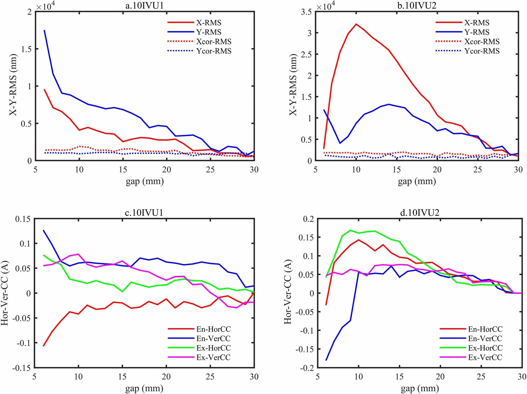
Fig.2 (Color online)a and b:Closed-orbit distortions of 10IVU1 and 10IVU2 versus the gap size(The results obtained before and after the feedforward compensation are represented by solid and dotted lines,respectively.); c and d: Horizontal and vertical compensation current of corrector coils versus the gap size. (En-HorCC and En-VerCC represent the horizontal and vertical compensation current at the entrance of the ID, respectively. Ex-HorCC and En-VerCC represent the horizontal and vertical compensation current at the entrance of the ID, respectively)
3.3 Orbit feedforward compensations for EPU
The gap size and phase shift of the EPU were repeatedly adjusted for scientific experiments at the beamline.Therefore, each feedforward point of an EPU depends on two dimensions (phase shift and gap size).To improve the efficiency of the process by which the compensation current of the corrector coils was configured,we established a 2D feedforward table with 35 different values in the gap column and 30 different values in the phase-shift column for the EPUs. The gap intervals were small, and closedorbit distortion was particularly sensitive to changes in the gap size. In May 2021, this method was used to configure the current of the feedforward coils of all commissioned EPUs in the SSRF storage ring. Four 2D feedforward tables must be measured for 07DEPU because their magnetic blocks should phase-shift in the same and opposite directions. Because 20EPU60 has five operating modes, with modes 0 and 4 being fixed-phase shift modes,three 2D feedforward tables and two 1D feedforward tables were measured for this EPU. The duration of this method depends on the moving speed of the ID gap and phase shift. The duration for the measurement of the feedforward compensation current of the corrector coils in one working mode of a single EPU is approximately 4 h,which is estimated to be one-tenth of the time taken by the original scanning mode. The pre-and post-compensation orbit distortions of all the operational EPUs in the SSRF storage are listed in Table 3. Taking 07EPU58 and 07EPU90 (Spatial and Spin Beamline), for example, the same-direction pre-and post-compensation orbit distortions of 07EPU58 and 07EPU90 in the horizontal and vertical directions are shown in Fig. 3a,b,c,and d.The changes in the current of the feedforward coil with the phase shift and gap are shown in Fig. 3e and f.
As listed in Table 3, two DEPUs (07DEPU and 09DEPU) and an EPU (20EPU60) with four modes were installed in the SSRF Phase-II beamline project. The maximum root-mean-squares of the closed-orbit distortions owing to an EPU were 97 and 187 μm in the horizontal and vertical directions, respectively, without feedforward compensation.In addition to having a significant impact on user experiments, orbit distortion with such high magnitudes would cause beam loss. The majority of the closedorbit distortions were reduced to less than 5 μm after using the ID feedforward compensation. The first feedforward compensation was sub-optimal at 09DEPU, with distortions larger than 20 μm owing to considerable errors in the current readout of its feedforward corrector coils. During the SSRF summer shutdown for maintenance studies, the power of the corrector coils was switched from pulse power to digital power. We remade the 09DEPU feedforward table and reduced the 09DEPU-induced closed-orbit distortions to less than 5.0 μm using the new feedforward compensation. Figure 3a, b, c, and d shows that the closed orbit distortion caused by the phase shift change is periodic rather than uniform, and a monotonous variation is caused by the gaps;therefore,the number of points at phase shifts must be sufficient. Overall, our feedforward compensation scheme worked well for EPUs,reducing orbit distortions to acceptable levels for most beam-station users. Furthermore,Fig. 3e and f shows that the changes in the current of the feedforward coils with respect to the gap and shift were very smooth, allowing the use of arbitrary shift and gap values.
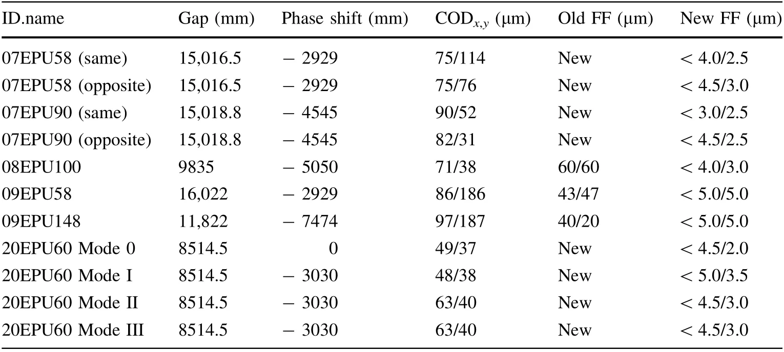
Table 3 EPU-induced horizontal and vertical COD before and after the application of feedforward compensation.

Fig. 3 (Color online) a, b, c and d: Changes in the same-direction orbit distortion with gap size and phase shift before and after feedforward compensation of the 07EPU58 and 07EPU90; e and f:changes in the current of the feedforward coil at four corrector coils with gap size and phase shift
3.4 Discussion of the measurement results
A few phenomena were observed during the course of this study. The relationships between the gap size of a planar ID and its horizontal and vertical orbital distortions without compensation are shown in Fig. 4a and b. The dotted and undotted lines represent the closed-orbit distortions of IDs installed during the SSRF Phase II and Phase I projects, respectively. The closed-orbit distortions of 07EPU58 with changes in the gap size at a few different phase shifts without feedforward compensation are shown in Fig. 4c. Figure 4d corresponds to the changes in the orbit distortion that occur with changes in the gap size of 07EUPU58 (also without feedforward compensation).

Fig. 4 (Color online) a and b: Horizontal and vertical closed-orbit distortions versus the gap size without feedforward compensation.The dotted and undotted lines represent the closed-orbit distortions of IDs that were installed during Phase-II and Phase-I projects,respectively. c: Changes in the closed-orbit distortion with changes in shift.Each color denotes a different gap.d:Changes in the closedorbit distortion with changes in the gap at a few shifts in the 07EPU58 same direction mode; each color denotes a different shift. No feedforward compensation was applied in these measurements
1) Some ID-induced orbit distortions (10IVU2, 15IVU,and 19IVU1) decreased as the gap size of ID decreased at small gap sizes, as shown in Fig. 4a and b. This is consistent with the design of the IDs.2)In the scenario without feedforward compensation,newer IDs caused smaller orbit distortions than older IDs in the horizontal direction. This indicates that the intrinsic field integral errors of the newer IDs are less than those of the older IDs, which could indicate an improvement in ID fabrication. 3) The IDs installed during Phase-II and Phase-I projects caused approximately the same orbit distortions in the vertical direction. This is because a planar ID has no horizontal magnetic field. The first-order and second-order field integral errors in the vertical direction were caused by minor misalignments in the installation.4)Figure 4c shows that when the gap size is fixed,the vertical orbit distortions caused by 07EPU58 vary sinusoidally with changes in the shift. This is consistent with the longitudinal trends of the second-order magnetic field integrals of the EPU. 5) Figure 4d shows that uncompensated closed-orbit distortions increase drastically when the gap is small, which is approximately consistent with the EPU’s field integral errors being positively associated with e-π(g-gmin)/λID(λIDis the period of ID).
4 EPU-induced optical distortions
and feedforward compensation The ID-induced optical distortions were measured.Currently,only 09DEPU(09EPU58 and 09EPU148)in the SSRF storage ring has a severe impact on beam optics,causing tune drift. This reduces the stability of the SSRF operation; thus, new optic feedforward compensation is required. Tune distortions can be calculated as follows:
where Δνx,yis the betatron tune distortion, βx,y(s ) is the beta function at position s,and δK is the change in strength of the quadrupole magnet. According to Eq. 7, the tune distortions can be corrected using the quadrupole magnets.In this study, five quadrupole magnets on the front and back of the EPU were used to compensate for changes in the tune [25]. Linear optics from the closed orbit (LOCO)software developed by Safranek et al. [26] was used to perform beam optics corrections. Initially, the response matrix of the tunes to each corresponding quadrupole magnet current was measured. The tune shifts induced by 09EPU58 with different gap sizes were measured for various phase shifts as the machine physics were being studied. The measured results revealed that the effects of changes in the longitudinal position of the EPU on the tunes were negligible. Therefore, to perform optical feedforward compensation, the optical feedforward tables need only comprise the corresponding quadrupole magnet currents with different gap sizes.The changes in the tunes due to changes in the gap size before and after optic feedforward compensation are shown in Fig. 5.
As shown in Fig. 5, before applying the feedforward compensation, as the gap size of 09EPU58 decreases, the horizontal tune decreases and the vertical tune increases;furthermore, the changes in the gap size have a significant impact on the tunes when the gap is less than 80 mm.When the gap size was adjusted from 160 to 18 mm, the maximum tune shifts caused by 09EPU58 were 0.007 and 0.014 in the horizontal and vertical directions,respectively.After the application of the feedforward compensation, the maximum tune shift caused by 09EPU58 was less than 0.002 in both the horizontal and vertical planes. Thus, the feedforward compensation scheme was effective and adequately compensated for the optical distortions.
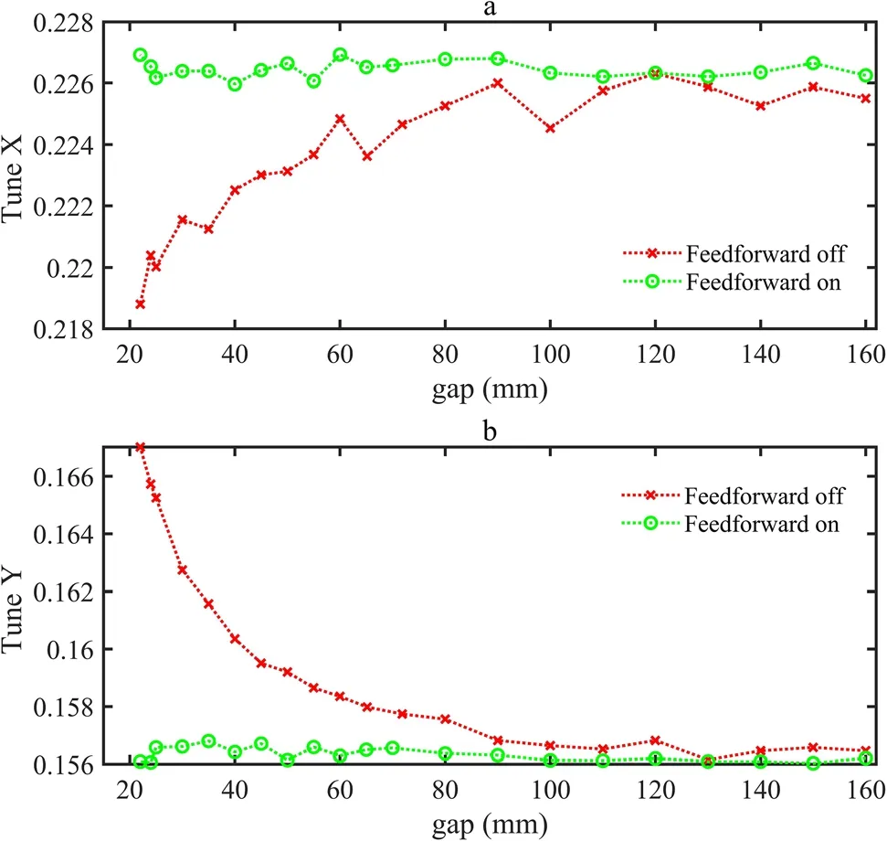
Fig. 5 (Color online) Tunes as a function of the gap size before and after feedforward compensation
5 EPU-induced coupling distortions and feedforward compensation
While studying the beamline, we observed that the effects of planar IDs and most of the EPUs on beam coupling were negligible in the SSRF storage ring. However,09DEPU had a significant impact on the coupling parameters, and the beam size increased by 30%, which reduced the brightness of the synchrotron radiation and increased the data collection time of the SSRF users.
To address this problem, coupling feedforward compensation was performed using three skew quadrupole magnets on both ends of the EPUs. The response matrix can also be used to measure and correct the ID-induced beam size distortions.The skew quadrupole magnetic field intensities are required to correct these distortions by analyzing the coupling terms of the response matrix[27, 19]. First, the coupling distortions induced by 09EPU58 with different phase shifts are measured. The location of the beam size measurement was at the light outlet of the first dipole magnet in Unit 1. The measurement results also reveal that longitudinal variations in the EPU position have only a small effect on the beam spot size (approximately 5%). Therefore, the effects of the phase shift are negligible, and it is necessary to consider only the size of the gap when performing coupling corrections. Figure 6 shows the changes in the horizontal(a)and vertical(b)beam sizes with changes in the gap size before and after feedforward compensation.
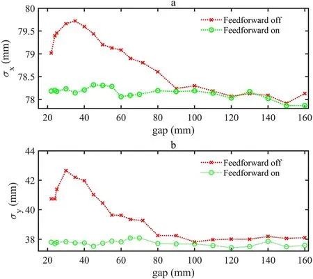
Fig. 6 (Color onine) Changes in the horizontal (a) and vertical(b) beam size verses the gap of 09EPU58 before and after feedforward compensation
As shown in Fig. 6, when the gap size is approximately 32 mm, the beam size reaches a maximum, that is, 80 and 42.9 mm for the horizontal and vertical axes, respectively,which are approximately 2.5%and 13.0%larger than those corresponding to the maximum gap. The brilliance of synchrotron radiation is inversely proportional to the beam size. A considerable change in the beam size will have a non-negligible impact on user experiments of the beamlines, especially for scientific experiments that are sensitive to light flux. Following compensation, the maximum change in the beam size due to a change in the gap was 0.5 mm or less. Although changes in beam size still exist when the gap of 09EPU58 is changed,these are very small compared to those before feedforward compensation,which is satisfactory for user experiments. Hence, our feedforward scheme was successful in stabilizing the beam size and the brilliance of the SSRF.
6 Conclusion
In this study, a quick orbit feedforward compensation system was established and applied to all the existing IDs in the SSRF storage ring. This method reduces the time required for feedforward compensation by approximately 90%,thereby saving a substantial amount of machine study time.In addition,after orbit feedforward compensation,the maximum ID-induced horizontal and vertical orbit distortions were less than 5.0 and 3.5 μm, respectively. The changes in the current of the feedforward coil with respect to the gap and phase shift were smooth,which is beneficial for the implementation of feedforward compensation in practical settings.The EPU-induced tune drift and coupling distortions were corrected using quadrupole and skewed quadrupole magnets at both ends of the EPUs.After optical and coupling feedforward compensation, the EPU-induced tune drift was observed to be less than 0.002,and the EPUinduced distortions of the beam size were less than 0.5 mm. These feedforward systems are effective at compensating for the effects of IDs on the SSRF storage ring,which is critical for the experimental requirements of SSRF users.
AcknowledgementsThe authors would like to thank Dr.Wei Zhang and He-Yun Wang for their useful discussions and the machine setup.
Author contributions All the authors contributed to the conception and design of the study. Material preparation, data collection and analysis were performed by Xin-Zhong Liu, Shun-Qiang Tian, Xu Wu, Meng Wang and Zhen-Tang Zhao. The first draft of the manuscript was written by Xin-Zhong Liu, and all authors commented on the previous versions of the manuscript. All authors have read and approved the final manuscript.
杂志排行

Nuclear Science and Techniques的其它文章
- The role of deformations and orientations in an alpha ternary fission of Thorium
- A new radar stealth design excited by 210Po and 242Cm
- Development of an ultrafast detector and demonstration of its oscillographic application
- Low-radioactivity ultrasonic hydrophone used in positioning system for Jiangmen Underground Neutrino Observatory
- Study on analytical noise propagation in convolutional neural network methods used in computed tomography imaging
- Monte Carlo simulation of neutron sensitivity of microfission chamber in neutron flux measurement