A new radar stealth design excited by 210Po and 242Cm
2022-07-26JinJianYuanGuiPingMengMinGuRunShengHuang
Jin-Jian Yuan• Gui-Ping Meng • Min Gu • Run-Sheng Huang
Abstract Open plasma stealth technology excited by radionuclides is known to have several problems:(1)owing to disturbance from airflow, the plasma distribution is unstable. (2) The plasma is highly dependent on the atmosphere; therefore, it is difficult to modulate in target stealth. (3) Concerns regarding radiation harassment prevent the application of this method. To avoid these problems,an enclosed plasma stealth method is introduced.Via simulation on an infinite conducting plate,this method was found to effectively solve the above concerns, which may offer a new approach for the practical application of plasma stealth technology excited by radionuclides, especially for small-satellite stealth because of its lightweight and selfprovided plasma.
Keywords Radiation ionization ∙α Decay particles ∙Plasma film ∙Radar stealth technology
1 Introduction
Modern detection and guidance technologies have been rapidly developed and widely applied, which poses a great challenge for the survivability of aeronautical weapons,such as aircraft and missiles, on the battlefield. To reduce the observability of targets,stealth technology is employed.Radar stealth technology is mainly designed to obstruct radar detection and identification by reducing the radar cross section. The recent development of plasma stealth technology, a new radar-characteristic control technology,has attracted significant attention because of its wide absorbed frequency band and attenuation. Recent studies have focused on the generation of plasma and the influence on electromagnetic waves (EMWs) from plasma with different parameters. The latter has been studied in detail[1–6], yet the former has not. Plasma generators in stealth technology have been tested in gas discharge, shock wave plasma, miniature solid rocket engine tail flames, and radionuclides [7, 8].
The idea of using radionuclides to generate plasma was first reported in the 1970s; it was revealed that a reflected radar wave can be attenuated at 70 dB when a copper plate is coated with a certain radioactivity of210Po [8]. A detailed study on the radar stealth of targets with various shapes coated with radioactive materials (210Po,238Pu,241Am,and242Cm) has been conducted,which showed the good stealth performance of this method[9,10].However,there are several problems in the practical application of open plasma stealth technology excited by radionuclides.First, plasma distribution is greatly disturbed by airflow,which means high robustness is required to ensure stable stealth performance.Second,the thickness,collision frequency, and electron density of plasma are highly atmosphere dependent; hence, it is difficult to modulate.Third, concerns around radiation harassment prevent the practical use of this method. To avoid these problems, an enclosed plasma stealth technology excited by radionuclides is suggested.A detailed simulation revealed that this method can solve the above problems and ensure stealth performance. Furthermore, with the development of small near-earth satellites in recent years, their radar stealth has received more attention because the weight of traditional coated radar stealth equipment cannot be ignored for small satellites, and traditional plasma stealth technology cannot be used in outer space. However, the plasma stealth technology introduced in this paper would be suitable for this purpose owing to the self-provided plasma and extremely light weight.
2 Design program
A schematic of the enclosed plasma stealth technology generated using radionuclides is shown in Fig. 1a.The film was constructed using gas-encapsulated melamineformaldehyde resin (MF) microsphere shells and radioactive materials glued with flexible resin,and the plasma was generated in the ionization of encapsulated gas by the emitted α particles. The target was stealthy when the surface was coated with the film. For convenience, a single sheet of MF microsphere shells will be referred to as an MF layer (MFL), a single-layer film composed of MFLs and radioactive material as a single plasma film(SPF),and film composed of multiple SPFs as plasma film(PF).Moreover,because the size of MF microsphere shells is significantly smaller than the radar wavelength, the radiation is homogeneous and isotropic, and therefore, the PF shown in Fig. 1a can be simplified to a multilayer structure, as shown in Fig. 1b.
The relative permittivity of plasma is given as [4, 11]
where ω0is the incident wave frequency,ωP is the plasma frequency, and ν is the effective collision frequency of electrons.

Fig. 1 (Color online) Schematic of the enclosed plasma film. a Real model; b simplified model

where neis the electron density in m-3, e is the electron charge, meis the electron mass, and ∊0is the vacuum permittivity.Therefore,the plasma frequency only depends on electron density.
2.1 Plasma excited by radionuclides
Electron density is determined using the transport equation.The electron diffusion in plasma is similar to the free diffusion of gas molecules [13].

Table 1 Parameters of the used gases[14–16]

where α is the recombination coefficient given by α=2∙7×10-13/(kBTP)3/4cm3s-1[9, 19], and the unit of kBTPis eV.
Because negative ions produced at the electron attachment are not stable[9, 10, 13], the process of electrons attached by neutral molecules (La) can be ignored here.
Substituting G(r→,t) and Lr into Eq. 4,

Solving Eq.7,we can obtain the steady-state distribution of the electron density in the MF microsphere shell. The parameters affecting electron density include the atmospheric temperature,encapsulated gas type,pressure in the shell, α particle energy, PAR of the radioactive material,and position of the spherical shell relative to the radioactive material.
2.2 Reflection coefficient of electrically large target
When coating the PF on an electrically large target, its interaction with an EMW can be described as a multilayer structure with the EMW, as shown in Fig. 2. The incident layer (on the left) is air, and the target (on the right) is always replaced with a perfect electrical conductor (PEC).From the incident layer to the PEC layer, all layers are numbered from 0 to m+1, where 0 is the incident layer and m+1 is the PEC.When the EMW propagates through the multilayer film, the fields in every layer satisfy the following relations via the transfer matrix method (TMM)[20]:


Fig. 2 Schematic of the propagation of an electromagnetic wave in multilayer film

The parameters that affect the attenuation of the reflected EMW include the atmospheric temperature, encapsulated gas type, pressure in the shells, α particle energy, PAR of the radioactive material,number of SPFs(thickness of PF),and the frequency, incident angle, and polarization of the incident EMW.
3 Simulation results and discussion
3.1 Preventing radiation leakage
To prevent radiation leakage, we analyzed the travel distance (range) of α particles in the PF. Because the thickness of the PF must be increased (decreased) with an increase(decrease)in the number of MFLs,we use‘‘Range Layer’’ to describe the maximum number of MFLs penetrated by α particles, which mainly depends on the α particle energy and PF properties.For example,the properties of one of the constructed MF microsphere shells were as follows: the outer diameter was approximately 50 μm, the wall thickness was approximately 5 μm, the compressive strength was 10 atm, the density was 1.1 g/cm3, and the refractive index was 1.6 [21]. Two pure α decay radionuclides (210Po and242Cm) were considered because their specific activities were 3891.9 Ci/g and 3324.3 Ci/g,respectively. Their relative activities were significantly larger than those of other pure α decay radionuclides. The energy of the α particle emitted by210Po was 5.301 MeV(100%),whereas that by242Cm was 6.069 MeV(26%)and 6.112 MeV(74%). Their Bragg peaks in the MF are given in Fig. 3.The range of the 5.301 MeV α particle was approximately 40 μm,and that of the 6.069 or 6.112 MeV α particle was approximately 50 μm. To obtain the same range in gaseous He, Ne, Ar, or CO2, densities of 1.0 g/cm3,1.55 g/cm3,1.90 g/cm3,and 1.30 g/cm3,respectively,should be set. When the atmospheric temperature was 300 K, according to the state equation, their corresponding pressures were 6150 atm, 1891 atm, 1171 atm, and 727 atm,which are significantly larger than the pressure used in practice. Therefore, the leakage of α particles was mostly prevented by the MF.

Fig. 3 Bragg peaks of α particles within the MF
Although the encapsulated gases barely prevented the leakage of α particles, the different energy losses of the α particles affected the range layer.To obtain specified range layers with different radionuclides and gases at an atmospheric temperature of 300 K,the required pressures in the microsphere shell are listed in Table 2. Among them, the minimum value was also significantly larger than the compressive strength of the MF microsphere shell (10 atm).Therefore,in the PF,the range layer of the α particles emitted by210Po or242Cm was only 4/5 MFLs, respectively. Although the radiation of the radioactive material was isotropic,leakage prevention of the emitted α particles could be realized by sandwiching them in the SPF, as shown in Fig. 1.The thickness of the SPF constructed with210Po or242Cm was only 8/10 MFLs (approximately 0.4/0.5 mm).
3.2 Electron density in the microsphere shell
From the above,it was found that the electron density in the MF microsphere shell was affected by the atmospheric temperature,encapsulated gas type,pressure in the shell,α particle energy, PAR of the radioactive material, and position of the microsphere shell relative to the radioactive material. It appears that no matter how much these parameters changed, the contour lines of the electron density were approximately parallel to the temperature axis and perpendicular to the other, as shown in Fig. 4. Therefore, the electron density was almost independent of atmospheric temperature.
The change in the electron density contours in Fig. 4b indicates that the electron density increased with increasing PAR. By taking the logarithms of the electron density and PAR, a linear correlation was obtained, that is,lg(ne2/ne1)=k ∙lg(A2/A1), as shown in Fig. 5. After fitting, the value of k was approximately 0.5, and the deviation was less than 0.001, whereas other parameters changed.
The relative position of the MF microsphere shell to the radioactive material leads to a change in the electron density in the shell with the pressure in the shell. The electron density in the shells located outside the range layer increased with increasing pressure in the shells, but decreased with increasing speed, as shown in Fig. 4a. At the same shell pressure, the electron densities for different gases,listed from the largest to smallest values,were CO2,Ar, Ne, and He, as shown in Fig. 6a. The electron density in the shells located at the range layer first increased and then decreased with increasing PRSM,as shown in Fig. 6b,which was easily observed when the gas was CO2or Ar yet was almost unobserved when the gas was He or Ne. From Eq. (5), the electron density was proportional to the deposition energy of α particles in the gas.With increasing PRSM, the deposition energy of α particles in Ar or CO2gas increased. However, the deposition energy of α particles in the shells located at the range layer decreased with increasing PRSM when the PRSM was greater than a certain value because most of the energy of the α particles was lost in the MFLs near the radionuclide material.Therefore, the trends of the Ar and CO2curves first rose and then fell. Meanwhile, because the energy loss of the α particles in CO2or Ar was larger than that in He or Ne,this phenomenon was almost unobserved when the gas was one of the latter.
3.3 Radar echo attenuation
According to the above analysis, the reflected EMW attenuation was dependent on the atmospheric temperature,encapsulated gas type, pressure in the shell, α particle energy, PAR of the radioactive material, number of SPFs(thickness of the PF), and the frequency, incident angle,and polarization of the incident EMW.
Open plasma stealth technology is highly atmosphere dependent; however, only atmospheric temperature can affect an enclosed device, as previously analyzed. As shown in Fig. 7, the reflected curves under different atmospheric temperatures almost completely overlapped.This shows that the enclosed plasma stealth technology excited by radionuclides was barely affected by theatmospheric temperature; therefore, it effectively avoided the dependence on atmosphere.
Table 2 Required pressure to obtain specified range layers at TMF =300 K (units: atm)

Fig.4 (Color online)Electron density in the microsphere shell near the radioactive material.The radionuclide is 210Po,the encapsulated gas is CO2, and a the PAR is 1 mCi/cm2; b the PRSM is 1 atm

Fig. 5 Electron density versus PAR while the shells are near the radioactive material, the PRSM is 1 atm, the radionuclide is 210Po, and a the encapsulated gas is CO2; b the PRSM is 1 atm
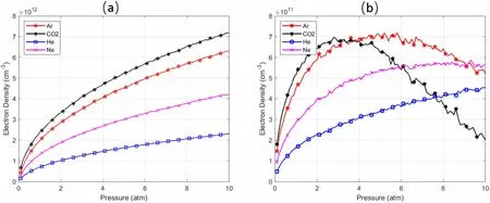
Fig.6 Electron density versus PRSM while the radionuclide is 242Cm,the PAR is 50 mCi/cm2,and the shells are a near the radioactive material;b located at the range layer

Fig. 7 Reflected power versus frequency at different atmospheric temperatures while the radionuclide is 242Cm, the PAR is 50 mCi/cm2, the encapsulated gas is CO2, the PRSM is 3 atm, and the SPF number is 50
For open plasma stealth technology, only air can be considered for the gas;however,we can choose any type of gas to be encapsulated in the enclosed device.Furthermore,we can obtain a similar attenuation with different gases by adjusting only the radioactivity.This means that for stealth performance,the changing of the gas type and the changing of the PAR of the radioactive material are equivalent, and clearly the changing of the PAR is more flexible.If we pick the latter as the control parameter, the choice of gas will only affect the cost of the radioactive material. For example, when the gas is CO2, 16.7%, 64.3%, and 90.7%of242Cm will be saved compared with Ar, Ne, and He,respectively.
When the PAR of the radioactive material was small(such as,5 mCi/cm2),EMW attenuation greater than 10 dB was located in the low-frequency domain, but its bandwidth was narrow(widest is 2.5–4.6 GHz).However,as the PAR increased, the widest bandwidth of EMW attenuation greater than 10 dB will gradually widened, while its upper and lower frequency points moved toward the higher side along the frequency axis. As shown in Fig. 8, when the PAR of the radioactive material was 0.5 Ci/cm2,the widest bandwidth of attenuation over 10 dB was 4.9–283 GHz,which was significantly wider than when the PAR was 5 mCi/cm2; however, the attenuation of the EMWs whose frequencies were below 4.9 GHz was less than 10 dB.
When the PF was thinner (such as 25 SPFs), the EMW attenuation greater than 10 dB was located in the lowfrequency domain, but its bandwidth was narrow (widest was 5.5–10 GHz). Comparing Fig. 9a, b, with increasing PF thickness, the largest bandwidth of EMW attenuation greater than 10 dB gradually increased, while the upper frequency point moved toward the higher side and the lower point moved toward the lower side along the frequency axis. This was different with increasing PAR.
Therefore, we could increase the EMW attenuation in the high-frequency domain via enriching the PAR of the radioactive material or thickening the PF; however, in the low-frequency domain only the latter method could be achieved. Regardless of whether we increase the PAR or thicken the PF, the cost of the radioactive material and adjusted pressure in the shells should be considered. As given in Fig. 10, two different devices with a broad attenuation bandwidth of 2–50 GHz, which covers most common frequencies used in radar, were obtained by modifying the PAR of the radioactive material and the thickness of the PF. The encapsulated gas was CO2. The radioactive materials were 50 mCi/cm2of242Cm and210Po,the thicknesses were 2.5 cm (blue dotted line) and 2.4 cm(black solid line),respectively,and the corresponding areal densities were 0.991 g/cm2and 0.951 g/cm2, respectively.The light weight and self-provided plasma of this method perfectly suit small-satellite radar stealth technology,while near-Earth satellites utilized in wars, such as Musk’s ‘‘Star Chain’’, are currently being used in the Russia–Ukraine conflict.
As we know, the change in the reflected EMW attenuation with incident angle differs as the polarization changes. However, the changing of polarization or incident angle cannot significantly narrow the attenuation bandwidth. For example, as shown in Fig. 11, as the incident angle increased in the range 0–45°and the other condition was the optimized242Cm (blue dotted line in Fig. 10), the maximum attenuation peak of the TE wave increased,whereas that of the TM wave decreased; however, the bandwidth of EMW attenuation greater than 10 dB was almost unchanged. This shows that even for networked radar, this method will provide the target with excellent stealth performance.
4 Conclusion
The stealth performance of open plasma technology excited by radionuclides has been widely verified using theory and experiments.However,its practical applications remain limited owing to the disturbance of plasma distribution from airflow, the dependence of plasma properties on the atmosphere, and concerns regarding radiation harassment. The enclosed plasma stealth technology excited by radionuclides presented in this paper provides a new approach for the application of plasma stealth technology in practice.

Fig. 8 (Color online) Reflected power while the SPF number is 50, the radionuclide is 242Cm, the encapsulated gas is CO2, and the PAR is a 5 mCi/cm2; b 0.5 Ci/cm2
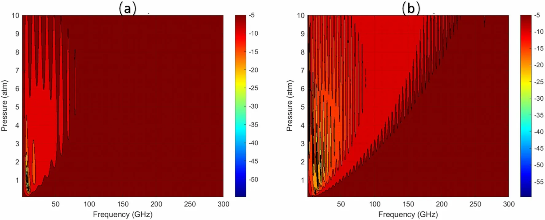
Fig. 9 (Color online) Reflected power while the radionuclide is 242Cm, the encapsulated gas is CO2, the PAR is 50 mCi/cm2, and the SPF number is a 25; b 50
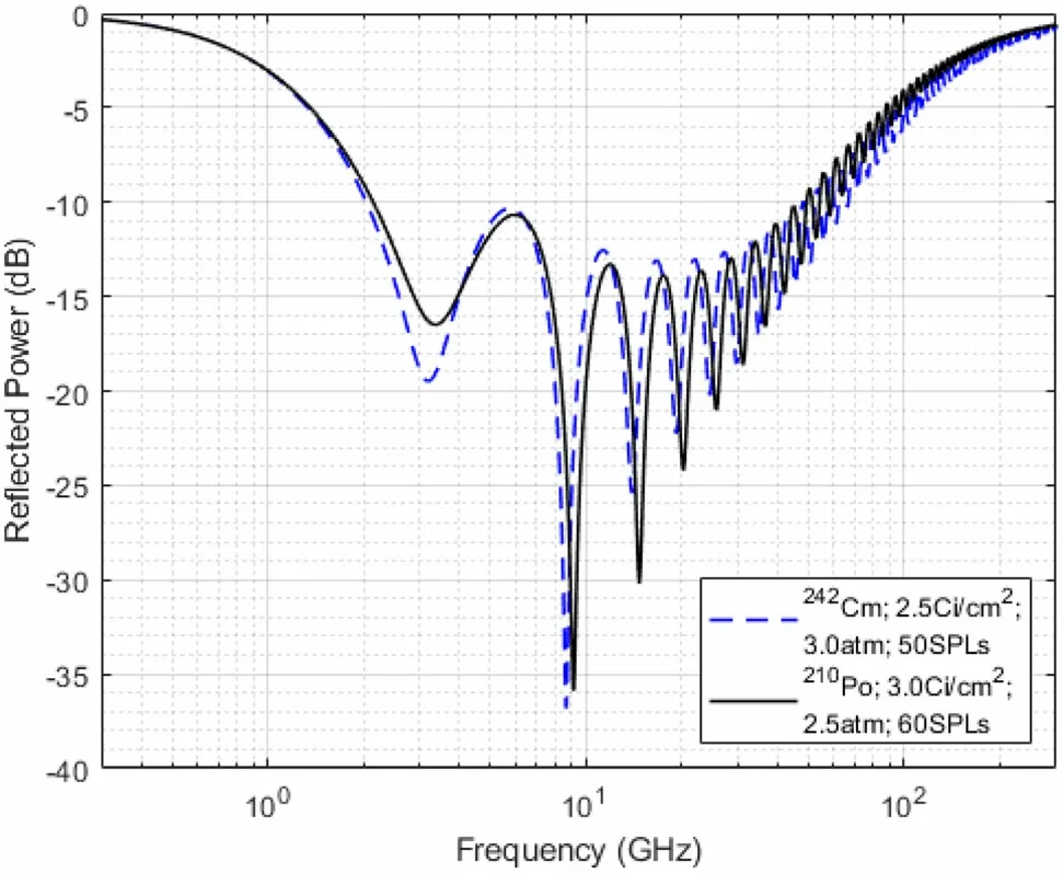
Fig.10 Optimized reflected power with different radionuclides while the encapsulated gas is CO2
First, there was no disturbance of plasma distribution from airflow, while the plasma was enclosed in MF microsphere shells. Second, only the atmospheric temperature affected the plasma in the shells;however,this could be neglected in the EMW attenuation based on the simulation results. Third, the gas and MF used to encapsulate the gas in the shells can together prevent radiation leakage,although the MF plays the primary role. Fourth, a broad attenuation bandwidth of 2–50 GHz, in which the EMW attenuation was over 10 dB,was obtained by modifying the adjustable parameters.Fifth,the stability of the EMF on the incident angle and polarization provides good stealth performance for targets under networked radar in the future.Sixth, this method is suitable for small-satellite radar stealth owing to its lightweight and self-provided plasma.
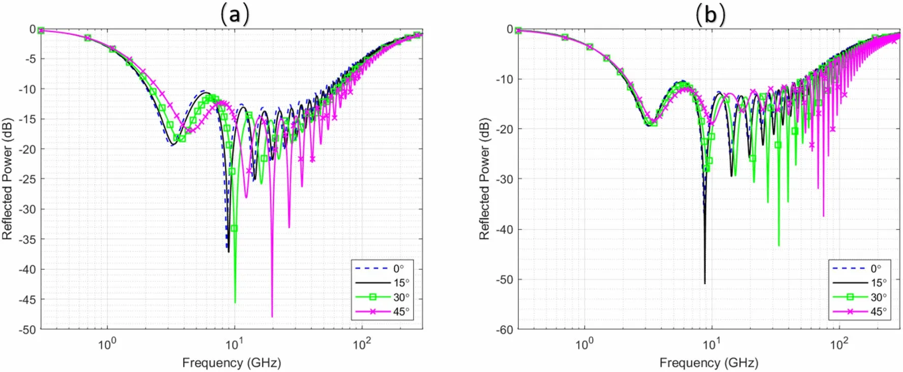
Fig. 11 (Color online) Reflected power of TE (a) and TM (b) waves with different incident angles and the optimized condition of 242Cm in Fig. 10
Author ContributionsAll authors contributed to the study conception and design. Material preparation, data collection and analysis were performed by Jin-Jian Yuan,Gui-Ping Meng,Min Gu and Run-Sheng Huang. The first draft of the manuscript was written by Jin-Jian Yuan, and all authors commented on previous versions of the manuscript. All authors read and approved the final manuscript.
杂志排行

Nuclear Science and Techniques的其它文章
- The role of deformations and orientations in an alpha ternary fission of Thorium
- Feedforward compensation of the insertion devices effects in the SSRF storage ring
- Development of an ultrafast detector and demonstration of its oscillographic application
- Low-radioactivity ultrasonic hydrophone used in positioning system for Jiangmen Underground Neutrino Observatory
- Study on analytical noise propagation in convolutional neural network methods used in computed tomography imaging
- Monte Carlo simulation of neutron sensitivity of microfission chamber in neutron flux measurement