Monte Carlo simulation of neutron sensitivity of microfission chamber in neutron flux measurement
2022-07-26ZePengWuXinBiaoJiangWenShouZhangChunLeiSuYongGangZhangSunLiHongBao
Ze-Peng Wu• Xin-Biao Jiang• Wen-Shou Zhang • Chun-Lei Su •Yong-Gang Zhang-Sun • Li-Hong Bao
Abstract Microfission chambers loaded with highly enriched fissile materials are widely used for measuring power in reactors. The neutron sensitivity of the microfission chamber is a key parameter that determines the accuracy of the power measurement. To evaluate the performance of the FC4A microfission chamber, in this work, we introduced an accurate and validated model of the microfission chamber, a performed Monte Carlo simulation of the neutron sensitivity of the microfission chamber with GEANT4 code, and conducted an irradiation experiment on the neutron irradiation effect platform #3 of the Xi’an Pulsed Reactor. We compared the simulated sensitivity with the experimental results, which showed that the sensitivity obtained from the simulation was in good agreement with the experimental results.In addition,we studied the impact of the design parameters of the fission chamber on the calculated neutron sensitivity of the microfission chamber.
Keywords Microfission chamber ∙Neutron sensitivity ∙Monte Carlo simulation ∙GEANT4
1 Introduction
Neutron flux is an important parameter of a neutron radiation field, and fission chambers are widely used as online monitors for neutron diagnostics, code validation purposes, and accurate reactor power determination.Operation staff must control reactors and ensure their safety [1–3].
In general,a fission chamber is a gas ionization chamber loaded with a fissile material,being mainly composed of a stainless casing, filling gas, and fissile layer, such as235U,238U and232Th, which are usually plated on the cathode.The fission fragments produced by the fission reaction cause ionization of the filling gas and produce pulsed signals [4]. Because of the high energy of the fission fragments emitted from the fissile coating,the amplitude of the signal produced by high-energy deposition is much higher than that of the signals caused by other sources of noise or gamma interference. This enables the signal-to-noise ratio of fission chambers to be higher than those of other detectors. The first fission chambers were produced in the 1940s under the Manhattan Project and matured in the 1950s [5]. Since then, most reactors have used fission chambers as online power monitors to enable fine reactivity control.
With the development of technology, fission chambers have gradually been miniaturized. Briefly, a microfission chamber is a pencil-sized fission chamber.In the 1960s,the Commissariat al’Energie Atomique et aux Energies Alternatives (CEA) manufactured microfission chambers for an experimental nuclear reactor in France[5].They are widely used for fusion reactor power measurements,such as in the joint European torus (JET), tokamak fusion test reactor(TFTR), JT-60U, and international thermonuclear experimental reactor (ITER) [6]. Usually, the neutron monitor is installed far from the fusion core, which may reduce measurement accuracy owing to the presence of thick shielding blankets. Consequently, an in-vessel microfission chamber is the ideal tool for power measurement. In fusion power measurements, the nuclear heat and burn-up of the fissile material are predominant; therefore,different types of microfission chambers have been designed for different use cases. Microfission chambers(MFCs) are suitable for neutron flux measurement in narrow spaces and less disturb the neutron flux [7–9].
The real-time counting rate is measured in the microfission chamber in pulse mode,which is related to the neutron flux rate through neutron sensitivity. Borella et al.calculated the impact of the235U fission chamber design on neutron sensitivity using MCNPX Version 2.7.0 to complement the missing technical data [1]. Jammes et al. calculated the sensitivity and loss of a uranium fission chamber for the design of new fission chambers with thicker coatings using Monte Carlo code,and found an 8%linear relation [5]. Hence, the neutron sensitivity of a microfission chamber must be measured. Under ideal conditions, without self-shielding and -absorption effects,the neutron sensitivity of the detector depends only on the amount of fissile material. In general, the sensitivity ε is defined as [1]:

where C is the count rate, and Φ is the total neutron flux.
In this study,we used GEANT4 software to simulate the neutron sensitivity of the FC4A microfission chamber on the neutron irradiation effect platform #3 of the Xi’an Pulsed Reactor. We compared the simulation with the experimental results, and discussed the factors that impact the neutron sensitivity of the MFC.
2 Experimental methods
2.1 Experimental setup
The Xi’an Pulsed Reactor(XAPR)is a TRIGA research reactor fueled by UHZr1.6alloy at the Northwest Institute of Nuclear Technology, China. The XAPR is equipped with many types of experimental and irradiation facilities for a variety of research purposes, such as neutron activation analysis, material irradiation performance, and detector calibration[10].Owing to the high hydrogen content in the fuel, the neutron spectrum of XAPR is nearly thermal and has a relatively low fast-neutron component. To enhance the ability to study fast-neutron effects in the XAPR, several experimental platforms have been developed to absorb thermal neutrons and gamma rays to enhance the fast-neutron component and n/γ ratio. The neutron irradiation effect platform #3 is an important experimental platform that combines B4C and Pb to enable testing the effects of fast-neutron irradiation on electronic systems or components, having an inner space of approximately 350 mm × 300 mm × 290 mm and a maximum load capacity of 150 kg. Figure 1a, b shows a photograph and schematic illustration of the neutron irradiation effect platform #3, respectively. We placed the MFC in front of neutron irradiation effect platform#3,as shown in Fig. 1c.
Multifoil activation is recommended by the American Society for Testing Material(ASTM)for neutron spectrum measurements [11], and many neutron spectrum unfolding methods have been proposed, such as the SAND-II and other iterative methods [12–20]. Multifoil activation has little impact on the neuron radiation field and does not interfere with gamma-rays; however, it is only suitable for offline neutron spectrum measurements of stable neutron radiation fields, and the entire spectrum resolution process is complicated and time-consuming. Figure 1d shows the neutron spectrum at the front position of neutron irradiation effect platform #3, which we obtained by the SAND-II iterative method [19] using the theoretical initial neutron spectrum calculated by OpenMC 0.11.0 with the ENDF/BVII.1 library [21] and the multifoil activation results as input. To obtain the initial neutron spectrum, we constructed an accurate XAPR reactor model, including fuel rod distribution, structural materials, large water tank,control rods, and heavy concrete shielding, in OpenMC.We used foils including197Au,59Co,115In,58Ni,54Fe,and32S to measure the reaction rates at different neutron energies.
2.2 Data acquisition system
For data acquisition, we used a shaping preamplifier MRS-2000 (Mesytec, Putzbrunn, Germany) and an Eagle2000 multichannel analyzer, including two Series 5000 MCArds (APTEC, PA, USA) [22]. The MRS-2000 shaping amplifier is a preamplifier designed for neutron counters, especially those perform preamplifying, shaping,and amplitude screening functions [23]. Both amplitude and TTL(Transistor-Transistor Logic) signals can be exported at the request of the user.The MRS-2000 shaping amplifier has a high-voltage input that provides the high voltage required for microfission chambers. To ensure that the microfission chamber was in a suitable working state,we set the high voltage of the microfission chamber to 500 V. The Eagle2000 multichannel analyzer is a comprehensive nuclear radiation information acquisition instrument that is suitable for random information acquisition[22].Figure 2 shows a diagram and photograph of the data acquisition system of the MFC.

Fig.1 (Color online)Photograph of neutron irradiation effect platform#3(a);profile(b),front position of microfission chamber(MFC)(c),and neutron spectrum of front position (d) of neutron irradiation effect platform #3
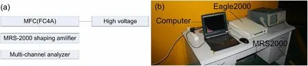
Fig. 2 (Color online) Diagram (a) and photograph (b) of data acquisition system
3 Simulation
3.1 MFC model
GEANT4 software is a C++ program developed by CERN used for simulating particle transportation and the reaction process, and is widely used for the calculation of high-energy physics, medical physics, and shielding[24–32]. To determine the neutron sensitivity of the MFC,we used the Monte Carlo simulation code in GEANT4 to construct the MFC model based on the technical data,which we obtained from the manufacturer, using the G4VphysicalVolume module[24].The model,as shown in Fig. 3b,includes232Th coating,alloy shell,and filling gas.Table 1 lists the technical data reported by the manufacturer.

Fig. 3 (Color online) Photograph (a) and schematic illustration (b) of MFC model; direction of incident neutrons (c)
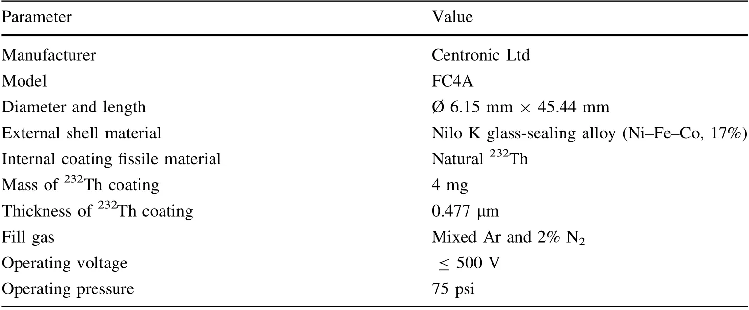
Table 1 MFC technical data as specified by the manufacturer
3.2 Incident neutron source
Figure 3c illustrates the direction of the incident neutrons. The incident neutron source was a uniformly distributed rectangular plane source.The length of the neutron source was equal to that of the232Th coating along the zaxis; its width was equal to the232Th coating diameter along the y-axis. The neutron source was located at the x = 12 mm plane, and its direction was along the negative direction of the x-axis, so the incident neutron covered the projection area of the232Th coating in the yz plane. The energy distribution of the incident neutron source followed the neutron spectrum at the front position of neutron irradiation effect platform #3 (Fig. 1d), and we used discrete energy bins as recommended by the ASTM-E-722 standard for simulation [11]. The neutrons at the front position of the neutron irradiation effect platform #3 directly came from the reactor and from the neutrons reflected in the irradiation platform; we already accounted for this effect with the spectrum. We used the G4ParticleGun module [24] to describe the neutron sources according to the direction and energy distribution specifications provided above. In addition, to discuss the factors influencing the neutron sensitivity of MFC (Sect. 4), we chose different neutron energies from 2 to 15 MeV to calculate the neutron sensitivity of the MFC for different thicknesses of the232Th fissile coating and MFC alloy shell.
3.3 Pulse signal generation conditions
The incoming neutrons hit the fissile target232Th, and high-energy fission fragments were produced in opposite directions,some of which moved toward the filling gas and deposited part of the energy in the gas and produced signals,while others were not(i.e.,others were trapped by the coating). The alpha particles produced by the spontaneous decay of the fissile material were the main source of noise in the detection signal of the microfission chamber. The charge signal produced by an alpha particle needs to be separated from the signals produced by the fission fragments in the filling gas. The maximum alpha energy is approximately 6 MeV for actinides such as235U,238U and232Th [3]; therefore, we set the threshold energy of the ejected particle to 6 MeV as one of the pulse signal generation conditions.Figure 4 depicts the flow diagram of the simulation process.To obtain the distribution of the fission fragments of232Th, we modified the LBE (Low Background Experiment) physics code [33] to link the fission production data files. We defined a pulse signal when the following conditions were satisfied, then we stopped the transportation of particles: (1) the nuclear charge number of the ejected particle was greater than 2, owing to the interference of the pulse amplitude spectrum of alpha particles produced by the spontaneous alpha decay of fissile materials and protons from the (n, p) reaction; (2) the energy of the ejected particle was greater than 6 MeV,owing to the high energy of the two ejected fission fragments, which was approximately 200 MeV, and the interference of alpha particles; and (3) the position of the next point of the ejected particle was located in the sensitive region (the gas-filled region) of the MFC.
3.4 Other phenomena and their impact on MFC neutron sensitivity
Theoretically,a pulse signal should be produced when a fission event occurs in an MFC. However, the following effects are required to determine the actual neutron sensitivity of the MFC:
(1) Self-shielding effect A microfission chamber is loaded with fissile material and has an alloy shell, electrode, and other structural materials. Owing to the influence of the structural material and geometry of the microfission chamber, the neutron spectrum is inconsistent with the external neutron radiation field when the neutron reaches the fissile coating. When the neutron is transported to the interior of the fissile coating, it undergoes a fission reaction with the fissile material that gradually absorbs the neutron.This results in the neutron flux reaching the innermost part being lower than that reaching the outermost part, which is collectively referred to as the self-shielding effect.
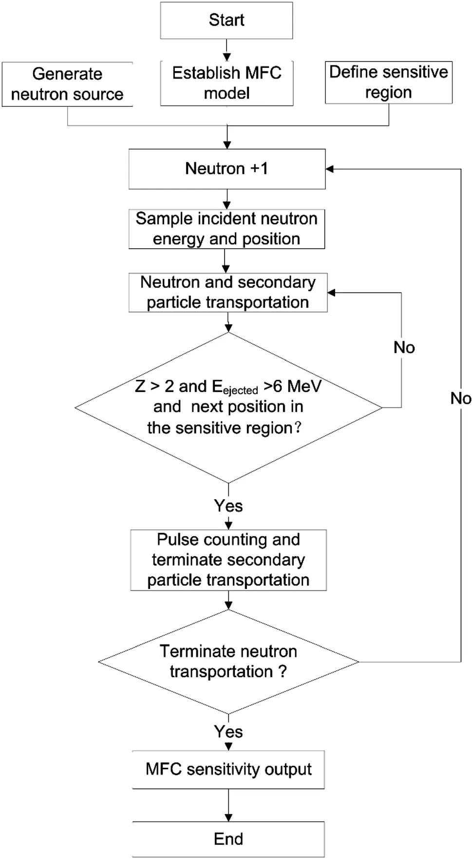
Fig. 4 Flow diagram of simulation process
(2) Self-absorption effect When neutrons reach the fissile material, highenergy fission fragments (heavy charged particles)are produced by a fission reaction. As the fissile coating has a certain thickness,some primary fission fragments at deep positions in the fissile material ill lose most of their energy before reaching the gas or even become trapped by the fissile coating.
(3) Wall effect Fission fragments emitted from the fissile material interact with the filling gas and do not lose all their energy in the filling gas. The fragments may hit the electrode,fissile coating,or alloy shell,and lose their energy in these materials.
(4) Energy threshold Many low-frequency noises may be present in the outdoor environment as well as the noise produced by gamma rays and alpha particles from the spontaneous alpha decay of the fissile material. Therefore, the energy threshold must be properly set to eliminate the interference caused by low-frequency noise. This also results in the loss of signal from fission fragments that do not deposit sufficient energy in the gas.
(5) Dead time effect When the frequency of the pulses is much higher than the system resolution frequency,the subsequent pulses are not considered, which results in these signals being missed.When using GEANT4 software to determine detector sensitivity,we accounted for effects(1)–(4)in the simulation. We corrected effect (5) using a multichannel analyzer.
To more clearly demonstrate these effects, we considered different structural materials and different fission material thicknesses to study the self-shielding and -absorption effects,and their impact on the neutron sensitivity of the MFC. As such, we selected different MFC shell thicknesses, which ranged from 1.5 to 6.5 mm, and different232Th fissile coating thicknesses,which ranged from 0.477 to 700 μm, to study the self-shielding and self-absorption effects, respectively. We chose an incident neutrons energy range of 2 to 15 MeV because of the threshold energy of the232Th fission reaction.
4 Results and discussion
4.1 Measured MFC neutron sensitivity of neutron irradiation effect platform #3
One of the two fission fragments produced by the fission reaction and emitted toward the filling gas should deposit sufficient energy in the filling gas to produce detectable signals. The other, traveling in the opposite direction, should be trapped by the fissile coating or the alloy shell. The worst case occurs when fission fragments are emitted perpendicular to the fissile coating, and the position of the charges in the filling gas is located at the middle of the gap between the two electrodes.The induced charge qoutis derived from Eq. (2) using the Ramo–Shockley theorem:
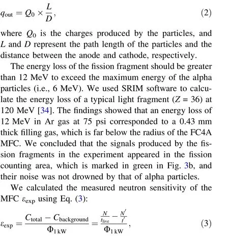
where Ctotaland Cbackgroundare the total fission and background count rates, respectively; Φ1kWis the total neutron flux of the front position of neutron irradiation effect platform #3; N and N’ represent the total fission and background counts, respectively; tliveand t’ are the lifetimes of the fission counts and background counts,respectively.
We obtained the corresponding fission counting rate using an Eagle2000 multichannel analyzer with a reactor power of 1 kW and a real time of approximately 30 min.Figure 5 shows the measured and background spectra of the MFC. The left-hand side of the spectrum, marked in blue in Fig. 5,represents the noise below the threshold,and the right-hand side of the spectrum, marked in green,represents the fission count. When we operated the XAPR at 1 kW, we determined that the total number of fission counts N was approximately 34,366 by summing the green counts in Fig. 5a.The live time tlivewas 1492 s.When the XAPR was shut down, we determined the background count N’ was approximately eight by summing the green counts in Fig. 5b. The live time t’ was 219 s. Hence, we found that the background count rate was small (approximately 0.04 s–1) and had little effect on the experimental results.
When the power of the XAPR was 1 kW, the total neutron flux at the front position of the neutron irradiation effect platform #3 Φ1kWwas approximately(1.012 ± 0.102) × 108n∙cm–2∙s–1(k = 2), which we determined by applying the multifoil activation method.Therefore, the measured neutron sensitivity of MFC εexpwas approximately (2.277 ± 0.229) × 10–7cm2(k = 2).
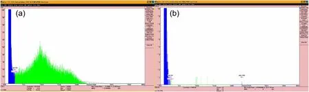
Fig. 5 (Color online) Measured (a) and background (b) spectra of the MFC
4.2 Simulated MFC neutron sensitivity of neutron irradiation effect platform #3
For the simulation conditions described in Sect. 3,Table 2 lists the results of the simulated neutron sensitivity of the MFC that we obtained using GEANT4 software.We sampled the incident neutron energy in the GEANT4 program according to the probability distribution of the neutron spectrum of neutron irradiation effect platform #3.Because the threshold of the232Th fission reaction is approximately 800 keV, neutrons with energies below the threshold do not undergo fission within the232Th fissile target. Therefore, to improve the sampling efficiency of GEANT4 software, we sampled only neutrons with energies greater than 800 keV.
4.3 Comparison
The relative deviation between the simulated neutron sensitivity of the MFC and the measured neutron sensitivity of the MFC was approximately 5.88%.The simulated and experimental results were in good agreement,verifying the reliability of using the Monte Carlo GEANT4 software to simulate the neutron sensitivity of the MFC.
4.4 Self-shielding effect
As mentioned in Sect. 3.4, the fissile material, alloy shell, electrode, and other structural materials produce a self-shielding effect. We considered different thicknesses of232Th fissile coating and MFC alloy shell in this study.These two thicknesses are the main factors influencing the neutron sensitivity of an MFC.
If the self-shielding effect is not considered, that is, the incident neutrons are not absorbed by the alloy shell or fissile coating, the neutron sensitivity of the MFC is only related to the neutron energy, cross section of the fissile material, and amount of fissile material. The ideal neutron sensitivity is derived from Eq. (1):

where E and V are the neutron energy and the effective volume of the fissile material, respectively; φ(r, E) and σ(E)are the differential neutron flux and differential fission cross section,respectively;N is the atomic number density of the fissile material;σavgis the mean cross section of the(n,f)reaction with the fissile material;NAis the Avogadro constant; and m and M represent the mass and atomic weight of the fissile material, respectively.
To consider the self-shielding effect, we calculated the neutron sensitivity of the MFC using GEANT4 software with conditions(1)and(2)described in Sect. 3.3.As such,one less constraint was applied on the region of the particle; therefore, once the fission reaction occurred in the fissile coating, two rejected fission fragments traveling in opposite directions were recorded, resulting in two fission counts.

Table 2 Result of simulation of neutron sensitivity of MFC of neutron irradiation effect platform #3
(1) Different.232Th fissile coating thicknesses The different232Th fissile coating thicknesses caused different neutron sensitivity losses in the microfission chamber. For the microfission chamber with a certain shell thickness, we calculated the impact of the self-shielding effect on the detector sensitivity for a 2 MeV monoenergy incident neutron(Fig. 6a).The neutron fission cross section of232Th fissile material corresponding to 2 MeV was approximately 0.12 barn, which we found in the neutron crosssectional database ENDF/B-VII. According to Eq. (4),the theoretical neutron sensitivity is approximately (1.246 ± 0.024) × 10–6cm2(k = 2) when the thickness of the 4 mg fissile coating is 0.477 μm.The detector sensitivity loss was approximately 0.02%. We calculated the neutron sensitivities for232Th coatings ranging from 0.477 to 700 μm using GEANT4 software and the theoretical method, and the largest sensitivity loss was approximately 0.86%when the fissile coating was 700 μm. This showed that the impact of the self-shielding effect of the232Th fissile material was less than 1% when the thickness of the fissile coating was less than 700 μm.The self-shielding effect of the fissile coating was weak because the energy of the incident neutron was high enough to easily penetrate the fissile coating,and the total neutron cross section of232Th was not very high.The results are consistent with the neutron flux perturbation findings reported by Jammes et al.using fast neutrons [5].235U is also widely used as fissile material in MFC. Jammes et al. [5], when using235U as fissile material, found that the threshold of the fission reaction should not be considered.The fissile coating had a strong impact on the selfshielding effect because the energy of the incident neutron was too low to penetrate the fissile coating,and the total neutron cross section of235U was very large, which resulted in a large sensitivity loss.

Fig. 6 (Color online) Comparison of the theoretical and actual neutron sensitivity considering the self-shielding effect at 2 MeV(k = 2) (a); relationship between the MFC neutron sensitivity and MFC shell thickness(k = 2) (b),between the MFC neutron sensitivity and the 232Th fissile coating thickness (k = 2) (c), and between the MFC neutron sensitivity loss and the.232Th fissile coating thickness(k = 2) (d)
(2) Different MFC alloy shell thicknesses Different MFC alloy shell thicknesses resulted in different neutron sensitivity losses in the microfission chamber. Figure 6b presents the relationship between the neutron sensitivity of the MFC and the thickness of the MFC shell, which ranged from 1.5 to 6.5 mm. This showed that the detector sensitivity decreased as the shell thickness of232Th MFC increased.The thicker the shell,the stronger the selfshielding effect. The rate at which the detector sensitivity decreased was approximately the same as that for fast neutrons with different energies because the232Th fission cross section for fast neutrons with different energies differed little.Therefore,to reduce the self-shielding effect of the MFC shell, a thin shell that satisfies the mechanical conditions should be selected.
4.5 Self-absorption effect
As mentioned in Sect. 3.4, a fissile material with a certain thickness produces a self-absorption effect.Neutron sensitivity loss occurs because of the self-absorption effect.In Sect. 4.4, we calculated the neutron sensitivity considering only the self-shielding effect caused by the thickness of the fissile coating using GEANT4 software with conditions (1) and (2) described in Sect. 3.3. We obtained a series of neutron sensitivities considering the self-shielding and self-absorption effects with conditions(1),(2),and(3)described in Sect. 3.3, when the thickness of the232Th fissile coating ranged from 0.477 to 700 μm. We obtained the neutron sensitivity loss caused by a certain thickness of the fissile material from Eq. (5):
where η represents the neutron sensitivity loss; ε1and ε2represent the neutron sensitivity considering only the selfshielding effect and neutron sensitivity considering both the self-shielding effect and self-absorption effect,respectively.
Figure 6c shows the relationship between the neutron sensitivity of the MFC and the232Th fissile coating thickness, which ranged from 0.477 to 700 μm. This indicated that the neutron sensitivity of the232Th MFC first increased and then decreased as the thickness of232Th fissile coating increased. This occurred because the self-absorption effect was weak when the coating was thin, the increase in coating thickness increased with the amount of fissile material, and the detector sensitivity gradually increased with the increase in coating thickness. However, when the coating thickness increased to a certain value, the selfabsorption effect of the coating thickness became dominant, and the detector sensitivity decreased. Therefore, to ensure neutron sensitivity of a232Th MFC is high, we recommend a coating thickness of 10 μm.
Figure 6d shows the relationship between the neutron sensitivity loss of the MFC and the232Th fissile coating thickness in the range of 0.477 to 700 μm. The findings showed that the neutron sensitivity loss of the232Th MFC first slowly and then rapidly increased as the232Th fissile coating thickness increased.Finally,the neutron sensitivity loss of the232Th MFC was close to 100%. Although the self-absorption effect was weak when the fissile material was thin, it slowly increased with the increase in coating thickness, which resulted in a slow increase in the neutron sensitivity loss. As the coating thickness increased, most fission fragments were trapped by certain thicknesses of232Th fissile coating; therefore, the neutron sensitivity loss rapidly increased until the coating thickness reached 100%.This finding also showed that the maximum increase was approximately 3 μm, which is in good agreement with the findings reported by Jammes et al. [5], according to which the neutron sensitivity loss becomes substantially larger when the fissile coating thickness is 2 mg/cm2. The fissile material we used in this study was U3O8, which had a density of approximately 7.29 g/cm3. Therefore, the fissile material was approximately 2.7 μm. The highest neutron sensitivity loss reported by Jammes et al. owing to selfabsorption was approximately 8% when the fissile coating thickness was 1 mg/cm2(i.e., fissile coating thickness was approximately 1.4 μm) [5]. This result is in good agreement with the neutron sensitivity loss that occurred with the same fissile coating thickness in this study, which was approximately 9%. The comparison showed that the trend in the neutron sensitivity loss of the MFC in this study is consistent with that determined by Jammes et al. [5]. In principle, the self-absorption effect caused by the trapping of fission fragments is related to the stopping power of the fissile material. Because of the similar material constitutions considered in the two studies,the stopping powers of the fissile materials should be similar.
5 Conclusion
In this study, we established an effective method for simulating the neutron sensitivity of an MFC, and studied the self-shielding and -absorption effects caused by different MFC alloy shell and232Th fissile coating thicknesses. We found that the detector sensitivity decreased with an increase in the shell thickness for the232Th MFC owing to the self-shielding effect; therefore, a thin shell that meets the mechanical conditions should be selected.We also found that the neutron sensitivity of the232Th MFC first increased and then decreased as the thickness of the232Th fissile coating increased owing to the self-absorption effect. Therefore, we recommend a 10 μm thick coating to achieve high neutron sensitivity. The good agreement between the simulation and experimental results regarding detectable fission events indicated that the proposed simulation can be used as a guide for experiments.The simulation considers many factors that affect the neutron sensitivity of an MFC and enables the calculation of the neutron sensitivity of the MFC for different sourcedetector geometries. We constructed an important and innovative simulation method for the future design of MFCs and other detectors that accurately obtains neutron fluxes in different neutron fields.
AcknowledgementsWe thank the operation staff at the Xi’an Pulsed Reactor for helping us to install the measuring system.We also thank Dr.Wang at the China Academy of Engineering Physics for providing the232Th microfission chamber.
Author contributions All authors contributed to the study conception and design. Material preparation, data collection and analysis were performed by Wen-Shou Zhang, Chun-Lei Su, Yong-Gang Zhang-Sun and Li-Hong Bao. The first draft of the manuscript was written by Ze-Peng Wu, and all authors commented on previous versions of the manuscript. All authors read and approved the final manuscript.
杂志排行

Nuclear Science and Techniques的其它文章
- The role of deformations and orientations in an alpha ternary fission of Thorium
- Feedforward compensation of the insertion devices effects in the SSRF storage ring
- A new radar stealth design excited by 210Po and 242Cm
- Development of an ultrafast detector and demonstration of its oscillographic application
- Low-radioactivity ultrasonic hydrophone used in positioning system for Jiangmen Underground Neutrino Observatory
- Study on analytical noise propagation in convolutional neural network methods used in computed tomography imaging