MeshCNN-based BREP to CSG conversion algorithm for 3D CAD models and its application
2022-07-26YueTongLuoHuaDuYiManYan
Yue-Tong Luo• Hua Du• Yi-Man Yan
Abstract In the field of neutronics analysis, it is imperative to develop computer-aided modeling technology for Monte Carlo codes to address the increasing complexity of reactor core components by converting 3D CAD model(boundary representation, BREP) to MC model (constructive solid geometry, CSG). Separation-based conversion from BREP to CSG is widely used in computer-aided modeling MC codes because of its high efficiency, reliability, and easy implementation. However, the current separation-based BREP-CSG conversion is poor for processing complex CAD models,and it is necessary to divide a complex model into several simple models before applying the separation-based conversion algorithm,which is time-consuming and tedious. To avoid manual segmentation, this study proposed a MeshCNN-based 3D-shape segmentation algorithm to automatically separate a complex model. The proposed 3D-shape segmentation algorithm was combined with separation-based BREP-CSG conversion algorithms to directly convert complex models.The proposed algorithm was integrated into the computeraided modeling software cosVMPT and validated using the Chinese fusion engineering testing reactor model. The results demonstrate that the MeshCNN-based BREP-CSG conversion algorithm has a better performance and higher efficiency, particularly in terms of CPU time, and the conversion result is more intuitive and consistent with the intention of the modeler.
Keywords BREP to CSG conversion ∙Computer-aided modeling ∙cosVMPT ∙Intelligent pre-segmentation ∙MeshCNN This work was supported by the National Key R&D Program of China(Nos. 2019YFE03110000 and 2017YFE0300501) and the Chinese National Natural Science Foundation (No. 11775256).
1 Introduction
The first 3D boundary representation (BERP) to constructive solid geometry (CSG) conversion algorithm is an improved 2D ASV [1] algorithm. Although the improved ASV is easy to implement, its convergence cannot be guaranteed and it is only suitable for converting polyhedrons. Shapiro [2, 3] presented a solution to the BERPCSG conversion for 3D solids in the 1990s, in which they solved a general conversion problem from BREP to halfspace-based CSG. Shapiro proposed three concepts for generalizing the BERP-CSG algorithm: canonical intersection, a describable theorem based on half-spaces of boundaries, and half-space separation. The proposed algorithm can be used to construct half-space-based CSGs for solids bound by quadric surfaces.Moreover,half-space domination was proposed to simplify the CSG representation of a solid. Suzanne [4]proposed the BHC algorithm based on the fundamental work of Shapiro et al., who presented an effective representation method for an intermediate model that avoids the extra computation of computing a resultant solid after each pass of dominating half-space factorization. Additionally, half-spaces are factored one at a time,avoiding the additional post-processing computation required to minimize the resultant CSG-tree.Shapiro and Suzanne laid the theoretical foundation for 3D BREP-CSG conversion.
Monte Carlo (MC) particle transport codes [5] are widely used in the field of nuclear analysis, and require a 3D CSG model as the input. With the increasing complexity of nuclear facilities, it is necessary to use CAD software for modeling;however,the resulting model is the BREP model.Therefore,it is crucial to develop computeraided modeling technologies to satisfy the conversion demands of CAD models (BREPs) to MC models (CSGs).To conduct this conversion,Luo[6]proposed a separationbased BREP-CSG conversion algorithm based on the theories of Shapiro and Suzanne. The core idea is to decompose a complex CAD model into a set of simple convex solids by using Boolean operations. The corresponding convex solids are represented by half-spaces of the boundary surfaces. Separation-based BREP-CSG conversion is reliable and easily implemented, resulting in software development for computer-aided modeling,including MCAM [7–9] and McCAD [10–12].
However, separation-based BREP-CSG conversion relies heavily on a large number of Boolean operations because it is time consuming and error-prone, particularly for models with complex structures. Additionally, the likely occurrence of excessive decomposition reduces the conversion efficiency and increases the computation time of the MC code. Luo [13] proposed feature-based BREPCSG conversion to optimize BREP-CSG conversion, the basic idea of which is to identify the predefined features of a model using feature recognition technology. These features were used as tree nodes, and a separation-based BREP-CSG conversion was employed to convert each feature. Unfortunately, the model characteristics are inconspicuous or features are difficult to define.This limits the applicability of the proposed algorithm. Other optimization techniques [12] have been proposed to improve conversion efficiency, including replacing Boolean operations with triangle collisions, adding an auxiliary splitting surface algorithm to reduce the generation of irregular solids, and introducing a priority-sorting algorithm for splitting surfaces. Although the optimized conversion algorithm improved the conversion efficiency and stability,it required rules of thumb summarized by users. These rules frequently rely on low-level geometric elements,such as edges and faces, without considering the high-level features of the 3D models. Moreover, owing to the limitations of these rules, it is extremely difficult, or even impossible, to find a universal rule for all models.Therefore, it is necessary to manually preprocess a complex model before conversion to avoid errors, particularly when converting a model with highly complex structures,such as the Chinese fusion engineering testing reactor(CFETR) [14, 15]. Figure 1 shows diagrams of the complex models. Relatively regular models are obtained through manual preprocessing and can be converted using computer-aided modeling software (e.g., cosVMPT).However, manual model preprocessing is time-consuming and tedious, and it is imperative to develop model preprocessing technology.
Manual model preprocessing decomposes a complex model into relatively regular sub-models according to the intention of the modeler. Generally, this process can be categorized as a 3D shape segmentation. To date, several studies have been conducted on 3D-shape segmentation[16–20]. Compared with other methods, deep learningbased segmentation has been widely studied owing to its effectiveness (see Sect. 2). Considering the high similarity between components, as shown in Fig. 2a, the vacuum vessel (VV) shares similar component structures with the thermal shield(TS).Moreover,there are some components in the other sectors, as shown in Fig. 2b. Therefore, considering the characteristics of a fusion model, deep learning-based 3D-shape segmentation can play a significant role in 3D model preprocessing.Accordingly,an intelligent pre-segmentation algorithm is proposed to learn preprocessing rules by inputting pre-segmented cases, with the learned rules then used to guide complex model segmentation.
The cosVMPT [21, 22] is a visual modeling platform that converts CAD models into MC models and utilizes OpenCascade (OCC) as a CAD geometry engine. The FreeCAD framework is a graphical user interface, and VTK provides data visualization. The cosVMPT was successfully applied to complex CFETR fusion devices comprising tens of thousands of solids (Fig. 3), including the plasma chamber, blanket, divertor, cryostat, VV, TS, toroidal field coil (TFC), poloidal field coil, and central solenoid. An intelligent pre-segmentation algorithm was proposed to optimize the BREP-CSG conversion algorithm to prevent the need for manual intervention in model preprocessing and improve the conversion performance.Intelligent pre-segmentation is a combination of deeplearning-based 3D model segmentation with separationbased BREP-CSG conversion.The 3D model segmentation algorithm was used to learn the preprocessing rules for the segmentation of the CAD model and intermediate model generation, according to the intention of the modeler. A separation-based BREP-CSG conversion algorithm was used to convert the intermediate models to optimize BREPCSG conversion. An intelligent pre-segmentation algorithm was applied to cosVMPT and applied practically.
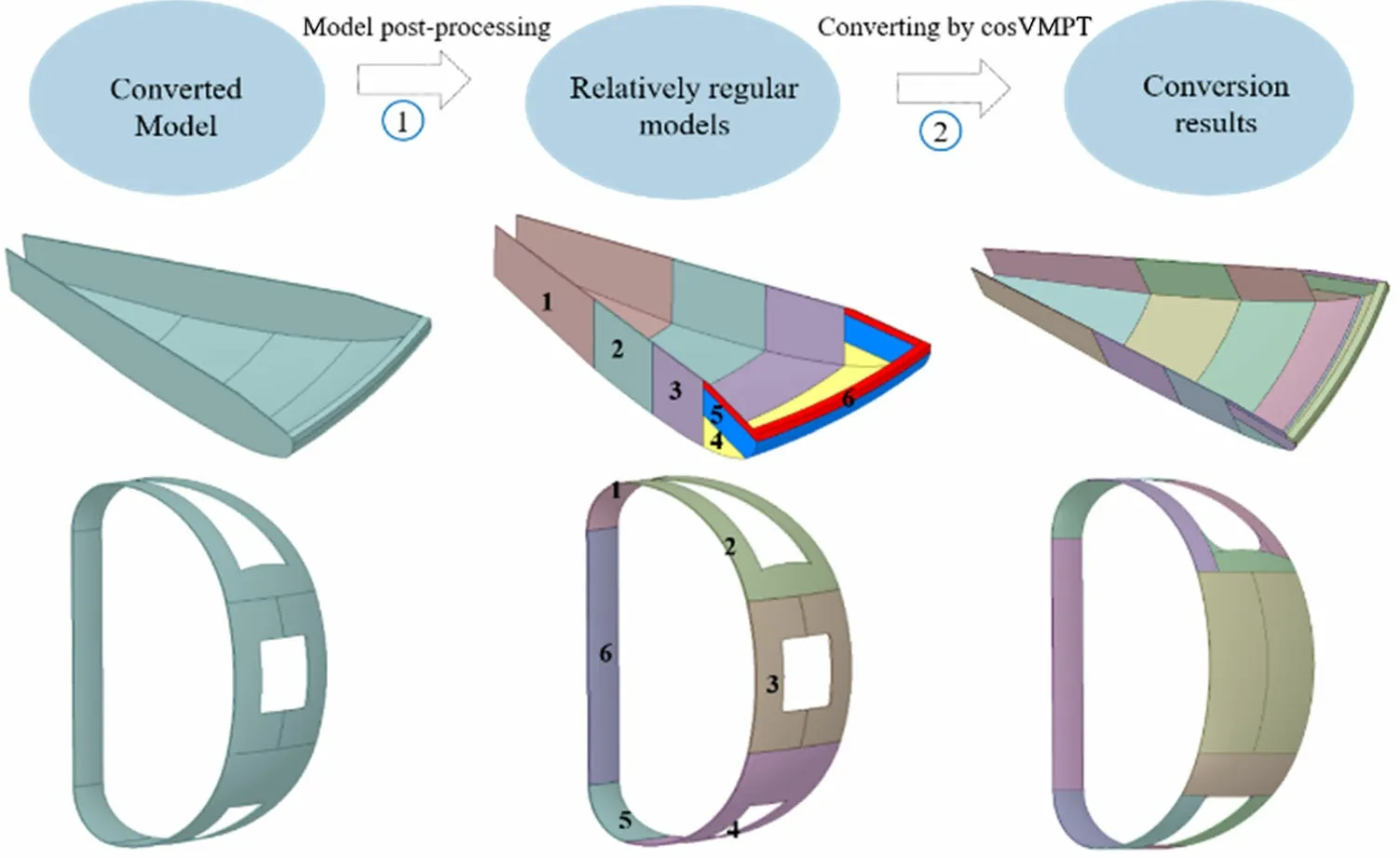
Fig. 1 (Color online) Diagrams of the conversion of certain complex models

Fig. 2 (Color online) A fusion component with high similarity

Fig. 3 (Color online) CAD engineering model of the CFETR
2 3D-shape segmentation algorithm
3D-shape segmentation technology has remained a research hotspot in the field of computer graphics. It has been widely used in model retrieval, feature recognition,and model reconstruction. Traditional segmentation methods, such as a conditional random field [23] and extreme learning machine [24], require manual definition of 3Dshape feature descriptors. The quality of feature extraction directly affects segmentation quality and directly depends on the quality of manually defined feature descriptors. In recent years,Convolutional Neural Networks(CNNs)have demonstrated excellent performance (recognition, classification, and object detection) in image classification,semantic segmentation, target detection, and other tasks.Compared to a traditional neural network,a CNN adopts a convolution kernel to extract features automatically. Generally,CNN concepts are useful for 3D-shape segmentation algorithms. The intrinsic data structure of a 3D-shape representation file does not resemble the regular and ordered datasets of images required by the CNNs. This leads to difficulties in the direct convolution of these 3Dshape representations. In light of the inadaptability of CNNs to the irregular structures of datasets, tricky strategies have been adopted to avoid convolution.For example,3D shapes are typically converted into regular 3D voxel grids [18] or sets of images [19] (e.g., multi-views).Although volumetric representations have the advantage of simplicity,they are time consuming and require significant computational resources.
Point clouds are the simplest representation of 3Dshaped data because a point-cloud-based technique is superior in terms of easily accessible data acquisition and simple representation. Additionally, it is convenient to convert them into other representations. Therefore, CNNs for point clouds have been proposed in recent years.PointNet [20] is a representative application of a CNN for irregular and sparse point clouds and adopts a T-Net to obtain a transformation matrix that is used to initialize the point cloud and ensure the invariance of rotation and translation. To make the model invariant to input permutation, a symmetric function was designed to solve the disorder of the point cloud. Although PointNet is efficient,Multi-Layer Perceptron (MLP) is performed on a single point, ignoring local information, and its performance is poor for 3D shape segmentation. Furthermore, the density of cloud data was not considered in PointNet. Inspired by CNNs, PointNet++ [25] was proposed to partition points into local regions, extract local features at multiscale and multiresolution, and obtain deep features using a multilayer network structure. PointCNN [26] is a generalized CNN capable of handling irregular data represented in point clouds. The core of PointCNN is the X-Conv operator,which weighs and permutes input points and features.
Mesh is another representation used to draw and store 3D models in computer graphics.The primary advantage of mesh representation is that a significant amount of information can be easily stored in less memory.For example,a large but simple surface can be represented by a small number of polygons. Another advantage of a mesh is its connectivity. However, the intrinsic data structure of the mesh representation is complex and irregular.For example,the number of elements in a mesh may vary significantly between different 3D shapes, and their permutations are arbitrary.Despite these problems,meshes are more capable of describing 3D shapes than are other representation methods.In this case,effectively using a mesh to represent 3D graphics is a new challenge and related studies are limited. Recently, MeshCNN [17], which is specifically designed for triangular meshes, has been invariant to translation, rotation, and scaling. Simultaneously, convolution and pooling operations for irregular and non-uniform structures are redefined to allow the direct application of MeshCNN to irregular triangular meshes with better robustness and higher accuracy. Figure 4 shows the application of state-of-the-art deep learning networks to the segmentation of 3D models(the data in Fig. 4a are derived from [27] and the data in Fig. 4b are derived from [17]).PointNet, PointNet++, PointCNN, and MeshCNN exhibited relatively high classification accuracies. Considering segmentation, MeshCNN had a higher accuracy. Considering that CAD models are easily represented by a mesh,this study adopted MeshCNN as the deep learning framework.
MeshCNN first directly applies a CNN to a polygonal mesh by utilizing a similar definition and implementation of CNN standard blocks for irregular and non-uniform meshes.On the one hand,the basic object of convolution is an edge that is similar to a pixel in an image.As each edge is incident on at most two faces (triangles), a local and fixed-size neighborhood is defined in a simple manner for convolution on irregular structures. On the other hand, the designed features are invariant to rotation, scaling, and translation.
MeshCNN is applied to manifold meshes, which guarantees that each edge is connected to two triangular patches at most. This results in each edge being adjacent to the other four.As shown in Fig. 5,the neighbors of each edge e are edge a, edge b, edge c, and edge d. The vertices of a triangular patch are ordered counterclockwise and two orders are defined for the four neighbors of each edge. For example,the neighbors of edge e can be sorted into(a,b,c,d)or(c,d,a,b).This blurs the convolutional receptive field and hinders the formation of the invariant features. Two actions address this issue and guarantee invariance to the similarity transformations(rotation,translation, and scale).MeshCNN adopts two methods to solve this problem,making the network convolution invariant. The main results are as follows.
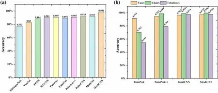
Fig.4 (Color online)Outline of the converting methods for 3D shapes.The X-axis indicates the proposed method,and the Y-axis indicates the classification accuracy
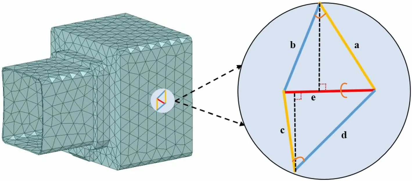
Fig. 5 (Color online) A convolution structure for edge irregular triangular meshes
• With respect to edge feature extraction, the features of each edge were carefully designed as a five-dimensional vector composed of the dihedral angle,two inner angles, and two edge-length ratios for each triangular patch. These features contain only relative geometric properties without absolute position information, and have invariance in rotation, scaling, and translation.Therefore, unlike common representations (such as point-based representations), features do not contain vertex coordinate information,which makes it better to generalize shape features and promote the invariance of the similarity transformation.
• Symmetric functions are designed to eliminate the fuzziness caused by the order of the edges, and the unique symmetry of the triangular mesh is used to eliminate the duality of the neighborhood order to make it invariant to translation, rotation, and scaling. The four edges are aggregated into two pairs of edges(a and c, b, and d) and a sum (b and d), and new features are generated by applying a simple symmetric function to each pair(abs(b,d)and sum(b,d)),which are then used for convolution.
3 MeshCNN-based brep to CSG conversion
3.1 Dataset generation for 3D CAD Model
Training datasets are crucial for deep learning. However,unlike images,it is difficult to create a dataset for 3D CAD models for four reasons. (1) The 3D CAD model is difficult to obtain and needs to be created manually,resulting in scarce availability of geometric datasets. (2)The more complex CAD model, which is generally represented by BREP, is unsuitable for most deep learning methods.It is difficult to convert CAD models into regularformat data. (3) Labels must be manually marked for the 3D-shape segmentation, and manual labeling cannot be extended. (4) In many cases, the semantics of the CAD model are unclear,and it is difficult to represent a 3D CAD model using semantic parts. Therefore, this study focused on how to easily generate datasets. The following section presents a dataset creation method for the CAD models commonly used in fusion reactors.
3.1.1 Labeling
A geometric processing pipeline was developed based on the OCC CAD engine, which was used to deal with CAD models to generate mesh,edge label,and weight files.Triangulation of the CAD model is a key step in the design of a model dataset. OCC provides a powerful mesh-generation algorithm that supports multiple CAD file formats(such as STEP, IGES, and STL) and includes various integrated mesh-generation algorithms. Defining a CAD model as having different semantic parts is difficult because semantics depend on the preferences of the modeler. Figure 6 shows an example of a labeled CAD model.Figure 6a is a representative CAD model in the dataset,defined as S. Figure 6b is the ideal result of segmentation according to the preferences of the modeler, defined as Spart, which is an abbreviation of semantic parts (marked as Seg1–6).Figure 6c shows the face list for each semantic part. Figure 6d shows a special semantic part in which faces are not used to guide the construction of auxiliary splitting surfaces.
The detailed labeling flow is shown in Fig. 7.
(a) Import a solid model S, traverse each face in S, and
obtain an ordered list of faces defined as Face_List.
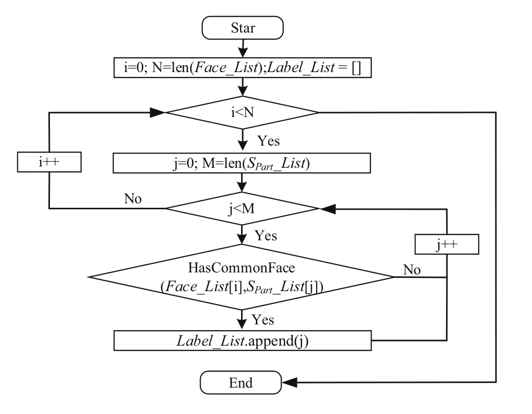
Fig. 7 Flowchart of model labeling
(b) Import the subbody model SPart, traverse each solid in SPart, and obtain an ordered solid list, defined as
SPart_List.
(c) If Face_list[i]is the same as the face in SPart_list[k],the label of Face_list[i] is set to k. If one face simultaneously belongs to more than one solid, the surface is marked as a special class, as shown in Fig. 6d.
(d) Finally, the label of each face in solid S is obtained and defined as Label_List.
3.1.2 Generation of a training dataset
The proposed algorithm was integrated into cosVMPT,which is widely applied in the fusion field. Therefore,typical fusion CAD engineering models were selected to generate a training dataset. A training dataset (Fig. 8)consisting of five typical types of fusion device models was constructed;some of the models are shown in Fig. 8.These models include the cryostat, TFC, VV, and TS. The generation process of the dataset is as follows:
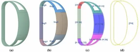
Fig.6 (Color online)A diagram of labeling.a An example of a CAD model being labeled.b The ideal segmentation result.c Face list of each semantic part. d A special semantic part

Fig. 8 (Color online) Typical models in the training dataset
(a) Model labeling Each model in Fig. 8 was labeled,as described in the previous section, and a label dictionary was obtained.
(b) Data augmentation The number of models was increased through rotation, scaling, and translation.The name of the generated model is the same as that of the basic model, and it is numbered successively.(c) Triangular meshing.
(d) Triangular patch labeling According to the model name (key), a label list for each face was obtained from the label dictionary and each triangular patch was labeled according to its affiliation with each face.
(e) Generating Training Files Mesh, edge label, and weight files were generated as training data for the MeshCNN.
3.2 Intelligent segmentation
This study also focused on a segmentation algorithm to achieve intelligent segmentation of a CAD model. The segmentation of a complete model requires the following processes (Fig. 9): (1) Import the CAD model to be converted. (2) Generate the corresponding mesh file. (3) Calltrained neural network for classification. (4) Export edge classification results of MeshCNN. (5) Modify theclassification results.(6)Obtain the classification results of the faces according to the affiliation relationship between the faces and edges and then group the faces according to the labels. (7) Generate auxiliary splitting surfaces based on the grouping results of the surfaces. (8) Segment the model using the generated splitting surfaces.
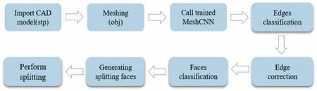
Fig. 9 Flowchart of a complete pre-segmentation
3.2.1 Edge correction
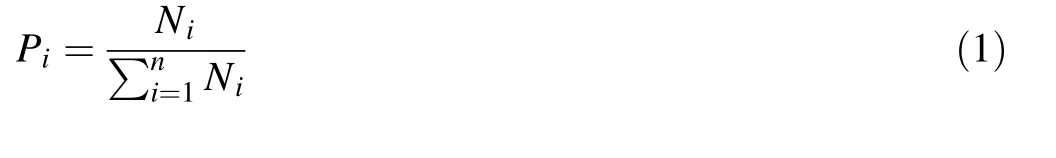
In many cases, some edges may be misclassified, as shown in Fig. 10a,which makes it difficult to generate split faces. However, the CAD models are rich in geometric information. Therefore, a strategy for edge correction was introduced to further improve the accuracy of edge classification. For each face, the category with the largest number was considered as the category of the face by counting the number of edges Ni of different types on each surface. Figure 10b shows the revised results.
3.2.2 Construction of common edge sets
The auxiliary splitting surface is constructed based on the edges of the model itself,and the classification result of each edge in the triangular patches cannot be directly used to generate an auxiliary splitting surface. Therefore, the first step in constructing an auxiliary splitting surface is to build common edges between the different segments (defined as Seg_List). The classification of each edge was obtained using MeshCNN, and the classification of each face was based on the affiliation relationship between faces and edges. Finally, faces with the same label were divided into segments, and a common edge set was generated by determining whether there were common edges between the segments. The implementation process is illustrated in Fig. 11.
3.2.3 Construction of auxiliary splitting faces
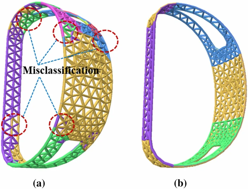
Fig. 10 (Color online) Classification results of edges using MeshCNN.a Classification results before correction. b Classification results after correction
Considering the different types of shared edges (e.g.,lines and arcs), the methods for generating auxiliary splitting faces also differ.It is necessary to limit the size of the splitting surface to avoid excessive segmentation of the model caused by the excessive size of the splitting surface,which can be achieved by limiting the endpoints of the common edges.According to the type of common edge,the following situations are considered in Fig. 12: (1) When the shared edges are an arc,a plane is constructed with the arc. (2) When the shared edges are two arcs, a cylindrical surface is constructed if the generatrix is parallel to the axis. A conical surface is constructed if the generatrix intersects the axis.(3)When a shared edge is a straight line,a plane is constructed using the straight line and the axis of its connected curved surface. (4) When the shared edges are two straight lines,two planes are constructed using the two straight lines and axis of the connected curved surface.(5) For other curves,a plane is constructed for each curve.
4 Verification and applications
4.1 Performance evaluation
To verify the feasibility and efficiency of the intelligent pre-segmentation algorithm, certain components (Fig. 13)of the latest 360-degree CFETR engineering model were employed. The main feature of these components is that they are composed of a large number of high-order surfaces(torus), which often require manual preprocessing before they can be correctly converted using cosVMPTs. Figure 14 shows the decomposition results of the traditional optimization algorithms and intelligent segmentation algorithms of a sector (22.5°) for the cryostat, TFC, VV,and TS. Figure 14d shows the decomposition results from cosVMPT for the intelligent pre-segmentation results and Fig. 14e shows the decomposition results of the original optimization algorithm. An outstanding advantage of
*Indicates models that cannot be converted correctly intelligent preprocessing is that the decomposed model is regular. Intelligent preprocessing prevents the generation of many thin sheets, which is the main reason for the failure of the OCC Boolean operation.
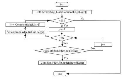
Fig. 11 Flowchart of constructing common edge sets

Fig. 12 Flowchart of the construction of auxiliary splitting faces

Fig. 13 (Color online) Some components of the latest 360-degree CFETR
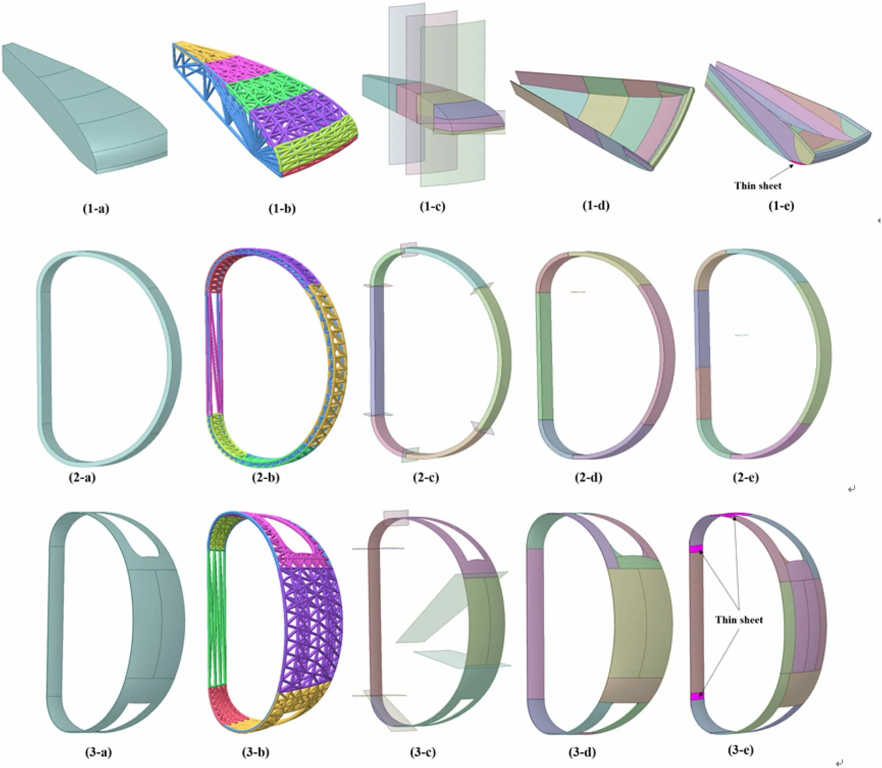
Fig. 14 (Color online) The decomposition results of traditional optimization and intelligent segmentation algorithms. a is the whole model to be converted, b is the classification result of triangular patches, c is the preliminary decomposition results of intelligent presegmentation using generated auxiliary splitting faces, d is the final decomposition results from cosVMPT for the pre-segmentation results, and e is the decomposition results of the traditional optimization algorithm
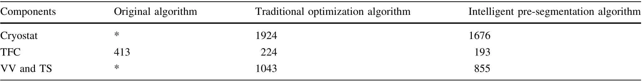
Table 1 Comparison of the final convex solids

Table 2 Comparison of the conversion CPU time
The quality of a conversion algorithm can be evaluated based on the number of final convex solids and the conversion CPU time.The more regular a model,the fewer the number of convex bodies, and the better the conversion algorithm. The presented algorithm was compared with other traditional algorithms based on cosVMPT [22].Tables 1 and 2 compare the final convex solids and conversion CPU times of the original conversion algorithm without optimization, the traditional rule-based optimization algorithm,and our deep learning-based intelligent presegmentation algorithm. The results show that the intelligent pre-segmentation algorithm exhibits a significant improvement in performance and efficiency,particularly in the conversion time. For VV and TS, which consist of a large number of toruses, the CPU conversion time was reduced by twice to thrice. Simultaneously, according to the evaluation of the experienced modeler, the conversion result was more intuitive and consistent with the intention of the modeler.
In many cases, tangential solids may be generated during the conversion. Because of accuracy, when a model is complex, it often leads to the loss of particles in tangent places.The modeler must pre-segment the model manually to avoid the generation of tangent solids, which is timeconsuming and tedious.Therefore,to reduce the generation of tangent solids, model datasets for local features, which often need to be handled manually, have been designed(e.g.,VV).Figure 15 presents some of the results.It can be observed that the segmentation result is more consistent with the modeler’s intention, and avoids the generation of tangent solids.
4.2 Robustness evaluation
To further verify the robustness of the intelligent presegmentation algorithm, test cases were designed, such as locally modifying the model, transforming the model(translation, rotation, and scaling), and using models with similar structures but different parameters. Figure 16 shows the validation results,illustrating that the intelligent pre-segmentation algorithm exhibited strong robustness and invariance in terms of rotation,translation,and scaling.The partial absence of a model does not affect the segmentation accuracy. When the model structure was significantly changed, as shown in Fig. 16f, the classification results were not ideal. On the one hand, triangular patches in a symmetrical position have the same attributes, the semantics are not obvious, and they are not easy to distinguish. On the other hand, a face may be recognized as two half faces by the OCC;therefore,the triangular patches will be different. This can be further improved through model repair techniques (e.g., merging surfaces) and by increasing the diversity of the training sets.In addition,the auxiliary surface-generation program can be further improved.
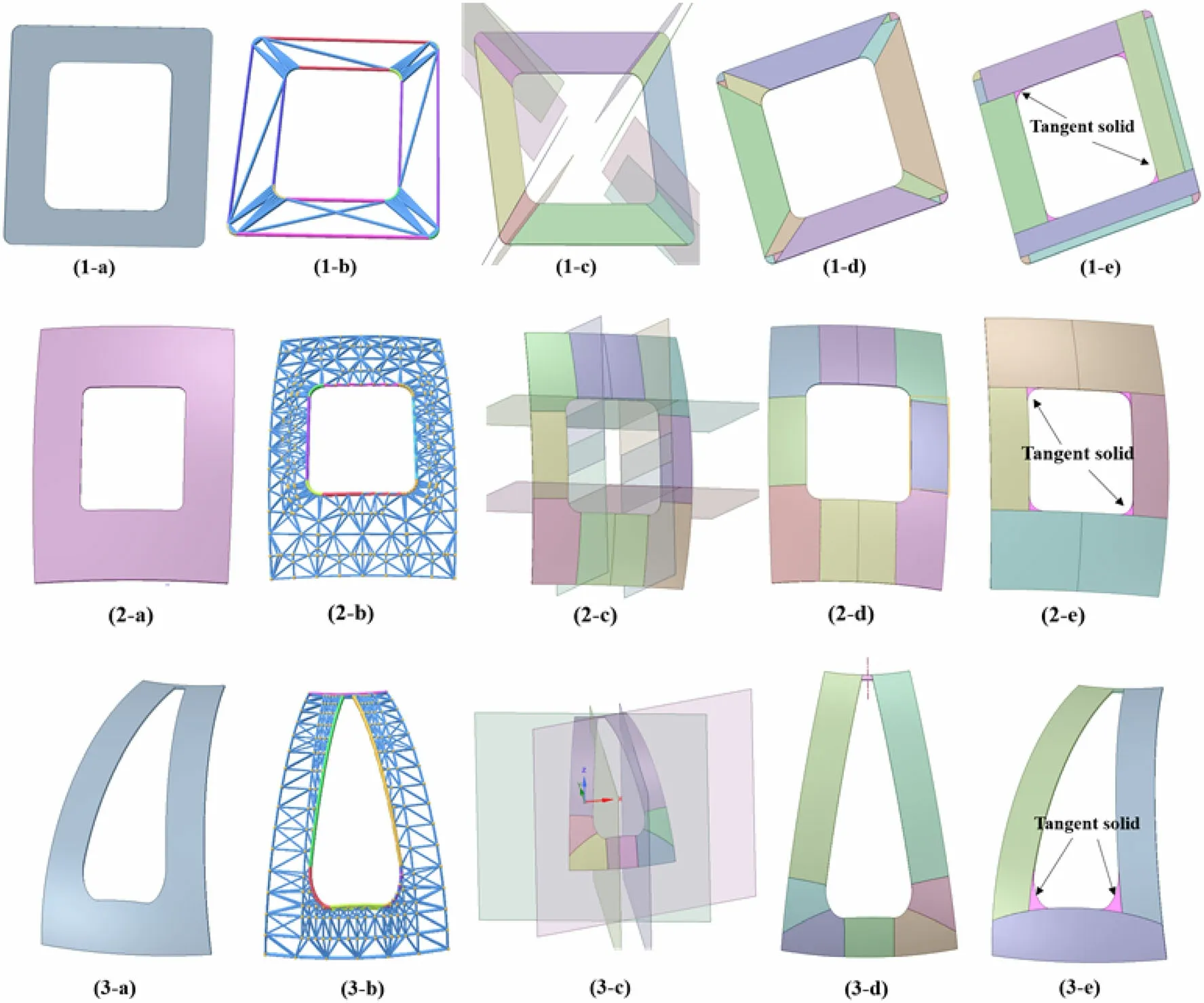
Fig. 15 (Color online) The decomposition results of traditional optimization and intelligent segmentation algorithms. a is the model part to be converted, b is the classification result of the triangular patches, c is the preliminary decomposition results of intelligent presegmentation using the generated auxiliary splitting faces, d is the final decomposition results from cosVMPT for the pre-segmentation results, and e is the decomposition results of the traditional optimization algorithm
5 Conclusion and prospects
Separation-based BREP-CSG conversion has the advantages of being efficient, reliable, and easy to implement.It is widely used in computer-aided modeling of MC codes. However, separation-based BREP-CSG conversion relies heavily on a large number of Boolean operations,which may fail in certain complex models.To improve the conversion efficiency and avoid errors, a 3D-shape segmentation algorithm based on MeshCNN was creatively applied to optimize the BREP-CSG conversion while avoiding manual intervention in the model preprocessing.The main contributions of this study can be summarized as follows. (1) A general labeling method for CAD models and a fast-training dataset generation method were implemented based on OCC. (2) Considering the CAD engineering models commonly used in fusion devices, five types of datasets were designed. (3) Intelligent pre-segmentation was validated using the representative components used in the CFETR. The results demonstrate that the intelligent pre-segmentation algorithm exhibits a significant improvement in performance and efficiency.The conversion CPU times of the VV and TS were reduced by two to three times. Moreover, the conversion result is more intuitive and consistent with the intention of the modeler, and avoids the generation of tangent solids. (4)The robustness of the intelligent pre-segmentation algorithm was verified. Clearly, the intelligent pre-segmentation algorithm exhibited strong robustness and invariance in terms of rotation, translation, and scaling.
Training models are very important for the proposed algorithm, and it is not currently easy to prepare a large training model. Therefore, it is necessary to develop a visual interactive model labeling method in which a model can be marked according to the intention of the modeler to clarify semantic information (such as triangular patches in a symmetrical position) in future. Because the proposed algorithm is a learning-based method, it is suitable for areas with multiple components of similar shape, such as the fusion reactor and reactor core, which are major application areas of related software (such as cosVMPT,MCAM, and McCad).

Fig.16 (Color online)Robustness test of the intelligent segmentation algorithms.a Translation.b Rotation.c Scaling.d Filling.e Holing.f With a similar structure but with different parameters
Author contributions All authors contributed to the study conception and design. Material preparation, data collection and analysis were performed by Yue-Tong Luo, Hua Du, and Yi-Man Yan. The first draft of the manuscript was written by Hua Du, and all authors commented on previous versions of the manuscript. All authors read and approved the final manuscript.
杂志排行

Nuclear Science and Techniques的其它文章
- The role of deformations and orientations in an alpha ternary fission of Thorium
- Feedforward compensation of the insertion devices effects in the SSRF storage ring
- A new radar stealth design excited by 210Po and 242Cm
- Development of an ultrafast detector and demonstration of its oscillographic application
- Low-radioactivity ultrasonic hydrophone used in positioning system for Jiangmen Underground Neutrino Observatory
- Study on analytical noise propagation in convolutional neural network methods used in computed tomography imaging