Investigation on the seismic response of nuclear power stations with a pile-raft foundation using centrifuge tests
2022-07-12LiZhongchengYangYangGongWeimingYiPikChengDaiGuoliangandLiangFayun
Li Zhongcheng, Yang Yang, Gong Weiming, Yi Pik Cheng, Dai Guoliang and Liang Fayun
1.State Key Laboratory of Nuclear Power Safety Monitoring Technology and Equipment, China General Nuclear Power Corporation, Shenzhen 518029, China
2.Key Laboratory of Concrete and Prestressed Concrete Structures of Ministry of Education, Southeast University,Nanjing 211189, China
3.Department of Civil, Environmental and Geomatic Engineering, University College London, London, UK
4.Department of Geotechnical Engineering, Tongji University, Shanghai 200092, China
Abstract: Research to reliably predict the seismic response of nuclear power stations with a pile-raft foundation is needed to meet the high safety requirements of nuclear power stations.In this study, a scaled superstructure with a 4×3 pile-raft foundation, which is constructed in Shanxi kaolin clay, is modelled.Accordingly, the characteristics of seismic response for nuclear power stations with a pile-raft foundation are analyzed using dynamic centrifuge tests.In particular, multiple earthquake motions with different magnitudes and frequency properties are utilized to map the relationship between structural response and properties of earthquake motions.The results show that the seismic response of the soil, raft, and structure are significantly affected by the natural frequency and magnitude of the earthquake motion.The soil surface acceleration is lower than the raft acceleration.The results provide a reliable reference to better understand the seismic response of nuclear power stations.
Keywords: dynamic centrifuge test; seismic response; pile-raft foundation; nuclear power station; soil-structure interaction
1 Introduction
Pile foundations have been widely utilized in soft soil areas for many modern structural systems,including buildings, bridges, offshore wind farms, and railway foundations (Chenet al., 2011; Katzenbachet al., 2016; Wuet al., 2017; Zhouet al., 2016).As more sophisticated theoretical and experimental research into pile foundations has been carried out, the recognition of raft contribution to the performance of pile foundations has gained acceptance (Bhaduri and Choudhury, 2020;Clancy and Randolph, 1993; Nguyenet al., 2013;Poulos, 2001; Royet al., 2018).Considering the state of construction technology development for nuclear power stations and site limitations, only a few such stations have been built around non-rock areas, such as the Clinton, Grand Gulf, River Bend, and Callaway nuclear power stations in the USA.Moreover, no such project has been constructed in China around soft soil areas.The current requirement for nuclear power station sites is that the foundation should rest on firm shallow rock layers (NB/T 20308-2014: design code for nuclear safety-related plant foundation for pressure water reactor nuclear power plants).However, the number of sites that satisfy this requirement is limited, and there are other considerations in the decision-making process for the location of nuclear stations.There is little published research on the seismic response of nuclear power stations located in soft soil areas with a pile-raft foundation.Considering the catastrophic loss of life and property to society as caused by earthquakes (Ohnishi,2012), research on the seismic response of such nuclear power stations is urgent.
A pile-raft foundation under earthquake loads is subject to two different forces: inertial forces from the superstructure and ground deformations induced by the seismic load.The dynamic response of the structural system are influenced by ground motion amplification,stiffness differences between the foundation and the soil,and stiffness degradation (Avilés and Pérez-Rocha, 1998;Biet al., 2011; Duttaet al., 2005; Ghosh and Madabhushi,2007; Kim and Roesset, 2004; Moghaddasiet al., 2011;Sgarlatoet al., 2011), which significantly increases the complexity of the problem.When designing pile-raft foundations, the soil, foundation, and superstructure should be considered as an integrated structural system(Boulangeret al., 1999; Royet al., 2020; Sahaet al.,2015); however, the calculation method is not provided in related codes.After earthquakes in Mexico City in 1985,Northridge in 1994, and Kobe in 1995, post-seismic observations have pushed research focus towards soilstructure interaction (SSI) effects.Understanding the SSI characteristic seismic response of nuclear power stations with pile-raft foundations in soft soil is critical to ensure their safe operation.
The dynamic centrifuge test is a useful tool to study the seismic response of structures while considering the SSI effect.However, sands are typically used instead of clays (Baziaret al., 2018; Sawada and Takemura, 2014;Wilsonet al., 2000; Yooet al., 2017).A single pilestructure system was studied without considering the pile group effect (Boulangeret al., 1999), and a shallow foundation (but not a pile foundation) was used (Ghosh and Madabhushi, 2007; Trombettaet al., 2013).Also, the structure loads were usually simplified as a mass block(Banerjeeet al., 2014; Hussienet al., 2016; Lianget al.,2020; Zhanget al., 2017).For nuclear power stations,the dynamic centrifuge model cannot be oversimplified due to the associated safety requirements.
In this study, the seismic response of a nuclear power station was examined using dynamic centrifuge model tests with a 50 g gravity level.The scaled superstructure with a 4×3 pile-raft foundation was constructed in Shanxi kaolin clay and subjected to different earthquake shaking types and magnitudes.The soil, raft, and structural accelerations, the pore water pressure of the clay soil, the bending moment of typical piles, the container′s horizontal displacement, and the structure′s displacements were recorded.The seismic response of nuclear power stations with an emphasis on the structural acceleration and pile bending moment are reported herein.This research provides a reference to understand the seismic response of nuclear power stations.
2 Dynamic centrifuge test set-up
The dynamic centrifuge tests were performed at Tongji University using a TLJ-150 geotechnical centrifuge (Lianget al., 2020), as shown in Fig.1.The frequency of the excitation ranged from 20 to 200 Hz.The maximum dynamic centrifuge acceleration is 50 g,and the maximum shaking duration under the maximum acceleration is 1 s.The laminar shear model box is shown in Fig.2.
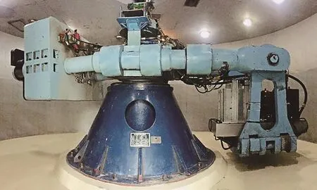
Fig.1 Photograph of the TLJ-150 geotechnical centrifuge
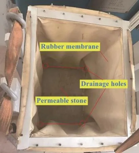
Fig.2 Photograph of the laminar shear model box
2.1 Dynamic centrifuge model
The nuclear power station model was designed according to the third-generation nuclear power station in China.Due to the limited capability of the centrifuge shaking table, the prototype dimension of the scaled model in the tests is about 10 times smaller than the practical project structure.Note that the dimensions of the structure and test results in this study are presented for the prototype unless otherwise stated.The superstructure mainly includes a containment structure for the nuclear reactor (cylinder and dome) and a cuboid annex for the reactor, and the corresponding model is shown in Fig.3.The scaling laws for the dynamic centrifuge testing are illustrated in Table 1 (Ghoshet al., 2007).The properties of the model and prototype are summarized in Table 2.The length, width, height, and thickness of the cuboid are 11.05 m, 8.20 m, 3.70 m, and 0.05 m, respectively.The reactor can be divided into two parts, including the cylinder and dome.In particular, the height, diameter,and thickness of the cylinder are 6.09 m, 5.40 m, and 0.1 m,respectively.The height and thickness of the dome are 1.12 m and 1.25 m, respectively.In addition, the cuboid of the model is made of polymethyl methacrylate(PMMA) with a density of 1.18 g/cm³.The material of the raft and cylinder is aluminium.The dome is made of iron with a density of 7.8×10³kg/m3.
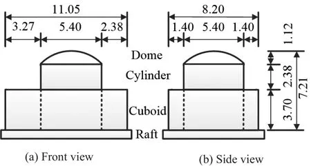
Fig.3 Schematic of the superstructure model (Unit: m)
The length, width, and height of the internal space in the laminar shear model box utilized in the test are 25 m,20 m, and 27.5 m, respectively.The box consists of 22 high-strength hollow aluminium rings (each with a height of 1.25 m).Also, an inside rubber membrane, which is used to minimize the effects of boundary reflections, is mounted on the internal surface of the aluminium rings.Hence, the boundary effect of the box is negligible(Yanget al., 2019).In addition, four drainage holes at the bottom corner are covered with permeable stones,as shown in Fig.2.The drainage holes create a doublesided drainage consolidation environment.
The model and corresponding sensor layout are shown in Fig.4.The length, width, and height of the raft are 11.9 m, 9.05 m, and 0.8 m, respectively, and the distance between the raft edge and the external cuboid edge is 0.43 m.The length, diameter, and thickness ofthe tube pile are 15 m, 0.7 m, and 0.05 m, respectively.The tube pile is made of aluminium with a density of 2.7 g/cm³.The properties of the piles are shown in Table 3, compared with the piles in three previous studies(Boulangeret al., 1999; Yanget al., 2019; Zhanget al.,2017).Note that the test results in these studies are also presented in the following paragraphs.
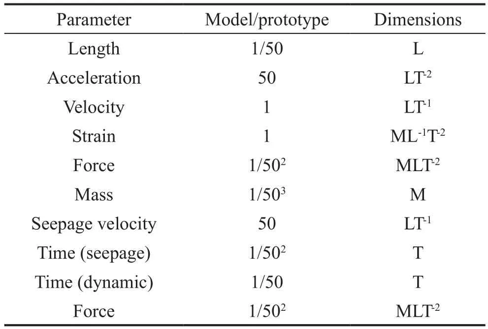
Table 1 Scaling laws for the dynamic centrifuge testing
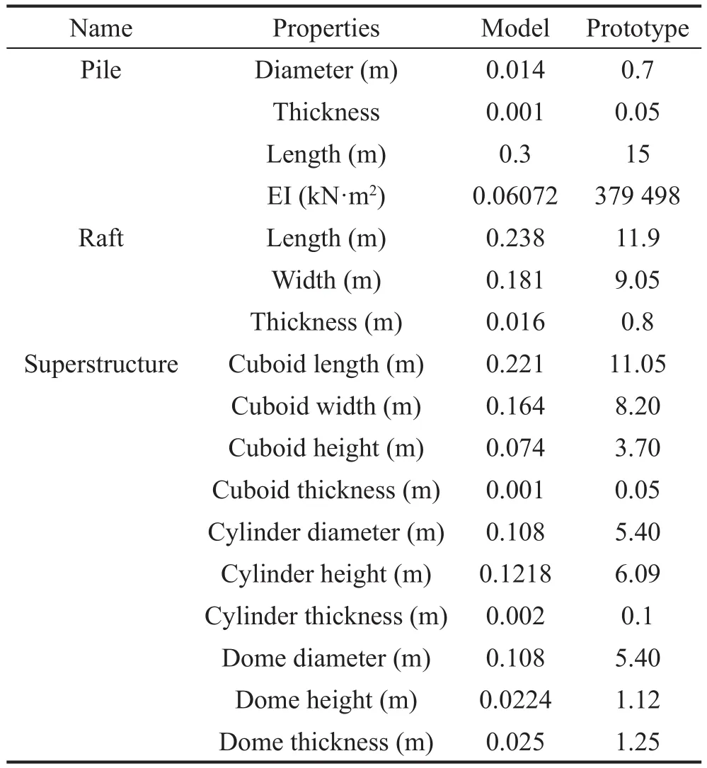
Table 2 Properties of the model and prototype

Table 3 Properties of the piles used in this and previous studies
As shown in Fig.4, the clay depth at Shanxi kaolin is 17.5 m.Under the clay, there is a 2.5 m thick sand layer that acted as a filter layer.The shaking direction is along the short edge (width) of the raft, and the model has axial symmetry.There were 12 piles in this work that were rigidly fixed to the raft using bolts with a pile spacing of 2.24 m, which is three times the pile diameter.Three piles, named P-1, P-2, and P-3, in the pile-raft foundation were equipped with four full-bridge strain gauges to determine the bending moment of the piles.The relationship between the strain and bending moment in each sensor position of the piles was calibrated via step-by-step loading based on a cantilever beam.Four accelerometers were arranged at various locations andutilized to measure the seismic acceleration of the soil at depths of 20 m (A4) and 1 m (A3) and at the raft (A2)and structure (A1).Note that recorded data via A4 and A3 were the input motion and soil surface acceleration,respectively.Six displacement transformers (LS1-LS3 and DS1-DS3) were used to scan the time history of the model displacement and the soil box.The LS1 and LS2 were equipped at different sides of the structure,measuring the settlement and inclination.LS1 and LS2 were placed near the edge of the structure at a distance of 1.25 m apart.The LS3 was installed to measure the horizontal displacement of the structure under seismic loading.Three differential displacement meters were equipped along the shaking direction at the side of the laminar shear model box to measure the horizontal displacement of the soil under seismic loading at the 7th,11th and 16th high-strength hollow aluminium rings.
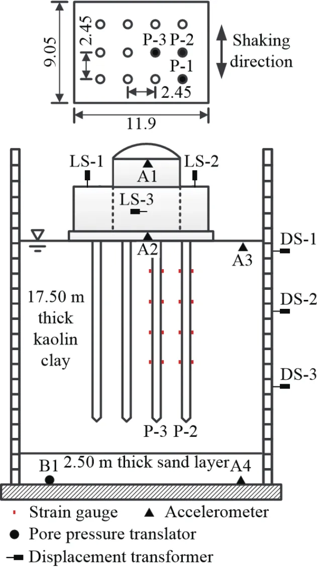
Fig.4 Schematic of the model set-up and sensor locations
A sand layer with a thickness of 2.5 m was first paved into the base of the model box.The sand used at the bottom of the box was Fujian standard sand with diameters ranging from 0.5 mm to 1 mm.The filter paper was then paved on the surface of the sand, above which the kaolin clay was poured.The clay beds used in the centrifuge model tests were prepared using Shanxi kaolin powder.The kaolin clay powder and water mixture (2:1)were subjected to 24 h of preloading under 1 g conditions with double drainage.There were four drainage holes at the perimeter connected with internal permeable stone at the bottom.This configuration is beneficial to implement double-sided drainage consolidation for soft clay.Lastly,another filter layer was placed on the surface of the kaolin clay, and 25 kg of sand was loaded on the filter.The sand corresponded to effective overburden stress of approximately 1.23 kPa at the top of the clay mixture.
The box was loaded onto the shaking table of the centrifuge to perform centrifuge consolidation under a 50 g gravity field to develop the required strength profile and stress history under double-sided drainage conditions.To accurately control this process, a laser displacement sensor was applied to measure the soil surface settlement, while a pore water pressure sensor(B1) monitored the dissipation of the excess pore water in the soil.After 20 h, the soil settlement rate was reduced, and the pore water pressure tended to stabilize;thus, the centrifuge consolidation was considered to be complete.The top sand layer and filter paper were removed after in-flight centrifuge consolidation of the clay was completed.The basic properties of the Shanxi kaolin clay used in this study are shown in Table 4.The water content was tested after the dynamic centrifuge tests were completed.
2.2 Ground motion
The dynamic centrifuge tests were performed with three ground motions and white noise.The ground motions used in the tests included two natural earthquake waves and an artificial seismic wave.In particular, the 1940 El Centro wave (EL) and 1985 Mexico City wave(MEX) are the two selected natural earthquake waves.The YG seismic wave is an artificial seismic wave based on the EUR soft design response spectrum, in case the model is built in a soft area.According to the centrifuge test scaling ratio and the excitation frequency (20 Hz to 200 Hz) of the shaker, the earthquake waves are scaled in time and amplitude using a Butterworth bandpass filter.
The acceleration and Fourier amplitude of the selected earthquake waves with a peak acceleration of 0.1 g is shown in Fig.5.The duration and predominant period of the YG wave are 25 s and 0.35 s (corresponding predominant frequency, 2.88 Hz), respectively.The duration of the EL wave and MEX wave is 50 s.However,the predominant periods of the EL wave and MEX wave are 0.41 s (corresponding predominant frequency, 2.43 Hz)and 2.22 s (corresponding predominant frequency,0.45 Hz), respectively.The EL wave and MEX wave represent short period and long period ground motions,respectively.The white noise excitation is conducted at the beginning of the tests with frequency ranging from 20 Hz to 200 Hz to determine the dynamic characteristics of the test model using the transfer function.
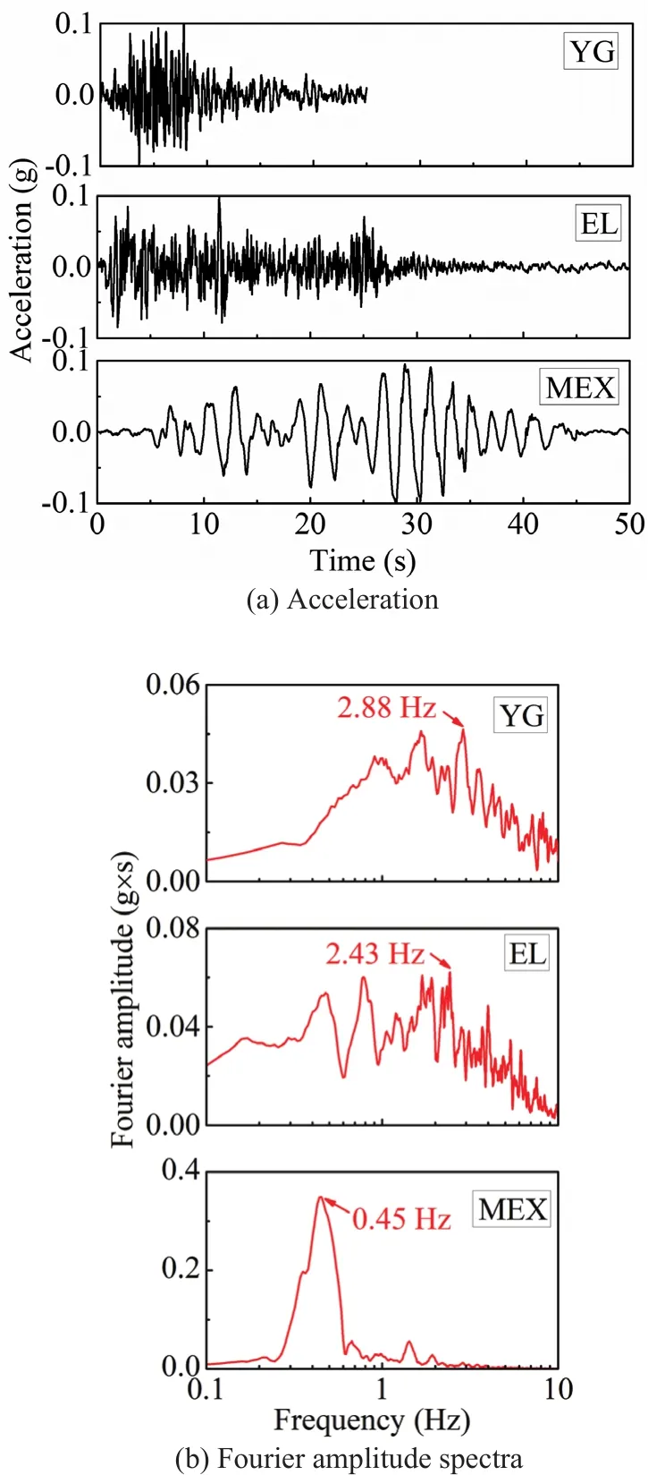
Fig.5 Input seismic waves used in dynamic centrifuge tests
2.3 Test schedule
Three ground motions, including the YG, EL, and MEX, and a white noise are adopted as input excitation.The YG and EL are applied at three magnitudes, including 0.1 g, 0.2 g, and 0.3 g.In addition, the magnitudes of the MEX and white noise are 0.1 g and 0.05 g, respectively.
The actual acceleration acting on the shaking table significantly depends on the methods of wave generation,mainly including the peak ground acceleration-based method (PGA-based method) and energy-control method.The energy-control method, which controls the energy of the input excitation, is utilized in this study.An accelerometer, A4, is mounted on the shaking table, torecord the actual excitation.Eight test cases are illustrated in Table 5.Theαmaxis the designed magnitude of input ground motions, and theAmaxrepresents the actual magnitude of the input excitation, which is recorded by the accelerometer, A4.The main test procedures for the dynamic centrifuge tests are described as follows.
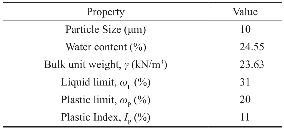
Table 4 Basic properties of the Shanxi kaolin clay used in this study

Table 5 Dynamic centrifuge program
(i) The strain gauges are mounted on the piles and connected to the data acquisition system using the full-bridge circuit.The gauge wires are placed in the tubular pile through a pre-punched hole.Two different protection types of glue, including silica gel and epoxy resin,are used to make the structure waterproof.Afterward,the strain gauges are connected to the data acquisition system using the gauge wires.
(ⅱ) The soil sample is paved into the box.After consolidation of the soil sample, the box is mounted on the shaking table to determine the best operating voltage for all input motions.The operating voltage for the driver is determined based on the correlation between the input signal and the output acceleration.
(ⅲ) The positioning device is established to ensure the installation accuracy of piles.
(ⅳ) The displacement transformers and acceleration sensors are mounted on the raft and structure.Afterward,the box, in which the test model and soil sample are installed, is mounted on the shaking table.
(v) Based on the best operating voltage, the dynamic centrifuge tests with different excitations are conducted in an orderly way.
3 Test results and discussion
3.1 Dynamic characteristics of the model
The seismic response of the model under white noise excitation was first studied to analyze its dynamic characteristics.The time history acceleration and Fourier amplitude spectra under white noise excitation are shown in Fig.6.Time history acceleration curves at the soil depth of 20 m and 1 m of the raft foundation and the structure are shown in Fig.6(a).The maximum acceleration of the soil during the tests at a depth of 20 m (input motion) and 1 m (soil surface) and at the raft and structure were 0.07 g, 0.08 g, 0.08 g and 0.10 g,respectively, as shown in Fig.6(a).The objective input motion magnitude was 0.05 g; however, the practical input motion recorded by A4 at the depth of 20 m was 0.07 g.Figure 6(b) shows the Fourier amplitude spectra of the acceleration for this test.The low-frequency component is distributed over most of the frequency ranges.The dominant frequencies for the soil at a depthof 20 m and the soil at a depth of 1m are 3.45 Hz and 1.20 Hz, respectively, and the peak values for the raft and structure are 1.20 Hz and 2.70 Hz, respectively.There are two peak values, as illustrated in Fig.6(b) for the structure, 1.21 Hz, and 2.70 Hz.The seismic response of the structure and the raft are different.
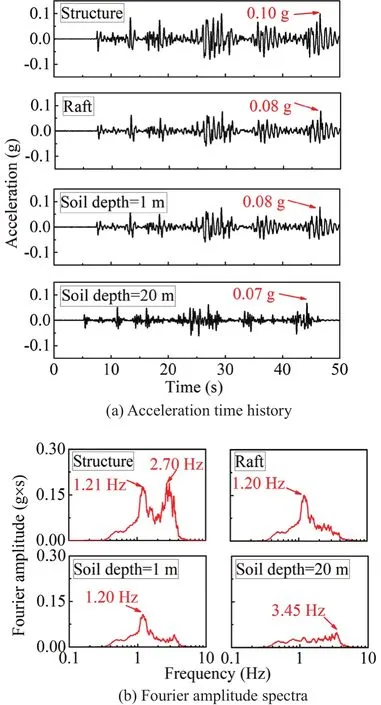
Fig.6 Measured acceleration under white noise excitation
Since the Fourier spectra of the shaking table acceleration isF(w) and that of the raft, structure, and soil at a depth of 1 m isG(w), the transfer functionH(w)of the raft, structure and soil acceleration is given byH(w)=G(w)/F(w) (Lianget al., 2019).As shown in Fig.7, the transfer functionsH(w) of the surface soil and the raft are similar, showing one dominant peak at 1.31 Hz and a secondary peak at 2.84 Hz in each transfer function.The dominant peak frequency for the structure is smaller at 1.29 Hz.In addition, there is no secondary peak at the high-frequency range, which is due to the dynamic characteristics of the superstructure.
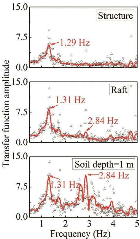
Fig.7 Transfer function under white noise excitation
3.2 Influence of input motion and peak base acceleration on the response of soil and structure
After white noise excitation, seven other tests were performed independently, as shown in Table 5.Figure 8 shows the recorded acceleration and the Fourier spectra under 0.1 g, 0.2 g, and 0.3 g YG wave excitations.Under 0.1 g YG wave excitation, the maximum acceleration at a soil depth of 20 m (input motion), at the soil depth of 1 m, the raft and structure were 0.15 g, 0.13 g, 0.24 g,and 0.38 g, respectively, as shown in Fig.8(a).The dominant frequencies at those locations were 1.73 Hz,0.98 Hz, 1.69 Hz, and 1.71 Hz, as shown in Fig.8(b).The dominant frequency at the surface of the soil (soil depth=1 m) was lower than that at the soil depth of 20 m.This implied that the high-frequency of the input motion was depressed, and the low-frequency component was enlarged.The same characteristic was shown with 0.2 g and 0.3 g YG wave excitation, as shown in Figs.8(c)to 8(f).Figures 9 and 10 show the recorded acceleration and Fourier spectra under the EL and MEX excitations,respectively.
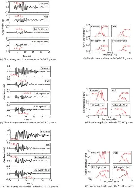
Fig.8 Acceleration under YG wave excitation
The peak accelerations of input motion, soil surface,raft, and structure are shown in Figs.8 to 10 for each of the seven tests.These comparisons are summarized in Fig.11.The peak acceleration of soil surface, raft,and structure increased with the increase of input motion magnitude.The response of the structure and raft under the YG excitation was weaker than that under the EL excitation.For example, under 0.2 g YG wave and EL wave excitation, the peak accelerations of the structure were 0.40 g and 0.47 g, respectively.The peak acceleration of soil surface, raft, and structure response were strongly affected by the frequency content of the earthquake motion (i.e., YG versus EL) as well as by the level of shaking.The frequency content of the earthquakes is illustrated in Fig.5, which shows the Fourier amplitude spectra for the base input motions with the same peak accelerations.The YG input motions had smaller spectral accelerations than the EL input motions in the frequency range from 1 to 3 Hz.This was the main reason why the soil, raft, and structural models under YG excitation responded less strongly than the EL excitation.
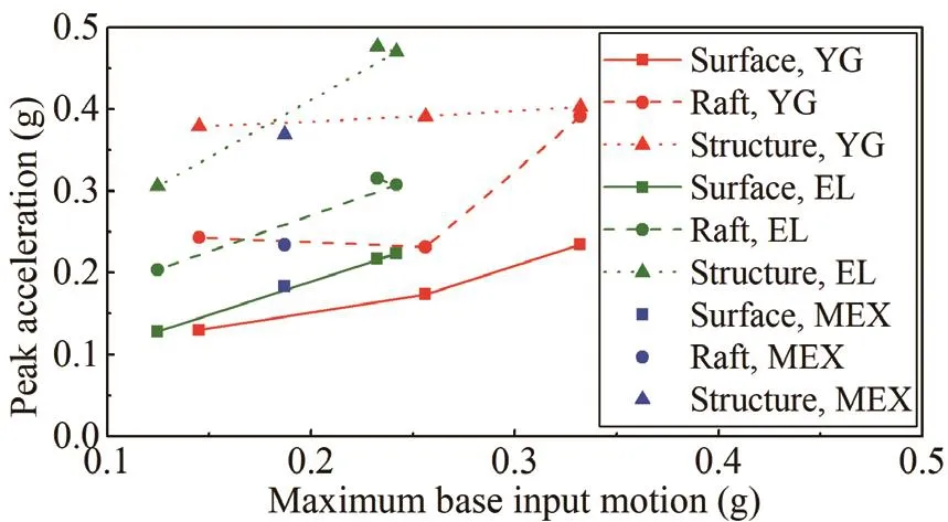
Fig.11 Peak superstructure acceleration
The peak accelerations of the soil surface, raft, and structure over the peak acceleration of the input motionswere calculated to determine the amplification ratios,as shown in Fig.12.The amplification ratios generally decrease with a more significant base peak acceleration.This trend is consistent with the expected effects of nonlinearity for the ranges of structural periods, soil profile periods, and input frequency content for these tests.As seen from the results of the YG-0.1 g, YG-0.2 g, and YG-0.3 g cases, the amplification ratios of the structure are 2.61, 1.53, and 1.21, respectively.The same principle is generated for the EL-0.1 g, EL-0.2 g,and EL-0.3 g cases.Similar results were obtained from the previous research (Boulangeret al., 1999; Lianget al., 2017; Liuet al., 2018).However, the results were in contrast with the previous findings (Ghosh andMadabhushi, 2007), which concluded that using the free surface motion as the foundation input motion in design could be a conservative approximation in many soil profiles with a similar layering.The acceleration of the raft, in this study, was higher than that on the soil surface, because the raft bears the load transferred from the foundation and the inertial forces from the structure under dynamic loads.
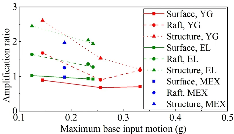
Fig.12 Amplification ratio for the peak acceleration
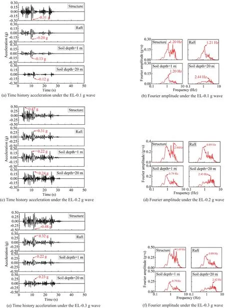
Fig.9 Acceleration under EL wave excitation
3.3 Influence of soil depth and input motion on the horizontal displacement of soil
Three displacement meters, DS-1, DS-2, and DS-3 were located on the side of the laminar shear model box at the 7th, 11th, and 16th high-strength hollow aluminium rings.The soil depth at the 7th, 11th, and 16th rings are 1 m, 5.8 m, and 11.8 m, respectively.Therecorded horizontal displacements of the soil under the YG wave, the EL wave, and the MEX wave excitations are shown in Fig.13.The maximum horizontal displacements for each earthquake excitation obtained from Fig.13 are summarized in Table 6 and Fig.14.The horizontal displacement of the soil at a deeper depth had a more significant horizontal displacement due to the reduction effect of clay.For example, under the YG-0.1 g excitation, the peak horizontal displacement of the soil at the depth of 1 m, 5.8 m, and 11.8 m were 35.33 mm, 48.09 mm, and 64.71 mm, respectively.This amplifying characteristic was the same for all the other cases and was caused by the properties of the clay.The peak horizontal displacement of the soil increased with the increase of the magnitude of earthquake waves.The peak horizontal displacement of the soil under the MEX wave was the largest at comparable input magnitudes.This may be because a dominant frequency (1.31 Hz)generated from the transfer function of the soil at the depth of 1 m is, as shown in Fig.8, closer to the second dominant frequency (1.42 Hz) of the input MEX waves,as shown in Fig.10(b), which induces a resonance effect.
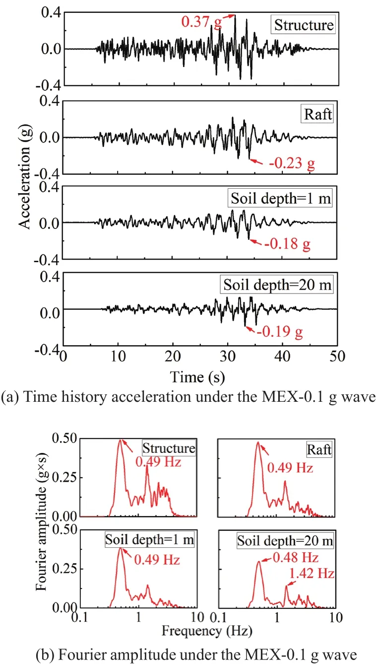
Fig.10 Acceleration under MEX wave excitation

Fig.13 Horizontal displacement of soil for each of the considered excitation waves
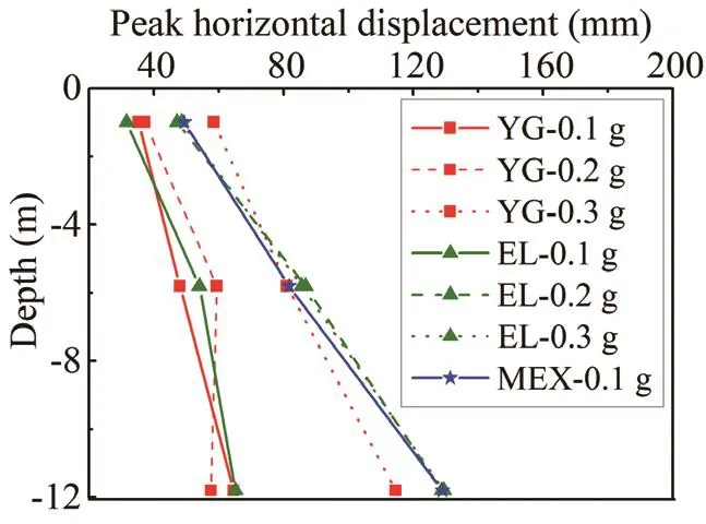
Fig.14 Peak horizontal displacement of soil
3.4 Influence of input motion and peak base acceleration on the excess pore water pressure
A piezometer was located at the bottom of the box to record the excess pore water pressure of the soil under the earthquake wave excitation.The original pore water pressure was zero as caused by the reset operation of the acquisition system, so the recorded pore water pressure data by the piezometer was the excess pore water pressure.
Figure 15 shows the excess pore water pressure under all considered earthquake wave excitations.Figure 15(a)shows the excess water pressure under the YG wave excitations, including 0.1 g, 0.2 g, and 0.3 g.The excess pore water pressure increased with the increase of input motion magnitude.The same characteristic was shown in Fig.15(b) under the EL wave excitation.Note that the instant peak excess pore water pressure under the EL-0.2 g case was higher than that under the EL-0.3 g case due to the practical input motion peak acceleration for the EL-0.2 g case and EL-0.3 g case were 0.24 g and 0.23 g, respectively.For the MEX-0.1 g case, the excess pore water pressure was higher than the comparable magnitude of input motion, which was induced by the resonance effect as mentioned, as shown in Fig.15(c).After shaking, the pore water pressure appeared to remain stable, implying that much more time was required to reduce the excess pore water pressure for larger acceleration magnitudes.
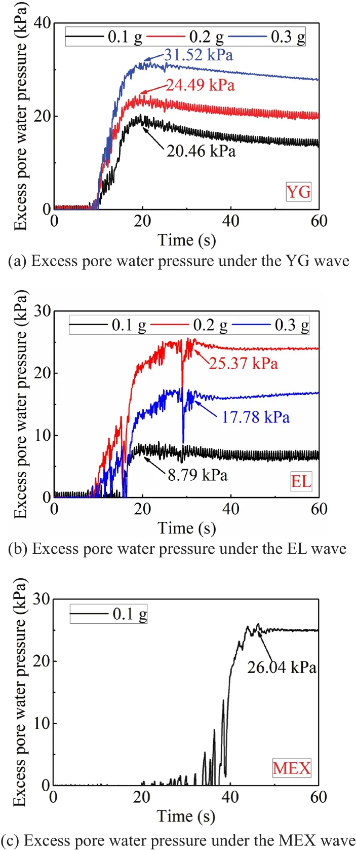
Fig.15 Excess pore water pressures under all considered earthquake wave excitations
Figure 16 shows the relationship between peak instant pore water pressure and the magnitude of input motion.The peak excess pore water pressure increases with the acceleration magnitude.
3.5 Influence of input motion on the movement of the structure
Under earthquake excitation, the inertial forces generated in the superstructure cause it to rock.This creates horizontal displacements in the structure alongwith vertical displacements.Three displacement sensors,including LS1, LS2, and LS3, were equipped in the test model to monitor the movement of the structure.
For monitoring the vertical displacements, LS1 and LS2 were located at the long edge of the structure with a distance of 9.40 m, as shown in Fig.4.Table 7 shows the vertical displacement and inclination of structure.The vertical displacement at different sides (LS1, LS2)differs due to the rocking, suggesting one side of the foundation has settlement while the other side possibly generates an uplift problem (Hokmabadi and Fatahi,2016).The maximum average values of LS1 and LS2 is 3.35 mm.Dividing the difference vertical displacement between LS1 and LS2 by their distance 9.4 m obtains the inclination value, which was utilized to analyze the inclination of the structure, as shown in Table 7.All the incline data for the nuclear power station were acceptable.
To monitor the horizontal displacement of the structure, a displacement sensor LS3 was equipped at the side of the structure model, as shown in Fig.4.The cuboid,made from PMMA, is soft generating vibration of itself,which results in an error in the horizontal displacement of the structure during earthquake excitation.The residual horizontal displacement after shaking was utilized to analyze the horizontal displacement of the structure.The residual horizontal displacements include the horizontal displacement of the soil and the absolute displacement of the structure.The residual horizontal displacement is shown in Table 8.Note that the residual displacement under the MEX-0.1 g earthquake loads is 26.57 mm,which is the largest due to the resonance effect.The horizontal displacement for the YG cases is lower than the EL cases.For example, under the YG-0.3 g case andthe EL-0.3 g case, the horizontal displacements of the structure are 13.58 mm and 25.11 mm, respectively.
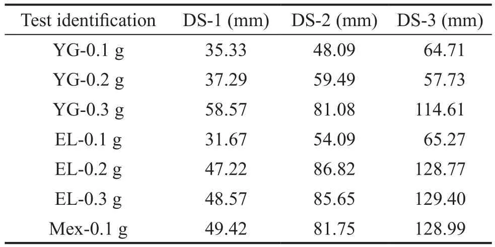
Table 6 Peak horizontal displacement of soils
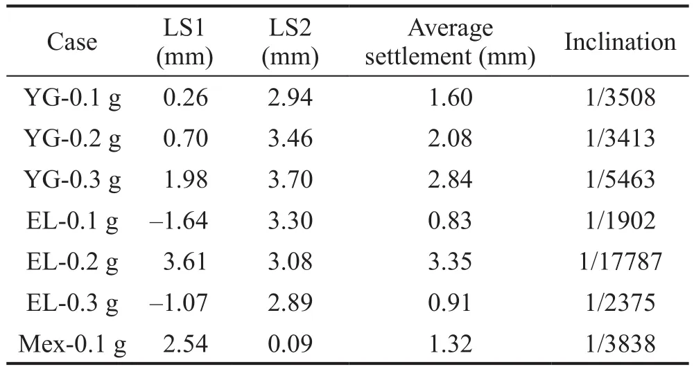
Table 7 Vertical displacement and inclination of structure
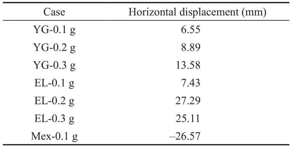
Table 8 Horizontal displacement of structure
3.6 Influence of input motion and pile location on the bending moment of the pile
As shown in Fig.4, three piles (P-1, P-2, and P-3)were equipped with strain gauges to determine the bending moment of the piles.The distance between the first strain gauge and the pile head (bottom of the raft)was 2.5 m.The other three strain gauges were located at the pile depth of 5.0 m, 7.5 m, and 10.0 m, respectively.
The dynamic bending moments of pile P-2 under different seismic wave loads are shown in Figs.17 to 19,respectively.The peak positive and negative moments are labelled in those figures.Note that the maximum bending moment is an average of the positive and negative peak bending moments.The values recorded at a pile depth of 2.5 m is the maximum along with the pile.This is to endure the tremendous inertial forces transformed from the superstructure.The frequencies corresponding to the dominant peak of the piles at a 2.5 m depth for the YG-0.1 g, EL-0.1 g, and MEX-0.1 g are 0.27, 1.21, and 0.51 Hz, respectively.The vibration characteristics of the superstructure under different earthquake excitations may cause the dominant peak variety of pile bending moment.Figure 19 shows the pile bending moment under the MEX-0.1 g case, which is different from that under the YG case.During the excitations, the lowfrequency MEX wave induced a resonance with the foundation, which caused the bending moments of the piles to increase distinctly.
The pile bending moments for P-2 under the 0.3 g seismic waves were studied, as shown in Figs.20 and 21.The increased wave energy carried under a 0.3 g magnitude caused the maximum Fourier amplitude of pile 2 at a depth of 2.5 m under YG-0.3 g and EL-0.3 g to occur at 0.91 Hz and 0.82 Hz, respectively.The Fourier amplitudes for the same pile decreased at greater depths,as shown in Figs.17 to 21.This was thought to be caused by a decreased pile bending moment with greater depths.
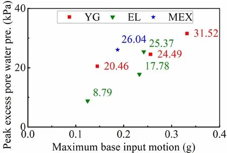
Fig.16 Peak instant excess pore water pressure
To better understand the bending moment of the piles at different depths and locations, the maximum bending moments were determined from the recorded time history bending moment data.Figure 22 shows the maximum bending moment for all piles (P-1, P-2, and P-3).The maximum bending moment decreases with depth and is located primarily at the depth of the 2.5 m.The bending moment of P-2 and P-1 is higher than P-3 because they absorb more earthquake energy and act as a shield for P-3 in the second row.Figure 23 shows the maximum bending moment of the pile at the depth of 2.5 m under different cases.The bending moment for P-3 decreases rapidly compared with the other two piles.The bending moment increases with the input acceleration magnitude, such as for the YG seismic waves at 0.1 g,0.2 g, and 0.3 g accelerations showing increasing recorded bending moments.Note that the maximum pile bending moment at 2.5 m depth under the MEX seismic load is larger than the other seismic loads under the same acceleration magnitude, which is due to the resonance effect.
The amplification or decreased ratio of the maximum pile bending moment was calculated by the ratio of the bending moment of the pile heads.P1, P2, and P3 represent the bending moment of the pile head for piles located at the corner, at the edge of the second row, and the inner position of the second row, respectively.Figure 24 shows the amplification ratio of the maximum pile bending moment of P1/P2.Three research results areshown in Fig.24, including the results from this study and the previous research results (Yanget al., 2019;Zhanget al., 2017).Earthquake events 1-6 represent different tests carried out by the researchers.The amplification ratio for pile 1 over pile 2 is approximately 1.5.Attention must be given to ensure the stiffness of the corner piles since they bear more inertial force transferred from the superstructure and kinematic forces.The decrease ratio in the previous research (Yanget al.,2019) was slightly higher than that in this study.This may be due to the different pile diameter, spacing, and PGA.For conservative reasons, the decrease ratio can be taken as 0.8.The amplification ratio and decrease ratio are only suitable for estimating the bending moment in dynamic centrifuge tests and more research is needed toobtain these ratios for use in practice.This study provides evidence that reinforces the adoption of reduced stiffness for the design of the inner piles, which offers a financial benefit to such construction projects.
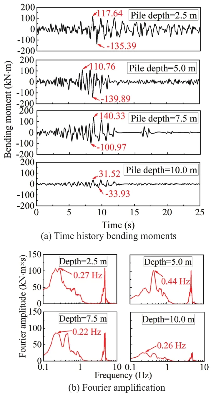
Fig.17 Bending moment of pile 2 under YG-0.1 g wave excitation
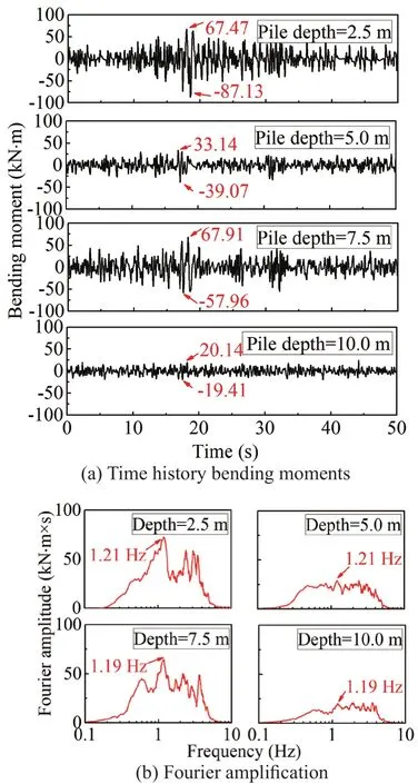
Fig.18 Bending moment for pile 2 under EL-0.1 g wave excitation
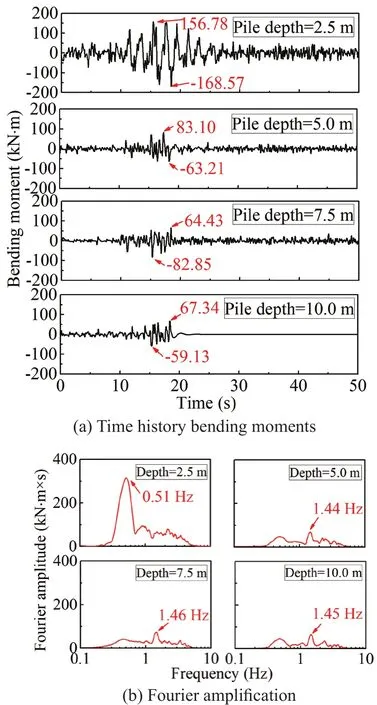
Fig.19 Bending moment for pile 2 under MEX wave excitation
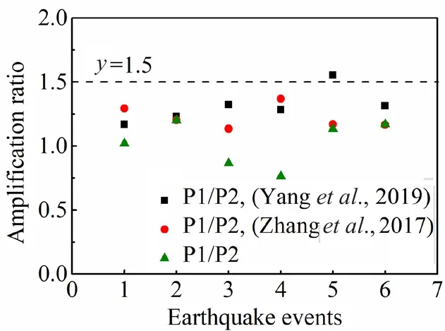
Fig.24 Ratio of maximum pile bending moment for P1/P2
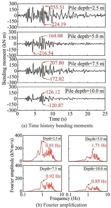
Fig.20 Bending moment for pile 2 under YG-0.3 g excitation
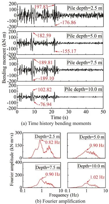
Fig.21 Bending moment for pile 2 under EL-0.3 g wave excitation

Fig.22 Maximum bending moment for all piles
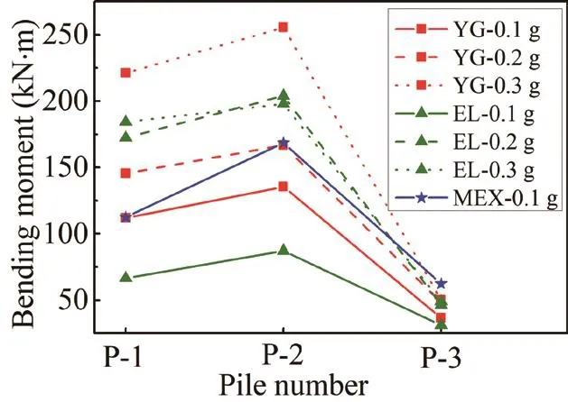
Fig.23 Maximum bending moment of the pile at depth of 2.5 m
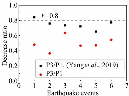
Fig.25 Ratio of maximum pile bending moment for P3/P1
4 Conclusions
In this study, the results of a series of dynamic centrifuge model tests for a nuclear power station on Shanxi kaolin clay, considering the SSI effect, were presented.The following conclusions can be drawn from this study.
(1) The soil acceleration, raft acceleration, and structural acceleration were magnified by various degrees under different intensity excitation.The seismic response of the soil, raft, and structure were strongly affected by the frequency content of the earthquake motion.With the increase of peak base acceleration, the acceleration amplification ratio generally decreased.In the structure design process, the foundation input motion could be different from the soil surface acceleration.The soil near-surface acceleration was lower than the raft acceleration based on the recorded data in this study.
(2) The horizontal displacement of the soil was higher when the frequency of the input motion was in line with the natural frequency of the soil.The instantaneous excess pore water pressure increased with the acceleration magnitude, and more time was required to reduce the excess pore water pressure at larger acceleration magnitudes.Considering the SSI effect, the inertial forces generated from the superstructure resulted in a rocking motion of the structure under earthquake loads, which induced a horizontal displacement of the structure and an uneven soil settlement.Moreover, the pile-raft foundation could endure soil settlement with an acceptable inclination of the raft.
(3) The Fourier amplitudes for the same pile decreased with the depth.At greater depths, the bending moment of the piles decreased but was the largest at the pile head.The first row of the pile group absorbed more earthquake energy and acted as a shield for piles in the second row.This study reinforces the adoption of reduced stiffness for the design of inner piles.
Acknowledgment
The authors gratefully acknowledge the support from the Scientific Research Program of China General Nuclear Power Corporation (CGN) (Grant No.K-A2017.054) and Postgraduate Research and Practice Innovation Program of Jiangsu Province (Grant No.KYCX19_0093).
杂志排行
Earthquake Engineering and Engineering Vibration的其它文章
- Property estimation of free-field sand in 1-g shaking table tests
- Dynamic p-y curves for vertical and batter pile groups in liquefied sand
- Underground blast effects on structural pounding
- An analytical model for evaluating the dynamic response of a tunnel embedded in layered foundation soil with different saturations
- Controlled rocking pile foundation system with replaceable bar fuses for seismic resilience
- Seismic ground amplification induced by box-shaped tunnels
