Controlled rocking pile foundation system with replaceable bar fuses for seismic resilience
2022-07-12ChengZhaoLiShuaiandWangJingquan
Cheng Zhao, Li Shuai and Wang Jingquan
Bridge Engineering Research Center of Southeast University, School of Civil Engineering, Southeast University,Nanjing 210096, China
Abstract: Bridges designed following a conventional approach minimize the risk of collapse, but often require challenging, costly, and time-consuming restoration after an earthquake occurs.The new seismic design philosophy requires bridges to maintain functionality even after severe earthquakes.In this context, this paper proposes a controlled rocking pile foundation (CRPF) system and numerically evaluates bridges′ degree of seismic resilience.The CRPF system allows a pile cap to rock on a pile foundation and dissipate seismic energy through inelastic deformations of replaceable bar fuses that connect a pile cap and piles.Following the conceptual design of the CRPF system, two analytical models were developed for a bridge pier utilizing the CRPF system and a pier designed to develop a plastic hinge in its column.The analytical results indicate that, after experiencing a severe earthquake, a conventionally designed bridge pier sustained substantial damage in its column and exhibited significant residual displacement.In contrast, a pier using the CRPF system showed negligible residual displacement and maintained elastic behavior except, as expected, for bar fuses.The damaged fuses can be rapidly replaced to recover bridge seismic resistance following an earthquake.Therefore, the CRPF system helps to achieve the desired postearthquake performance objectives.
Keywords: seismic resilience; bridges pier; controlled rocking; pile foundation; repairable bar fuse
1 Introduction
A conventional seismic design relies on the formation of plastic hinges in preselected locations to dissipate seismic energy and protect bridges from collapse.Although bridges designed in this manner are generally considered to provide adequate safety, they often sustain excessive damage and exhibit considerable residual drifts following a significant seismic event.Damaged bridges can disrupt traffic, necessitate time-consuming inspections, and may be difficult and financially prohibitive to repair.Hence, new design strategies and technologies are required to achieve additional seismic performance objectives, such as mitigating economic losses, maintaining bridge functionality, and improving repairability.
Structures with a rocking mechanism offer the potential to achieve the aforementioned seismic performance objectives.Housner (1963) first showed that structures that survived the 1960 Chile earthquake because they rocked on their foundations or on the underlying soil.Even experiencing a large deformation for the duration of shaking, rocking structures can suffer less damage and re-center after a high-intensity earthquake.Housner (1963), Meek (1975), Chopra and Yim (1985), Acikgoz and DeJong (2012), and Kalliontziset al.(2016) investigated the rocking dynamic of free rocking structures, which rely on structural weight to resist an overturning moment and minimize residual drift.Recognizing that free rocking structures may experience excessive deformation during an earthquake,numerous efforts have been made to develop controlled rocking structures, which utilize post-tension and/or supplement energy dissipating devices to control rocking responses.Priestleyet al.(1999), Restrepo and Rahman (2007), and Sritharanet al.(2015) developed unbonded post-tensioned precast rocking walls with additional hysteretic energy dissipaters, in which the prestressing tendons at the center of the wall panels provided the re-centering force.The concept of central post-tensioning has been extended to bridge columns(Hewes and Priestley, 2002; Chou and Chen, 2006;Restrepoet al., 2011).Precast columns with internal,unbonded, prestressing tendons were designed to rock at their base.Additional hysteretic energy-dissipatingcapacity was provided by internal partially debonded longitudinal bars that cross the rocking interface (Wanget al., 2008; Ouet al., 2010; Roh and Reinhorn, 2010)or external attached energy dissipaters (Marriottet al.,2009; Guoet al., 2015).Mitoulis and Rodriguez (2017)developed a novel resilient hinge that can be placed at the column base.This allows the column to rock and provides re-centering and energy dissipating capabilities through replaceable steel rebars that connect the top cover and bottom bearing plate of the hinge.
Utilizing the weight of the superstructure as a recentering force, the bridge column supported on a shallow foundation would mobilize rocking behavior without post-tensioning.Mergos and Kawashima (2005)and Denget al.(2012) numerically studied the seismic response of bridges with rocking shallow foundations by using the nonlinear Winkler-foundation model.Saiidiet al.(2002), Espinoza and Mahin (2008), and Antonelliset al.(2015) conducted shake table tests to study the response of bridge columns supported on rocking shallow foundations.These studies revealed the merits of the rocking shallow foundation (such as re-centering capacity, significant energy dissipation, and well-defined capacity).However, the concerns of this type of system,such as relatively low bearing capacity, residual drift due to the permanent deformation of underlying soils,and the difficulty of effecting repairs following an earthquake, still need to be addressed (Gajan and Kutter,2008; Allmond and Kutter, 2014).Titiralet al.(2017)and Releet al.(2019) combined a pile foundation with a rocking shallow foundation, and placed elastomeric pads between them.The seismic resilience of this system was validated through a numerical approach.Several studies have demonstrated that the foundations supported on the unattached piles (i.e., no tension is transferred from the pile caps to the piles) could affect the rocking mechanism at the foundations while having a lesser amount of concern about soil conditions.Allmond and Kutter(2012; 2013) conducted centrifuge tests to explore the behavior of a rocking foundation on unattached piles.Antonellis and Panagiotou (2014) numerically analyzed bridges that have rocking pile foundations and which were subjected to earthquake ground motions.Guanet al.(2018) tested a large-scale pile foundation model with a rocking pile cap, providing evidence with regard to the feasibility of employing the rocking pile foundation.
In order to complement the rocking systems and facilitate their application in bridge construction, a new controlled rocking pile foundation (CRPF) system is introduced in this paper.The CRPF system extends the concept of rocking pile foundation and uses replaceable bar fuses that connect the pile cap to the piles.When subjected to strong ground shaking, the pile cap rocks on the piles and the fuses dissipate seismic energy by undergoing inelastic deformation.Therefore,the system is capable of controlling maximum drift during an earthquake, preventing significant structural damage while minimizing residual drift.Following an earthquake event, bridges can immediately open to regular use, because the structural components that transfer service loads experience little or no damage.A bridge′s seismic resistance can be rapidly recovered by replacing any deformed fuses.Moreover, the CRPF system is suitable for implementing prefabricated technologies, thus offering additional benefits such as reduced on-site construction time, minimized mobility and environmental impacts, improved product quality,and more (Culmo, 2011).This paper presents the CRPF system in detail and validates its seismic resilience through a numerical approach.The outcomes of this study will provide guidance for future experimental studies.
2 Rocking mechanism of the CRPF system
A CRPF system consists of piles, a precast pile cap,and buckling-resisting bar fuses that connect the piles and pile cap.Shallow sockets are pre-formed on the bottom of the precast pile cap, and the piles are placed into these sockets.The sockets are made slightly larger than the pile heads, so there is some spacing around the pile heads.An experimental study (Guanet al., 2018)confirmed that the detail of leaving spacing in the sockets successfully allowed for the uplift and rocking of the pile cap, and made the pile heads work like dowels to prevent the pile cap from significant slipping with respect to pile foundation.Figure 1 illustrates the rocking mechanism of the CRPF system during a loading cycle in terms of lateral load (F) versus column drift (Δ).The behavior of the fuse is also expressed by using the relationship between fuse axial force (Ff) and fuse elongation (Δf).For the duration of loading, the CRPF system first experiences a small elastic deformation.As the lateral load reaches the decompression force (Fd), the piles underneath one side of the pile cap are decompressed (Fig.1(a)).Then the pile cap starts to lift from the decompressed piles while the sockets transfer lateral forces from the pile cap to piles on the opposite side.Consequently, the fuses that connect to the decompressed piles are stretched in tension.These fuses will remain elastic until the force in the fuses reaches their yield value (Ff,y) (Fig.1(b)).As pile cap uplift increases, the fuses undergo plastic deformation and dissipate energy.The yielding of the fuses causes a softening of the system response.Thus,the column experiences a large drift without a significant increase in lateral load resistance (Fig.1(c)).As the pile cap significantly enlarges the base size, the CRPF system is characterized by its low overall slenderness ratio, and the location of the center of gravity would not exceed the point of support even for a large drift.As a consequence,the P-delta effects transform the structural weight to the source of restoring force, thus producing re-centering capacity for the CRPF system.During the unloading,the decrease in the pile cap uplift leads to compressive yielding in the fuses (Fig.1(d)).The superstructure weight (W) eventually re-centers the system.As the pilecap sets back to the piles, the fuses are subjected to zero deformation and develop residual compressive stress(Fig.1(e)).It is worthwhile to note that, even though the P-delta effect provides re-centering capacity for the CRPF system, this effect induces a secondary bending moment along the height of the column, which needs to be properly addressed in the design.
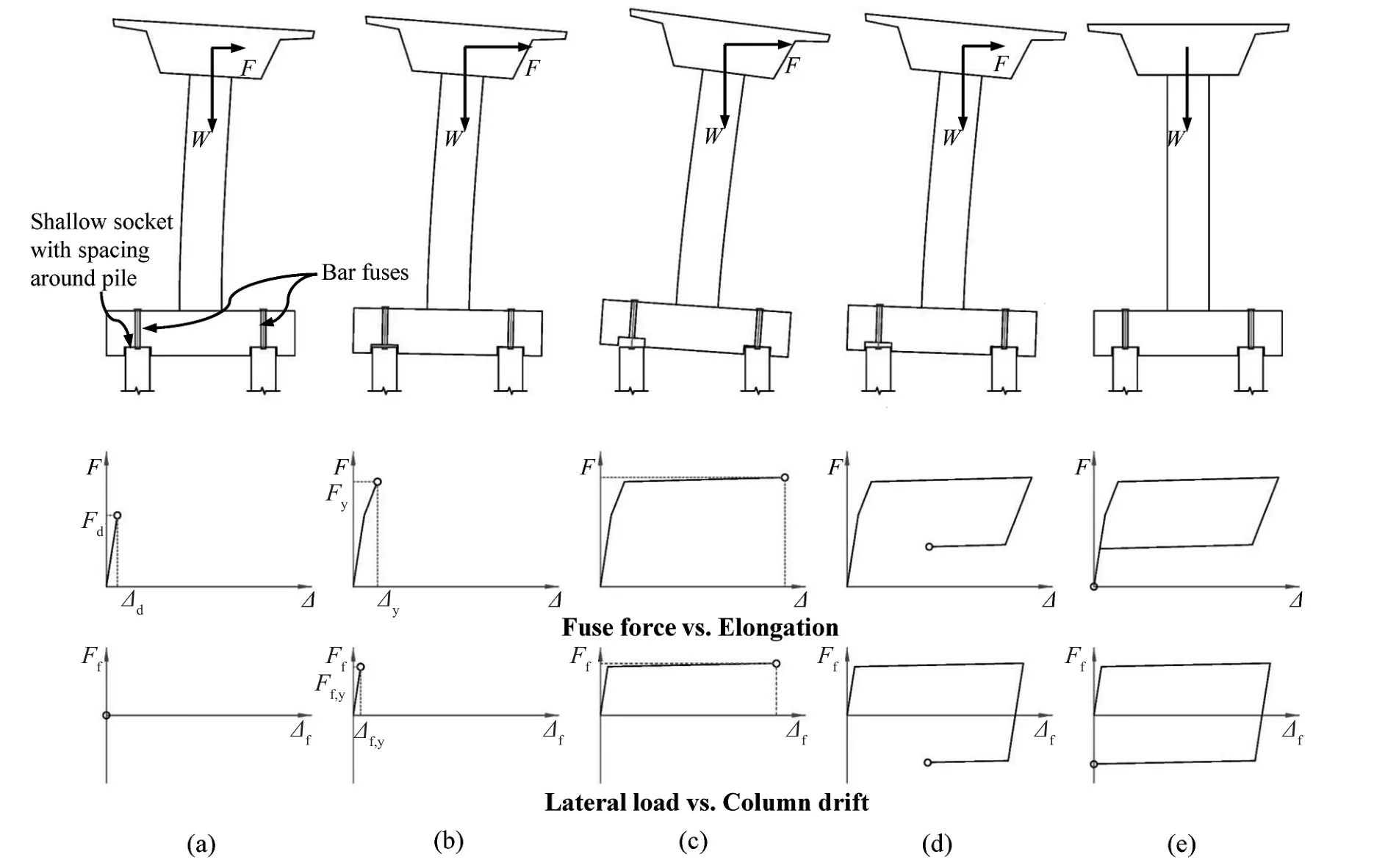
Fig.1 Rocking mechanism of the CRPF system: (a) pile decompression; (b) fuse tensile yielding; (c) fuse plastic elongation; (d) fuse compressive yielding; and (e) re-centering
3 Conceptual design of the CRPF system
A bar fuse is the essential component that enables the CRPF system to dissipate seismic energy.For ease of installation and replacement, it is preferred to fasten the fuses using screw threads.After evaluating different types of fuses, the groove type buckling-resisting bar fuse (White, 2014) is identified to be appropriate for the CRPF system.As shown in Fig.2(a), this type of fuse features a mild steel bar with several grooves milled along its length, a steel confining tube placed over the grooved bar, and the end connection regions are manufactured with threads.The grooves create a reduced cross-section area for achieving the fuse action.The confining tube prevents the fuse from buckling in compression, thus ensuring that the fuse dissipates seismic energy through both tensile and compressive yielding.The loading tests conducted by White (2014)demonstrated the energy dissipation capability of the groove type bar fuse.When subjected to cyclic tensioncompression forces, the force-elongation response of the fuse is found to follow the kinematic hardening rule,as shown in Fig.2(b), whereAf=the area of the fuse region of the mild steel bar,Ff=force in the bar fuse,fy=yield strength of bar steel,fu=tensile strength of bar steel,Lf=the length of the fuse region of the mild steel bar,εy=yield strain of bar steel,εu=ultimate strain capacity of bar steel, andΔf=elongation of the bar fuse.For mild steel used as an energy dissipation component,the PRESSS design handbook (Pampaninet al., 2010)specifies strain limits of 0.7εufor the ultimate limit state(ULS) and 0.9εufor the maximum considered earthquake(MCE).Prestressing is considered to be introduced to the bar fuses.By this means, an additional lateral force is required to stretch the fuses to yield, and the fuses will reach their ultimate strain at a smaller drift.Given that the CRPF system can achieve the design lateral force demand by using an appropriate fuse area and pile spacing, the prestressing in the fuses is thus not pursued because high drift ductility is desired for the CRPF system.
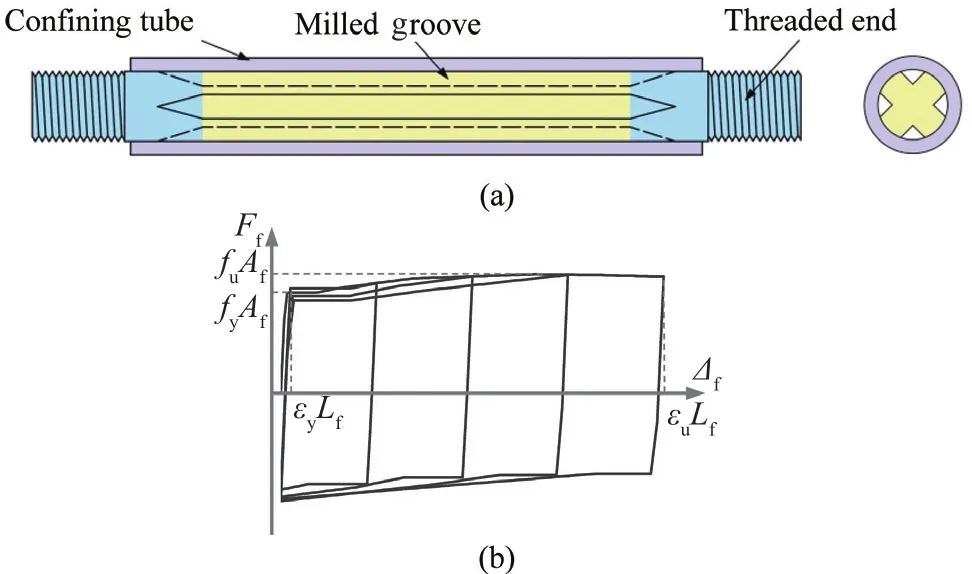
Fig.2 (a) Configuration (White, 2014) and (b) force-elongation response of the bar fuse
The CRPF system can be constructed on different types of pile foundations, including the bored pile or the driven pile.A cast-in-place (CIP) concrete pile head is constructed over the pile to embed the threaded splicing couplers that fasten the fuses.This detail also ensures that the pile head precisely fits the pre-formed sockets.Figure 3 illustrates the possible details of the pile head for different types of piles.For all these details, the steeltube serves as the stay-in-place formwork and provides confinement to protect the pile head from local damage.As shown in Fig.3(a), the longitudinal reinforcements of the bored piles extend into the CIP pile head to splice the pile head to the bored pile.For steel H-piles, a slot is cut on the web of the pile to allow the splicing coupler to be placed.The force from the coupler is transferred to the pile through the shear studs welded on the pile(Fig.3(b)) or by directly welding the coupler to the pile by using mending plates (Fig.3(c)).Figure 3(d) shows the pile head details for steel pipe piles.Slots provide access to weld the shear studs inside the pipe, which are used to transfer the coupler force to the pile.For the concrete driven piles (Fig.3(e)), the splicing couplers can be anchored in the hole reserved on the pile top.In order to provide full contact between the pile head and pile cap, the pile cap is placed on the piles immediately after pouring concrete into the steel tube.Prior to the concrete reaching sufficient strength, the weight of the pile cap can be temporarily carried by (1) temporary supports; (2) the steel H-pile; (3) the steel pipe pile; or(4) supporting bolts embedded in or screwed into the reserved holes on the concrete pile, depending on the type of pile.
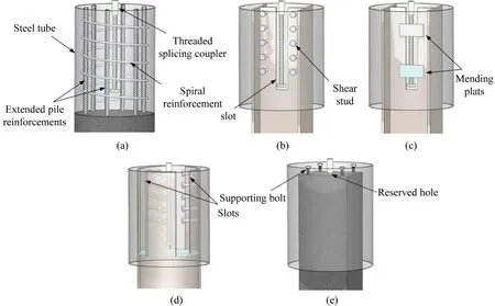
Fig.3 Pile head details for (a) bored pile; (b) steel H-pile with shear studs; (c) steel H-pile with wielded mending plates; (d) steel pipe pile; (e) driven concrete pile
As shown in Fig.4, bar fuses pass through vertical voids that are created in the precast pile cap and are screwed into the threaded splicing couplers embedded in the pile heads.Protective coatings can be applied to the fuses, and the anti-buckling tubes can consist of stainless steel.Such corrosion-resistant methods enhance the durability of the fuses.To allow the fuse to yield in tension and compression, “pinned” connections are required to fasten the fuses to the pile cap.Figure 4 shows two possible connection details, namely, the threaded pipe connection and plate nut connection.The threaded pipe connection has an embedded pipe made with external and internal threads on the top portion of the void.The external threads ensure that the pipe is sufficiently anchored in the pile cap, and the internal threads are designed to fasten the threaded insert.The fuse passes through the hole at the center of the threaded insert.Two nuts on the top and bottom of the threaded insert fasten the fuse to the insert.The protecting cap prevents corrosion in the pipe, insert,and nuts.Alternatively, the plate nut connection screws a plate nut to the fuse.A cap plate is bolted to the pile cap using threaded rods embedded in the pile cap.The platenut bears on the pile cap, and the cap plate compresses the plate nut, thereby fastening the top of the fuse to the pile cap.Each of these two types of connections are detachable.Therefore, following an earthquake, the fuses can be disconnected with the pile cap and screwed off from the piles for inspection and replacement.In case long fuses are required, the pile cap can be made with protrusions (Fig.5) to accommodate the fuses without a significant increase in the thickness of the pile cap.For ease of construction, the pile cap can be precast and placed above the soil surface, which eliminates on-site formwork, large volume concrete pours, and backfilling.On-site construction can be further simplified by using a precast column with a socket connection, as proposed by Cheng and Sritharan (2019, 2020).
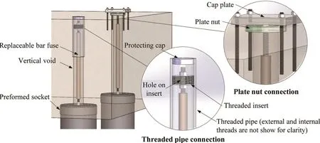
Fig.4 Connections fastening the fuse to the pile cap
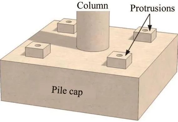
Fig.5 Pile cap with protrusions
The CRPF system can be designed following a simple procedure according to its rocking mechanism.For a certain lateral force demand and target drift ratio,this procedure determines the required area and length of the bar fuses.This procedure is generally suitable for different seismic levels by using lateral force demand and target drift ratio corresponding to the design earthquake.Because the CRPF system can be designed to have a comparable stiffness and damping ratio with conventional bridge piers, the lateral force demand and target drift ratio for different design earthquakes can be determined by following current design practice.As illustrated in Fig.6(a), for the CRPF pier, the lateral force that decompresses the pile,Fd, can be approximated as follows:

whereP=total axial load on the pile group,N=total number of piles in the pile group,Ni=the number of piles in theith row,di=the distance from theith row to the exterior row,L=column height, andDpc=the depth of the pile cap.
The bar fuses provide additional resistance to allow the CRPF pier to reach the target lateral force capacity.As illustrated in Fig.6(b), for a design lateral force,Fy,the required fuse area for each pile,Af, can be determined by using the following equation:

whereni=the number of fuses in theith row.
For design purposes, the drift of the CRPF pier is conservatively assumed to result from an uplift of the pile cap only (Fig.6(b)), even though the column would experience a small elastic deformation.Therefore, to achieve sufficient elongation to accomplish the design drift ratio, the required length of the bar fuse,Lf, can be determined as follows:

Fig.6 Design of the CRPF pier: (a) decompression force and (b) area and length of the bar fuses

whereθ=the target drift ratio anddp=the distance between the exterior rows.
4 Numerical verification for seismic response
The seismic response of the CRPF system was investigated by using the numerical approach.Two bridgepiers were analyzed, one with a single column supported on the CRPF system (CRPF pier) and the other similar in geometry to the CRPF pier but designed to form a flexural plastic hinge at the column base (PH pier).The three-dimensional numerical models of the CRPF and PH piers were developed and subjected to static cyclic loads, dynamic free vibrations, and earthquake ground motions, respectively.The response of the CRPF pier was compared with that of the PH pier.
4.1 Description of the PH and CRPF Piers
The PH and CRPF piers were designed and detailed for a prototype bridge that was hypothetically located at a site with a peak ground acceleration of 0.8 g, in accordance with Caltrans Seismic Design Criteria(Caltrans, 2019).The site is classified as C for an average un-drained shear strength of 120 kPa (2500 psf)for the upper 30 m (100 ft) of the soil profile.The bridge configuration is depicted in Fig.7(a).The superstructure consists of two 37.0 m (120 ft)-long, precast box girders,which were simply supported at the pier.The pier column was 11.0 m (36 ft) tall and had a circular crosssection with diameters of 1.8 m (6 ft).All components of the pier were designed for the use of concrete, with a specified compressive strength of 28 MPa (4 ksi)and reinforcing steel conforming to ASTM A706M(A706), with a specified yield strength of 420 MPa(60 ksi).The bar fuses in the CRPF pier consisted of ASTM A572M (A572) steel bars with a specified yield strength of 345 MPa (50 ksi).The PH pier was designed based on AASHTO LRFD Bridge Design Specifications(2017) and Caltrans Seismic Design Criteria (Caltrans,2019).The column was reinforced with fifty-six #36M(#11) longitudinal reinforcing bars and a #19M (#6)reinforcing spiral with a spacing of 102 mm (4 in).As shown in Fig.7(b), the PH pier was supported on a 6.1 m(20 ft) by 6.1 m (20 ft) by 1.5 m (5 ft) pile cap, nine 0.9 m(3 ft) in diameter, with 22.9 m (75 ft) deep bored piles.The reinforcing steel in each pile consists of sixteen#25M (#8) longitudinal reinforcing bars and #13M (#4)reinforcing hoops with a spacing of 152 mm (6 in).All the column-to-pile cap and pile cap-to-pile connections were proportioned, so the joint principle stresses met the Caltrans (2019) criteria for the moment-resisting connection.
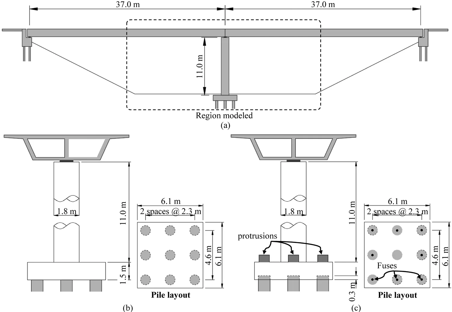
Fig.7 (a) Prototype configuration and dimensions of (b) the PH pier and (c) the CRPF pier
The CRPF pier was designed to provide an elastic lateral force capacity of no less than 1890 kN (425 kips)and be capable of reaching a 5% column drift ratio,which is comparable to those of the PH pier.Given that the CRPF pier was supported on the pile foundation with geometry similar to that of the PH pier (Fig.7(c)),following the previously mentioned design procedure,the decompression force was computed to be equal to 1170 kN (263 kips).All piles, except the one directly underneath the column, were connected to the pile cap with a single bar fuse.The resulting fuse area was calculated to be 1516 mm2(2.35 in2).Given that the ultimate strain capacity of the fuse bar steel was 0.11 mm/mm (in/in), the required length of the bar fuse was computed to be 2.1 m (6.9 ft) to accomplish the design drift ratio.The pile cap was made with 0.9 m (3 ft)-tall protrusions to accommodate the fuses.Given that the pile cap lifts 0.23 m (0.75 ft) from the piles for a 5% drift ratio, the piles protruded 0.3 m (1 ft) into the pile cap,which also provided a sufficient bearing area to transfer lateral forces from the pile cap to the piles.The column in the CRPF pier was reinforced with seventy-two #43M(#14) longitudinal reinforcing bars and a #19M (#6)reinforcing spiral with a spacing of 102 mm (4 in) to ensure its elasticity.
4.2 Numerical model
The analyses were conducted using the computer software SAP2000®.Figure 8 illustrates the 3D numerical models for the PH and CRPF piers.In the models, the superstructure was represented by a concentrated mass,which was connected to the pier column using a rigid link.For the PH pier, the column was modeled as an elastic beam-column element with an effective moment of inertia that was approximated based on Caltrans (2019).The nonlinear behavior of the column was captured using a concentrated fiber hinge assigned to the base of the column.For defining the hinge, the concrete and reinforcing steel were modeled following Manderet al.(1984) and Caltrans (2019), respectively.The momentrotation response of the hinge was characterized by integrating the stress-strain relation of the uniaxial fibers on the column section over a 1397 mm (55 in) equivalent analytical plastic hinge, which was determined as per Caltrans (2019).The pile cap was modeled using elastic thick shell elements, with a thickness of 1.5 m (5 ft), and its thickness was reproduced by the use of rigid links assigned to the top and bottom of the shell elements.The piles were represented by elastic beam-column elements, and the lateral and vertical soil resistances to the piles were simulated through the use of a set of nonlinear springs prescribed byp-yandt-zcurves,respectively.Given the soil properties and conditions,thep-yandt-zcurves were established according to empirical formulations proposed for stiff clay without free water (Welch and Reese, 1972; API, 2002).In order to capture the formation of gaps between the piles and cohesive soil when the piles are subjected to cyclic load,compression-onlyp-ysprings with the Takeda hysteresis model were assigned on four sides of the pile elements.Thet-zsprings were defined to provide both compressive and tensile resistance.The column, pile cap, and piles of the PH pier were modeled as fixed to one another.
For the CRPF pier, the column was modeled using an elastic beam-column element and fixed to the pile cap shell elements.The thickness of the pile cap and its protrusions were reproduced by the use of rigid links, similar to the PH pier model.The piles of the CRPF pier and the surrounding soil were modeled to be identical to that of the PH pier model.The friction between the protruding part of the piles and shallow sockets produced some resistance to the uplift of the pilecap.However, this resistance was negligible compared to the gravity effects.When the pile cap uplifted from the decompressed piles, the shallow sockets, combined with the friction between the pile cap and the top of piles, transferred lateral forces from the pile cap to the piles.Compared to the sockets that transferred lateral force through the bearing on side faces, the friction contributed much less lateral force resistance.Therefore,the zero-length, compression-only gap elements (Fig.8)were assigned between the pile elements and the rigid links representing the pile cap thickness, which allowed pile cap lift from the piles and transferred shear forces,but neglected the effects of friction.For verification purposes, the rocking pile foundation tested by Guanet al.(2018) was modeled utilizing gap elements.Good agreement between the measured and computed uplift displacement of the pile cap (Fig.9) indicated that this configuration was capable of simulating the rocking mechanism of the pile cap.The bar fuses in the CRPF pier were modeled using uniaxial nonlinear links.These links were assigned by connecting the pile cap rigid links to the pile beam-column elements, and their forceelongation response was defined according to the White model (White, 2014), as shown in Fig.2(b).In light of the findings by Kalliontzis and Sritharan (2018), the mass and stiffness proportionate to Rayleigh damping were used for both models, with 5% and 7% damping ratios in the first and third modes, which were the most predominant translational components in the lateral and vertical directions.The first four natural periods of the CRPF piers were 1.207 s, 1.207 s, 0.079 s, and 0.052 s,and those of the PH pier were 1.202 s, 1.202 s, 0.078 s,and 0.040 s.The first two periods were identical because both piers were symmetrical in translational directions.Two piers exhibited similar dynamic characteristics, as they had comparable initial stiffness.
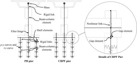
Fig.8 Schematic of the numerical models
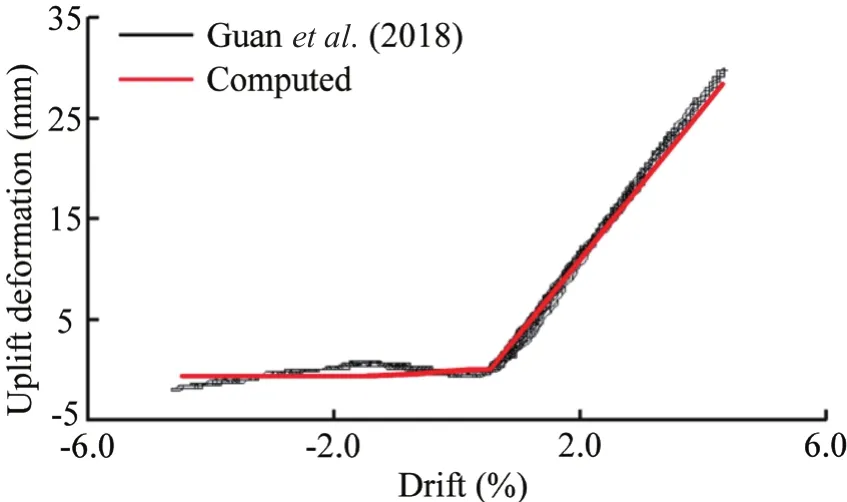
Fig.9 Comparison between measured and computed pile cap uplift displacement
4.3 Response to static cyclic loads
Figure 10(a) shows the force-displacement responses of the CRPF and PH piers that were subjected to static cyclic loads.The column top displacement was increased in steps so that column drift ratios of 2%, 4%,6%, 8%, and 10% was achieved.For the CRPF pier, the pile cap uplifts with respect to the two exterior piles(i.e., the left and right piles) and the pile underneath the column (i.e., the middle pile) were plotted as a function of column displacement, as shown in Fig.10(b).Figure 10(c)presents the force in the bar fuses that connect the two exterior piles.Under the cyclic loads, as expected,the CRPF pier rocked symmetrically on the top of the piles.Pile decompression took place at a lateral load of 1086 kN (244 kips).With the pile cap lifted from the piles, the bar fuses were subjected to tension, thereby producing additional resistance to the lateral force.After the fuse yielded at a lateral load of 2010 kN (452 kips),inelastic behavior dominated the response of the CRPF pier, with a slightly positive slope.When the lateral force was reversed, the pile cap set back on the piles,and the elongated bar fuses yielded in compression.The bar fuse eventually fractured at a displacement of 1.07 m (42.1 in), corresponding to a column drift ratio of 8.6%.The superstructure weight provided the necessary restoring force to re-center the pier when the lateral force was removed.Except for the bar fuses, none of the components in the CRPF pier experienced inelastic level forces.Thus, even after a large displacement, the pier remained functional for regular use.The CRPF pier can restore its seismic resistance by replacing the bar fuses.In contrast, the PH pier formed a plastic hinge in the column.As indicated in Fig.10(a), its damage levels,corresponding to the different displacements, were estimated as per Hose and Seible (1999).This revealed that, although the PH pier ensured life safety when subjected to large displacements, it sustained significant damage and residual displacement, which required being closed for weeks or even months for repair, or even longer for replacement (Marsh and Stringer, 2013).Figure 10(d)compares the equivalent viscous damping of the CRPF and PH piers.As expected, the PH pier dissipated more energy for a given displacement.Starting from a displacement of 0.25 m (9.8 in) (i.e., a column drift ratio of 2%), the equivalent damping of the CRPF pier was more than 10% and reached approximately 20% before the bar fuse fractured.It is worth noting that the damping ratio of the CRPF pier can be increased or decreased by adjusting the pile group layout and dimensions of the bar fuses.
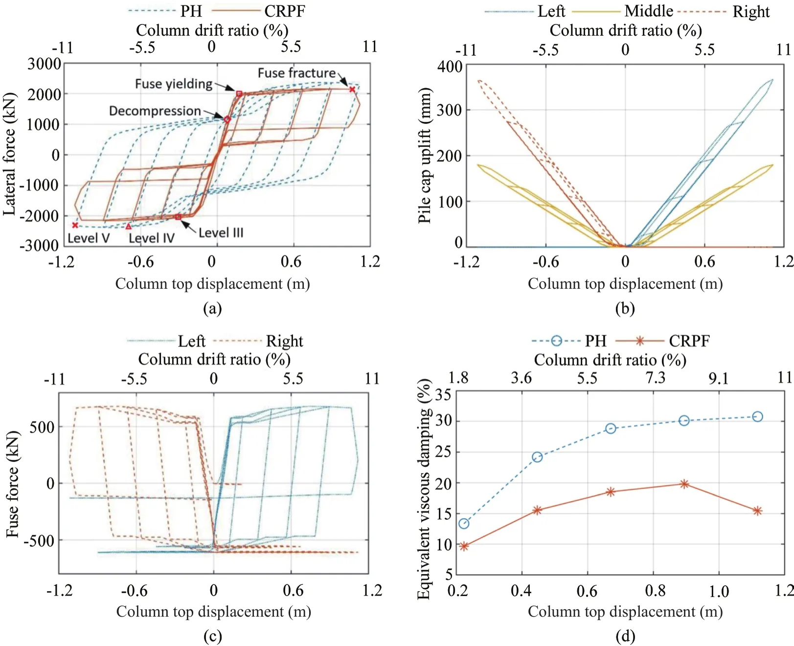
Fig.10 Responses to static cyclic loads: (a) force-displacement behavior; (b) pile cap uplift in the CRPF pier; (c) change in fuse force; and (d) equivalent viscous damping ratio
Figures 11(a) and 11(b) depict force-displacement responses at the head of the exterior piles in the lateral and axial directions.When subjected to cyclic loads,the displacements of the piles in both the CRPF and PH piers were small, thus confirming that the design of the pile group was satisfactory.Compared with the momentresisting connections between the piles and the pile cap in the PH pile, the pinned connections used in the CRPF pier reduced the lateral stiffness of the piles.When one side of the CRPF pier lifted from the piles, only the piles underneath the opposite side transferred the lateral loads.Thus, the individual pile in the CRPF pier experienced higher lateral forces than those of the PH pier.The barfuses in the CRPF pier transferred tensile forces to the piles, while their yield strength limited the tensile force acting on the piles, to less than 679 kN (153 kips),regardless of the magnitude of the applied lateral force.
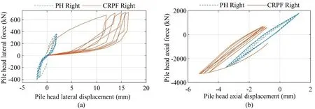
Fig.11 Force-displacement response of the exterior piles in (a) the lateral direction and (b) the axial direction
4.4 Response to dynamic free vibrations
A free vibration study was carried out to examine the dynamic characteristics of CRPF and PH.Two rectangular pulse accelerations were applied laterally as base excitations.As shown in Fig.12(a), the duration of the excitation was 0.5 s, and the amplitude of the lowintensity excitation and high-intensity excitation were 0.1 g and 0.5 g, respectively.Figure 12(b) shows the column lateral displacement time histories for the CRPF and PH piers when subjected to the two excitations, and Fig.12(c) depicts the force-displacement responses of the two piers.For demonstrating the rocking response of the CRPF pier, the pile cap uplift with respect to the exterior piles was plotted in Fig.12(d) as a function of time.When subjected to the low-intensity excitation, the pile cap of the CRPF pier did not lift from the piles, and the column top displacement primarily resulted from elastic deformation of the column.The PH pier alsobehaved elastically.Because of the similarity between their elastic characteristics, the CRPF and PH piers exhibited comparable responses.
As the amplitude of the excitation increased to 0.5 g, both the CRPF and PH piers underwent a maximum displacement of approximately 0.44 m (17 in),corresponding to a column drift ratio of 3.9%.The large displacement caused a plastic deformation in the column of the PH pier, leading to a considerable residual displacement of 0.18 m (7 in), corresponding to a column drift ratio of 1.6%.In contrast, the CRPF pier re-centered following the excitation.Its force-displacement response displayed a characteristic flag-shape hysteretic loop,indicating that a significant amount of energy dissipated during the large displacement cycle, but minimal energy dissipation took place for small displacement cycles.Consequently, the rocking response of the CRPF pier was abruptly decayed during the first displacement cycle, but afterward, the pier continuously rocked at the small displacement amplitude for several cycles.The rocking mechanism excited the vertical inertia effects and induced an impact between the pile cap and piles,causing a change in column axial force.As shown in Fig.12(e), when subjected to the high-intensity excitation, the changes in the column axial force were more pronounced for the CRPF pier than for those of the PH pier, and the impulses can be detected when the impacts occurred.
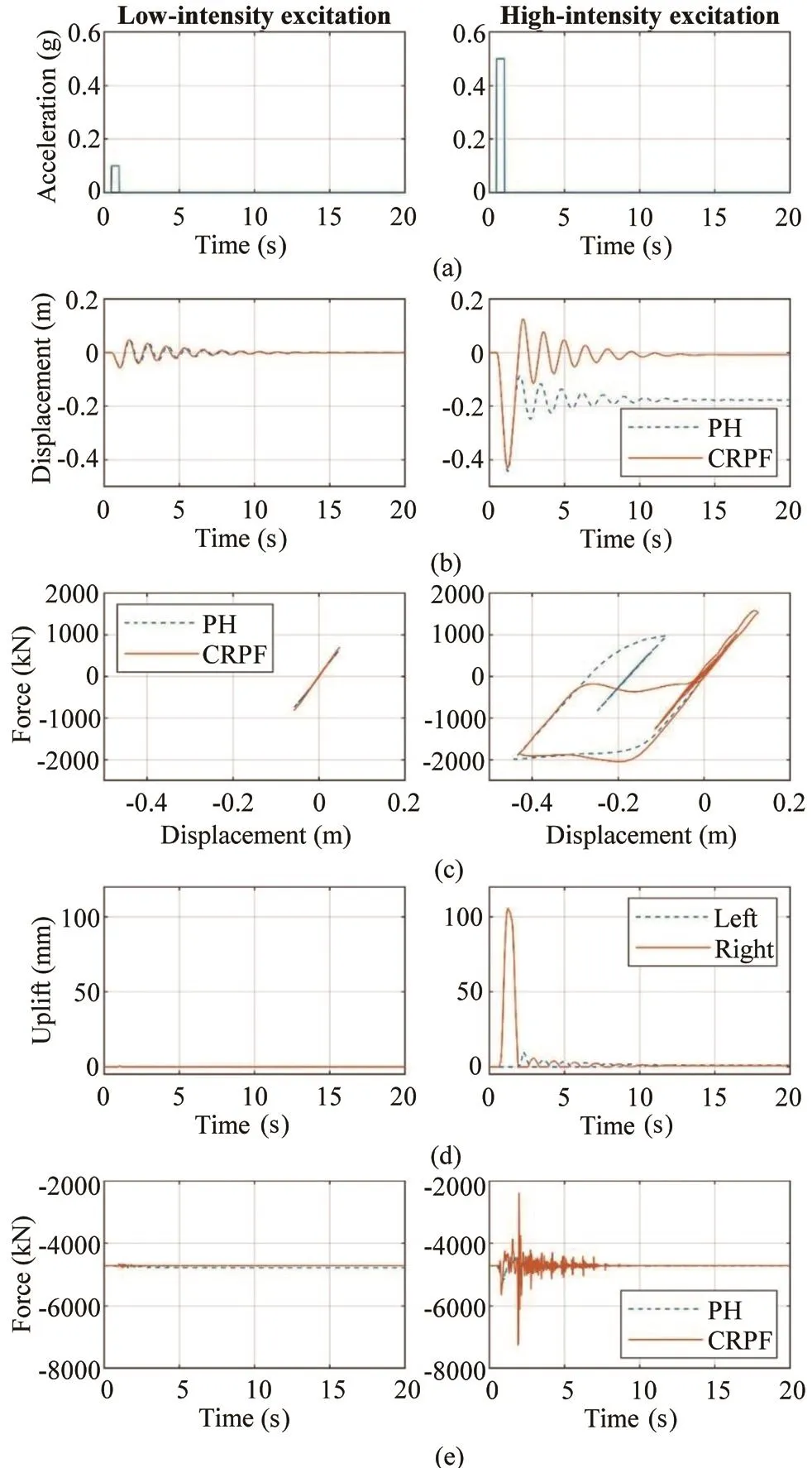
Fig.12 Free vibration responses: (a) base excitation; (b) column displacement history; (c) force-displacement response;(d) pile cap uplift for the CRPF pier; and (e) axial force in the column
4.5 Response to earthquake ground motions
To further analyze the behavior of the CRPF pier,the numerical models were subjected to a total of nine unidirectional earthquake ground motions, with the details presented in Table 1.All ground motion records were sourced from the PEER strong motion database(PEER, 2019).The selected ground motions consisted of six non-pulse-like sets and three pulse-like sets,representing both free-field and near-fault ground motions.These ground motions were scaled such that their spectra for 5% damping ratio at 1.2 s, which is the fundamental period of the CRPF and PH piers, matched 100%, 125%, and 150% of the Caltrans design spectrum for a magnitude 8.0 earthquake at a Type C soil site with a peak ground acceleration (PGA) of 0.8 g (Caltrans,2019).Table 1 also lists the scaling factors used for matching 100% of the design spectrum.
Table 2 summarizes the response parameters of the CRPF and PH piers for each of the ground motions.The maximum column drifts of the CRPF were comparable or slightly higher than for those of the PH pier.This behavior was attributed to lower hysteretic damping for the CRPF pier.The residual drift of the CRPF pier remained below 0.1%, benefiting from its re-centering capacity.However, the residual drifts of the PH pier were up to 0.732%.For the CRPF pier, the strains of the bar fuses were less than 0.084 (except for 150% EQ 4), corresponding to 49% of the ultimate strain capacity of the bar steel.As the rocking mechanism causes the change in the column axial force, for comparison,Table 2 lists the maximum compressive axial force in the column of the CRPF and PH piers.The maximum force in the CRPF pier was 13352 kN (3001 kips),corresponding to an axial load ratio of 18%.
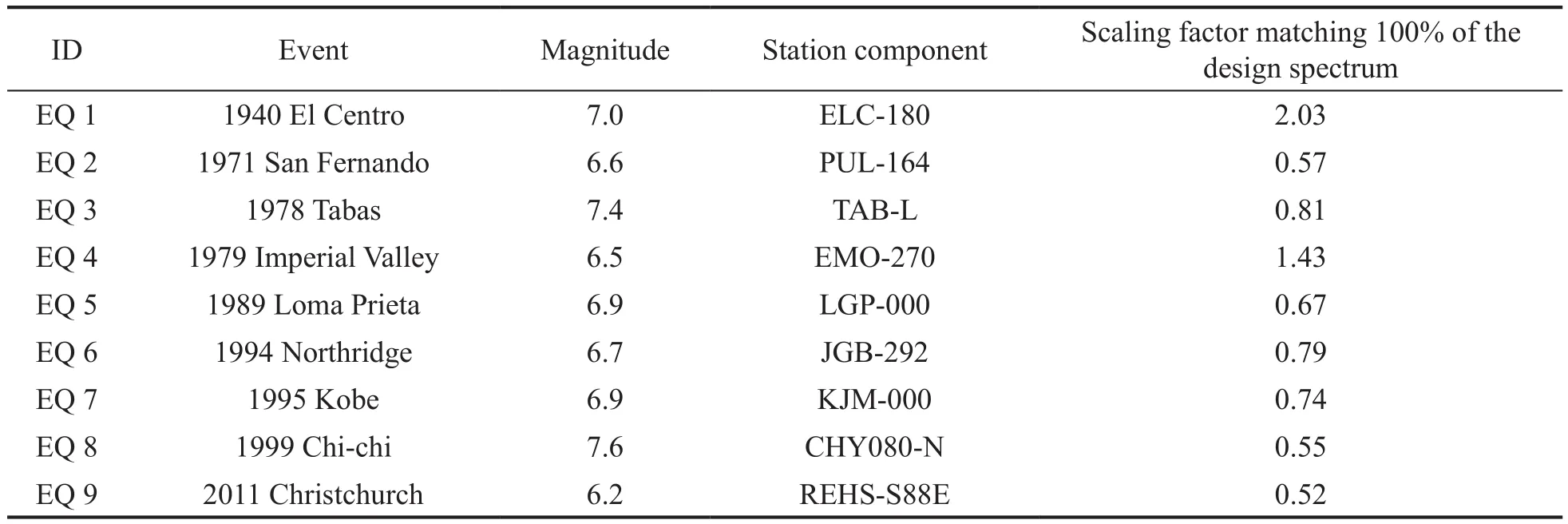
Table 1 Summary of selected earthquake ground motions
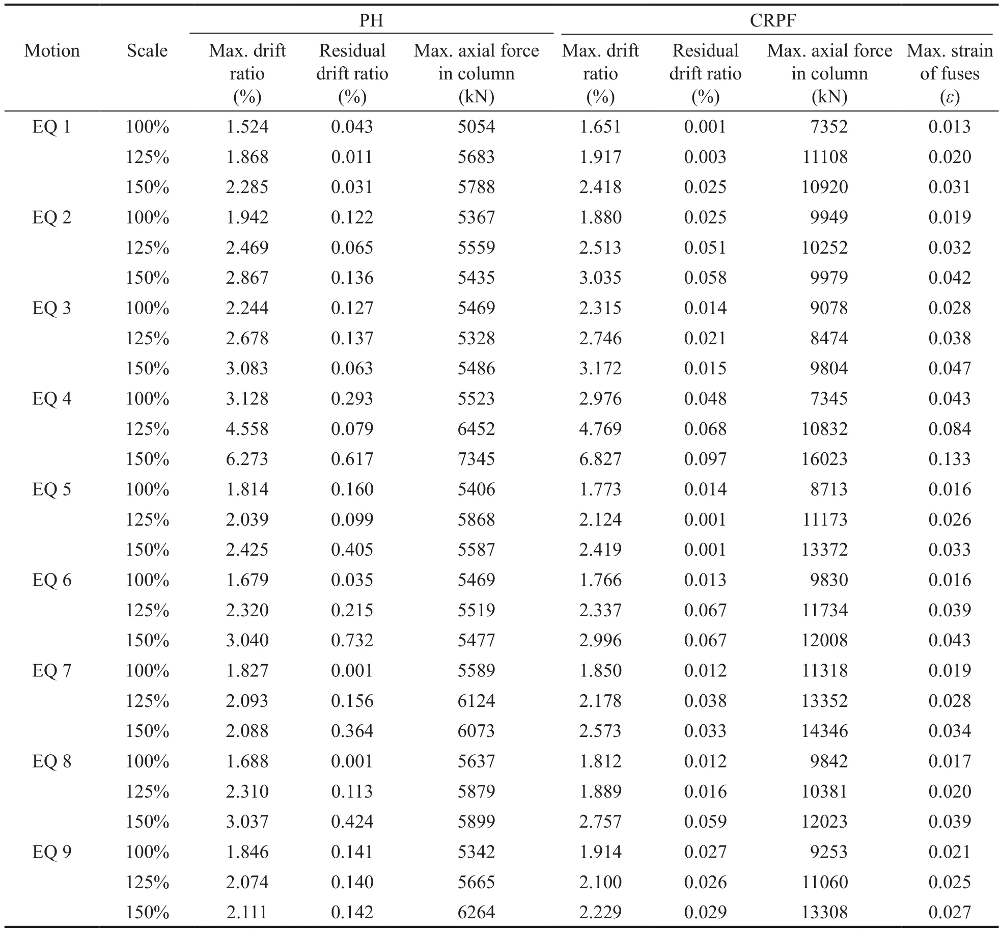
Table 2 Response parameters for the CRPF and PH piers, subjected to ground motions
Figure 13 compares the force-displacement hysteresis behaviors of the CRPF and PH piers for ground motions scaled to a 150% design spectrum.All the hysteresis curves exhibited no major strength degradation, indicating that both piers ensured life safety and collapse prevention.For the PH pier, given that the lateral displacement corresponding to damage level III was approximately 0.3 m (11.8 in), it could experience moderate-to-significant damage and require closure for repairing when subjected to ground motions of 150%EQ 2, EQ 3, EQ 4, EQ 6, and EQ 8.By contrast, despite the inelastic yielding of the bar fuses as designed, the CRPF pier does not experience inelastic deformation in the column, pile cap, and pile foundation, and thus can be immediately accessible for regular traffic after experiencing ground motions.
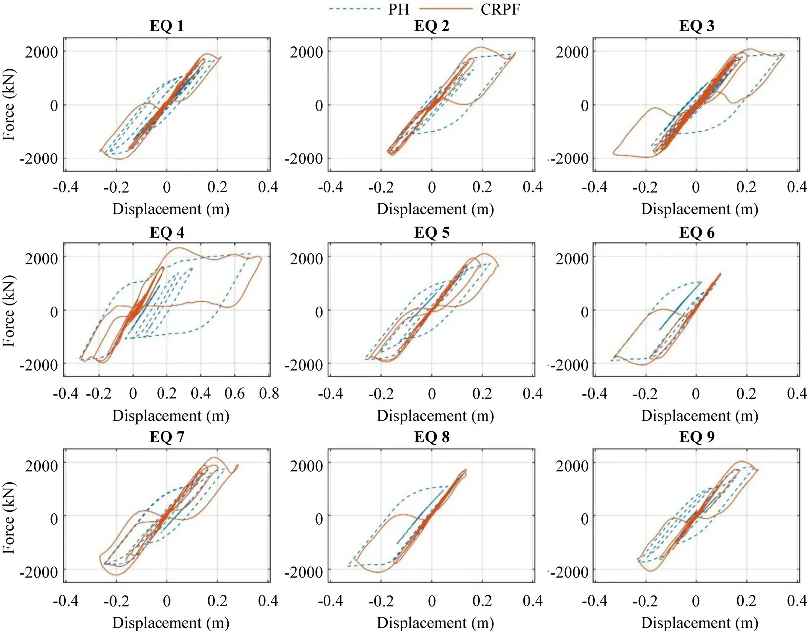
Fig.13 Force-displacement behaviors of the CRPF and PH piers
5 Conclusions
This paper presents the controlled rocking pile foundation (CRPF) system with replaceable bar fuses,which is designed for seismic resilience.The CRPF system features a precast pile cap that is allowed to uplift from piles and replaceable bar fuses that connect the pile cap and piles.When subjected to strong earthquake excitation, the uplift of the pile cap causes the fuses to undergo inelastic deformation and dissipate seismic energy.The superstructure weight acting on the CRPF system provides a restoring force to re-center the system.The CRPF system can be constructed on different types of pile foundations, and the connections are conceptualized to efficiently attach the bar fuses to the system.The seismic response of a bridge pier utilizing the CRPF system (CRPF pier) was numerically investigated and compared to that of a bridge pier designed to develop a flexural plastic hinge in the column (PH pier).The three-dimensional nonlinear analytical models of the CRPF and PH piers were subjected to static cyclic loads, dynamic free vibrations, and earthquake ground motions.The following conclusions were reached, based on the findings of this analytical study:
· The CRPF system design, following a simplified approach, successfully achieved the design objectives.When subjected to cyclic lateral loads acting at the top of the column, the resistance of the CRPF pier was comparable to that of the PH pier, as designed.The CRPF pier reached a column drift ratio of 8.6%,without significant strength degradation, and exhibited sufficient re-centering capacity.The CRPF pier also resulted in an elastic response of the column, pile cap,and pile foundation.The inelastic behavior was limited to the bar fuses, as expected.The inelastic deformation of the bar fuses provided an equivalent viscous damping ratio of more than 10% and reached approximately 20%before the bar fuses fractured.It is worth noting that the damping ratio corresponding to the configuration of the pile foundation and bar fuses can be adjusted to meet the design requirements.
· When subjected to low-intensity excitation with a duration of 5 s.and an amplitude of 0.1 g, the CRPF and PH piers deformed in an elastic manner and exhibited comparable free vibration behavior because of their similar elastic characteristics.As the amplitude of the excitation increased to 0.5 g, the pile cap of the CRPF pier lifted with respect to the pile foundation,causing the bar fuses to undergo inelastic deformation and provide a large amount of hysteretic damping, thus abruptly decaying the free vibration of the CRPF.The energy dissipation of the CRPF pier was significantly reduced after the first cycle of the free vibration because the fuses remained elastic during the ensuing cycles.
· Both the CRPF and PH piers provided life safety and collapse prevention when subjected to earthquake ground motions.The column drift ratio of the CRPF pier did not exceed 6.83%, and the residual drift ratio wasless than 0.1% when subjected to ground motions scaled to 150% of a Caltrans design earthquake.In addition, all components except the bar fuses remained elastic, and the strain of the bar fuses remained below acceptable limits, confirming the seismic resilience of the CRPF system.Note that as the pile cap of the CRPF pier rocked on the top of the pile foundation, the column axial load ratio increased up to three times the design value,suggesting the necessity of retaining a low column axial load ratio for design.
· In this study the seismic resilience of the CRPF system is confirmed by using a numerical approach.A suggestion for future work is to experimentally test the CRPF system under seismic ground motions, thus better understanding the effects due to local behaviors(e.g., damage potentially occurring at the pile heads,plus energy dissipation due to impact) and further investigating its seismic responses.
Acknowledgement
This work was jointly supported by the National Natural Science Foundation of China (Grant Nos.52008092, U1934205, 51908123), the China Postdoctoral Science Foundation (Grant No.2021M690034), the International Postdoctoral Exchange Program of China and the Zhishan Postdoctoral Fellowship Program.These supports are kindly appreciated and gratefully acknowledged.
杂志排行
Earthquake Engineering and Engineering Vibration的其它文章
- Property estimation of free-field sand in 1-g shaking table tests
- Dynamic p-y curves for vertical and batter pile groups in liquefied sand
- Underground blast effects on structural pounding
- An analytical model for evaluating the dynamic response of a tunnel embedded in layered foundation soil with different saturations
- Seismic ground amplification induced by box-shaped tunnels
- Shaking table test of subgrade slope reinforced by gravity retaining wall with geogrids
