An analytical model for evaluating the dynamic response of a tunnel embedded in layered foundation soil with different saturations
2022-07-12DiHongguiGuoHuijiZhouShunhuaWangBinglongHeChaoandZhangXiaohui
Di Honggui , Guo Huiji , Zhou Shunhua , Wang Binglong , He Chao and Zhang Xiaohui
1.Key Laboratory of Road and Traffic Engineering of the Ministry of Education, Tongji University, Shanghai 201804, China
2.The Technical Center of Shanghai Shentong Metro Group Co., Ltd., Shanghai 201103, China
3.Shanghai Key Laboratory of Rail Infrastructure Durability and System Safety, Tongji University, Shanghai 201804, China
Abstract: This paper proposes an analytical model for evaluating the dynamic response of an underground railway tunnel in layered foundation soil with different saturations.The soil is modeled as layered media, and the circular tunnel lining is modeled as an infinite Flügge cylindrical shell.The separation of variables method is used to solve the motion equation of the shell, and the wave equation of the soil is solved using the Helmholtz decomposition theorem.A dynamic matrix reflecting the wave vectors of soil layers is established using the transfer matrix method.Based on boundary conditions, the tunnel-soil model is coupled using the transformation method of plane wave functions and cylindrical wave functions.The proposed model is validated by comparison with existing tunnel models, and the effects of saturation and the layered properties of soil on the dynamic response of a layered tunnel-soil system is demonstrated via case studies.
Keywords: tunnel; unsaturated soil; saturation; transfer matrix method; wave function transformation
1 Introduction
Underground railways play an important role in alleviating ground traffic congestion in densely populated cities.However, with an increase in the number of underground railway lines, issues related to train-induced environmental vibration and long-term tunnel settlement in soft soils have become a matter of great concern (Laiet al., 2005; Lopeset al., 2016; Diet al., 2020b).Train-induced vibration affects the everyday lives of nearby residents, the functioning of precision instruments, and the preservation of ancient buildings.It also causes tunnel structure damage and leads to increasing tunnel maintenance costs (Zhouet al., 2018;Diet al., 2021).Therefore, regarding environmental protection and the serviceability of railway tunnels, a reasonable understanding of the dynamics of the tunnelsoil system is required.
Several tunnel models have been established to study train-induced vibrations from underground railways.Metrikineet al.(2000) proposed the Euler beam model,in which a tunnel is simplified as a beam embedded in single-phase elastic soil medium.The foundation of this model was developed into a layered half-space soil foundation (Haak, 2000; Koziolet al., 2008).Based on the discrete wavenumber method, Forrest and Hunt (2006) established the pipe-in-pipe (PiP) model,simplifying the tunnel as an infinite cylindrical shell embedded in a hollow circular cylinder soil foundation.Subsequently, Husseinet al.(2007, 2014), Kuoet al.(2011), Clotet al.(2016), Zenget al.(2014), Diet al.(2016, 2020b), and Heet al.(2018) further developed the PiP model to consider track structure, the doubledeck tunnel, the double-line tunnel, soil saturation, and the layered characteristics of soil.Heet al.(2019a,2019b) and Zhouet al.(2020) used the wave function method, considering the characteristics of the saturated layered half-space soil foundation, two parallel tunnels,tunnel segments, vehicle dynamics, and rail roughness.
Using models based on numerical methods,Thiede and Natke (1991) and Gardien and Stuit (2003)established the two-dimensional (2D) method and three-dimensional (3D) finite element (FE) method,respectively.To improve the calculation efficiency of the FE methods, Xie and Sun (2003) and Bianet al.(2012)established the 2.5-dimensional (2.5D) FE method based on the invariance of tunnel axial direction size.Shenget al.(2005) established the 2.5D finite element-boundary element (FE-BE) model using Fourier transform andthe discrete wavenumber method, which uses the Green function to express an infinite field and avoid the error of manually setting the boundary.Heet al.(2017, 2018) further developed the 2.5D FE-BE model,considering the characteristics of the saturated layered foundation and quasi-rectangular tunnels.In addition,Yang and Hung (2001, 2010) proposed a 2.5D finite element-infinite element model, Degrandeet al.(2006)proposed a periodic FE-BE model for subway tunnel vibration using Floquet transform, Nejatiet al.(2012)proposed a finite difference model, and Zhu and Liang(2020) proposed a finite difference model based on finite element-indirect boundary elements (FE-IBEs).
In addition to the analytical and numerical models,Huanget al.(2015), Yanget al.(2020), and Darliet al.(2021) studied the dynamic response characteristics of a foundation-tunnel system, using a model test.Based on measured data of subway vibrations, Kuppelwiese and Ziegler (1996), Madshuset al.(1996), and Hoodet al.(1996) proposed empirical models.However,these models have the disadvantage of being only regionally applicable because they were proposed based on measured data from specific regional geological environments.To improve prediction accuracy by combining the advantages of the two types of models,Kouroussiset al.(2017) proposed the empirical-numerical coupled model for vibration prediction.
However, the existing tunnel models simplified the foundation as a single-phase medium or two-phase saturated porous medium, rarely considering soil as a three-phase unsaturated medium foundation.Gaoet al.(2019) analyzed the dynamic response of ground surface railways on unsaturated foundations.Diet al.(2020a)and Guoet al.(2020) proposed analytical models to analyze the dynamic response of tunnels in unsaturated full-spaces or half-spaces, respectively.However, in practice, the soil foundation is layered, simultaneously coexisting as a single-phase medium, saturated porous medium, and unsaturated porous medium.Hence,the aforementioned models do not sufficiently take into account these soil properties in their approach to modeling.
In this study, an analytical model is proposed for evaluating the dynamic response of a tunnel embedded in layered foundation soil with different saturations.The circular tunnel lining is modeled as an infinite Flügge cylindrical shell (Forrest and Hunt, 2006), and the foundation soil is modeled as horizontally layered media.Based on the boundary conditions, the model is coupled in the frequency domain and wave number domain using the transfer matrix method and wave function transformation method.The effect of soil saturation on the dynamic response of the tunnel-layered soil system is analyzed.The advantage of this analytical model lies in its high computational efficiency and better simulation of realistic soil layers, in which single-phase, two-phase saturated, and three-phase unsaturated soils coexist.
2 Tunnel-layered soil model
2.1 Assumptions
The tunnel lining is modeled as an infinite Flügge thin-walled cylindrical shell composed of homogeneous,isotropic, and linear elastic materials.The soil is modeled as layered half-space or bedrock covered withNhorizontal layers with different saturations, as shown in Fig.1.
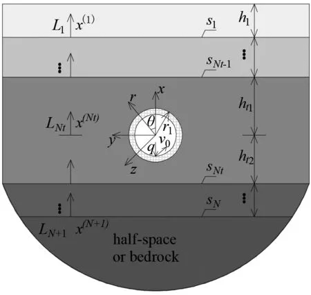
Fig.1 Layered half-space model and coordinate system
L1,L2, …,LN+1represent the soil layer number,andLNtrepresents the number of the soil layer (n=Nt)where the tunnel is situated;h1,h2, …,hnrepresent the thickness of soil layers;ht1andht2represent the distances from the tunnel center to the upper and lower interface of soil layerLNt;snrepresents the interface between soil layersLn-1andLn.
For model simplification, each soil layer is assigned its own coordinate system.x(1),x(2), …,x(N+1)represent coordinate values in the independent coordinate system of different soil layers.The detailed coordinate system is defined as follows: (i) the soil layer (n<Nt) above the layer in which the tunnel is situated adopts a Cartesian coordinate system, and the coordinate origin is the bottom of the soil layer; (ii) the soil layer (n>Nt) below the tunnel layer adopts a Cartesian coordinate system,and the coordinate origin is the top of the soil layer; (iii)both cylindrical coordinates and Cartesian coordinates are used in the soil layerLNt, and their origin is the center of the tunnel.
To establish and solve the tunnel-soil model, the following assumptions are made for the boundaries:
(1) At the ground surface, stress dissipates to zero and the surface is pervious to water and air.
(2) The bottom boundary can be divided into two cases: i) the bottom boundary of the model is a halfspace, and the displacement, stress, and pore pressure are equal to zero at an infinite distance; ii) the bottomboundary of the model is bedrock, the displacement at the interface between bedrock and the soil layer is zero,and the interface is impervious to water and air.
(3) The displacement, stress, pore pressure, and seepage at the interfaces of different soil layers are continuous.
(4) Displacement and stress at the interface of the tunnel and soil are continuous, and the tunnel lining is impervious to water and air.
2.2 Total wave field of foundation soil
Before deriving the solution to the tunnel-layered soil model in the frequency and wavenumber domains,the Fourier transform of timetto frequencyωand the Fourier transform of directionzto wave numberkzare defined.In the Cartesian coordinate system, the Fourier transform of directionyand wave numberkyalso is defined.
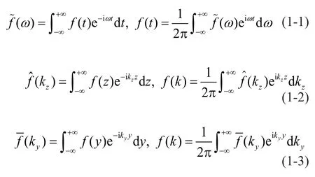
where, the superscript ~ refers to the quantity in the frequency domain; the superscript ^ refers to the quantity in thez-direction wavenumber domain; the superscript — represents the quantity in they-direction wavenumber domain.
To achieve a unified total wave field expression of the different media, i.e., single-phase elastic medium,two-phase saturated porous medium, and three-phase unsaturated porous medium, the total wave field expression of unsaturated soil is solved first, after which the total wave field of single-phase elastic soil or saturated soil can be obtained by parameter degradation.
The practical wave equation for unsaturated soil can be written in the form ofub-v-w(Guoet al., 2020):
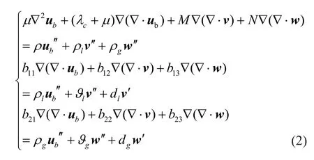
where the subscriptss,b,l, andgrepresent the variables of soil grain, soil framework, pore water, and air,respectively; the superscripts ′ and ′ represent the first and second derivative, respectively;ubrepresents the displacement vector of the soil framework;vrepresents the relative displacement vector of pore water and the solid framework, andwrepresents the relative displacement vector of air and the solid framework;andλandμrepresent the Lamé constants of the soil framework.The other variables are shown in Appendix A.
The seepage continuity equation and constitutive equations in unsaturated soil are as follows:
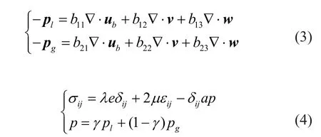
whereprepresents the pressure of the pore fluid;σijrepresents the stress on the solid framework;erepresents the volumetric strain;δijrepresents the Kronecker symbol; andεijrepresents the displacement components;andγrepresents the effective stress coefficient.
Based on the principle of Helmholtz vector decomposition, the displacement components in Eq.(2)can be expressed as:

where the subscripts SH, SV, and P represent theSH(shear) wave, SV (shear) wave, and P (compression)wave, respectively; andψ,φ, andχrepresent the potential functions of the soil framework, pore water,and air, respectively.
Considering the steady-state response, by substituting Eq.(5) into Eq.(2) and performing the Fourier transform in Eq.(1-1), the following equations for the frequency domain are obtained:
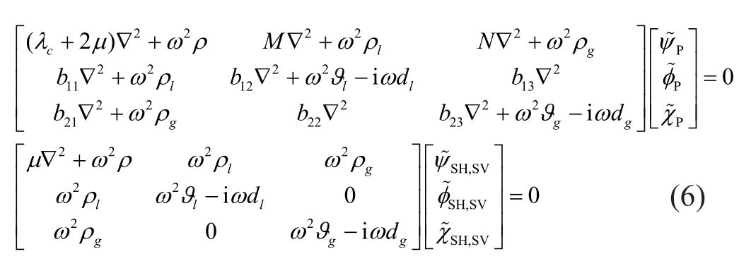
where, the subscript “,” means that there are two identical systems of equations.
To ensure that the differential Eq.(6) has non-zero solutions, the coefficient determinants of Eq.(6) must be equal to zero.Then, the Helmholtz equations can beobtained:

wherekp1,kp2, andkp3represent the three types of longitudinal wave numbers in unsaturated soil, andksrepresents the transverse wave numbers in unsaturated soil.
After substituting Eq.(7) into Eq.(6), the potential functions can be expressed as:
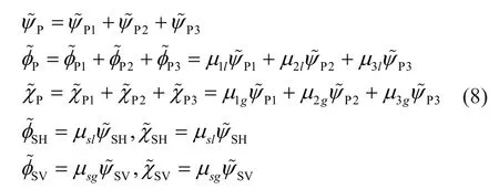
where the expressions of theμvariables are summarized,as listed in Appendix B.
After the total wave number of the foundation soil is solved by Eq.(7), the expression of potential function could be defined both in the Cartesian coordinate system and in the cylindrical coordinate system (Paoet al.,1973).
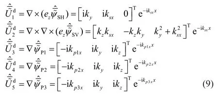
As for the displacement functions of unsaturated soil related to the Cartesian coordinate system, the Fourier transform in thezdirection and theydirection are carried out to obtain the expression of the displacement component in the frequency domain and double wave number domain (z-direction andy-direction wave number domain),, can be expressed as:
As for the displacement functions related to the cylindrical coordinate system, Fourier transform in thezdirection and Fourier series decomposition in directionθ(modal decomposition) are carried out to obtain the expression of the displacement component in the frequency domain and wave number domain of each modal.can be expressed as:
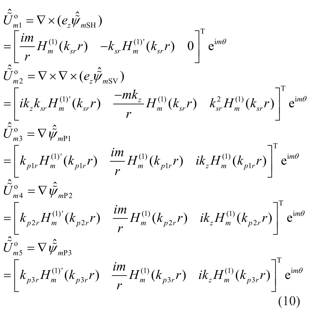
wheremis the number of circumferential modes;represent the displacement potential functions for the cylindrical waves diverging from the center of a circle (named ‘outgoing waves’) of the SH, SV, P1, P2, and P3waves related to the cylindrical coordinate system, respectively;Hm(1)represents the Hankel function of the first kind; andandrepresent wavenumbers in therdirection of the S and P waves with non-negative imaginary parts (Imksr> 0, Imkp1r,p2r,p3r> 0).represent the displacement potential functions for the cylindrical waves converging from all sides to the center of a circle (named regular waves), which can be obtained by replacingHm(1)with the Bessel function of the first kindJm(1)in Eq.(10).
By substituting Eqs.(9)-(10) into Eqs.(3)-(4), the stress vector, excess pore water pressure vectorair pressure vectorin the Cartesian coordinate system, and the stress vector, excess pore waterpressure vectorand air pressure vectorin the cylindrical coordinate system can be obtained as:
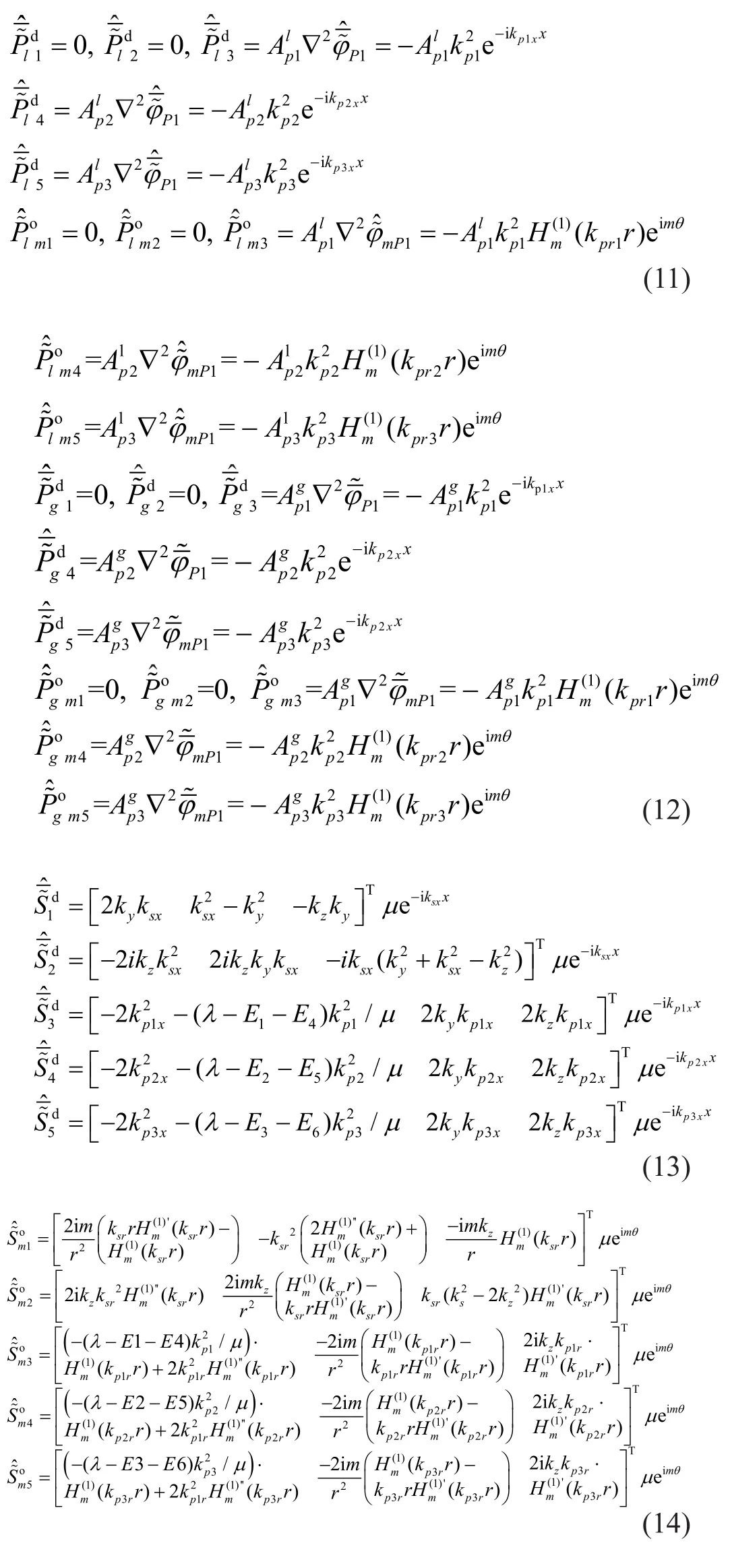
where the expressions ofAandEare summarized, as listed in Appendix C.
The many scattering surfaces in the model cause different types of waves.For the soil layer above or below the tunnel (n<Ntorn>Nt), each layer has two horizontal soil interfaces, and hence, there are two kinds of waves, i.e., up-going and down-going.The total wave field expression can be given as Eq.(15-1).The soil layer of the tunnel (n=Nt) has two horizontal soil interfaces and a cylindrical interface; hence, there are three kinds of wave, i.e., up-going, down-going, and outgoing.The total wave field expression can be given as Eq.(15-2).
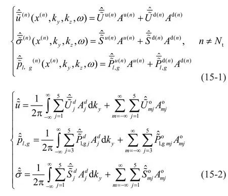
Using parameter degradation of the three-phase medium, the total wave field expressions for the twophase and single-phase medium also can be obtained(Guoet al., 2020).In this calculation, if the unsaturated soil parameterSrapproachesSw0,and the porosityn0approaches 0, then Eq.(15) degenerates to the total wave field expression of a single-phase elastic medium soil.If the unsaturated soil parametersSrandSeapproach 1 andAsapproaches 0, then Eq.(15) degenerates to the total wave field expression of two-phase saturated soil.
2.3 Cylindrical shell equations
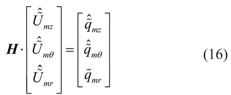
The vibration characteristics of the tunnel lining are simulated using a vibration equation for Flügge cylindrical shells.When the radial direction load is applied at the invert of the tunnel (as shown in Fig.1),the matrix expression of the shell equilibrium equation in the frequency-wavenumber domain can be obtained(Forrest and Hunt, 2006):
2.4 Solution for particular boundary conditions
To solve the coupling of different kinds of waves in the same boundary condition, transformation relationships between plane waves (up-going and downgoing) and cylindrical waves (outgoing and regular) are introduced (Boströmet al., 1991):
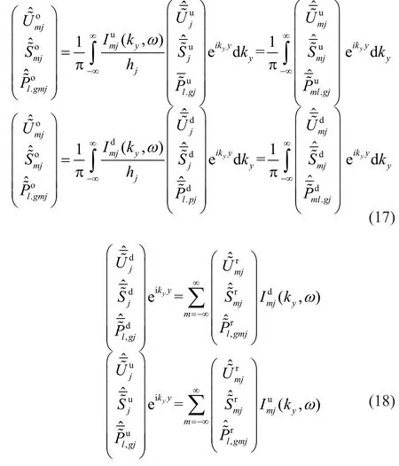
Based on Eqs.(17)-(18), the model is solved by coupling the boundary and interface conditions.
2.4.1 Ground surface
According to the boundary and interface assumption(1), the following equations can be obtained:
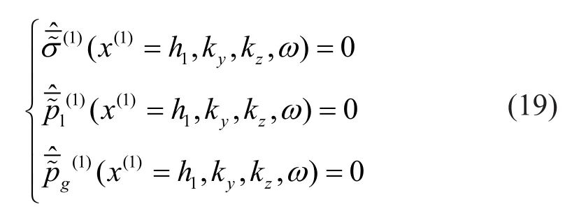
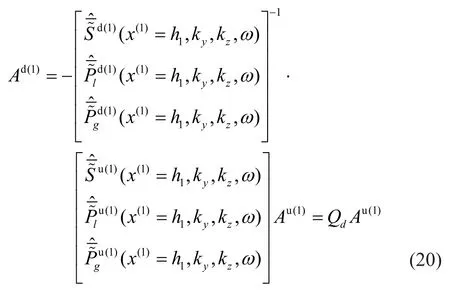
Substituting Eq.(15-1) into Eq.(19), the relationship betweenAd(1)andAu(1)can then be written as:
2.4.2 Model bottom
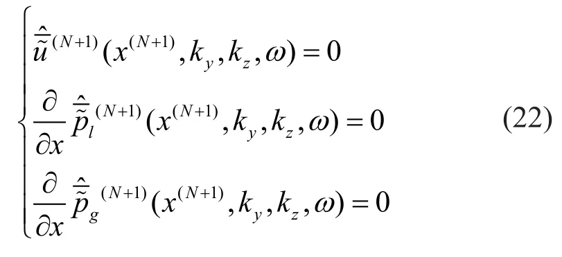
According to the boundary and interface assumption(2), two cases of the bottom boundary of the model can be discussed.If the bottom boundary is a semi-infinite space, the displacement, stress, and pore pressure dissipate to 0 at infinite distance, resulting in:

If the bottom boundary is bedrock, the displacement at the interface between bedrock and the soil layer is 0;the interface is impervious to water and air, resulting in:
2.4.3 Interface between soil layers
In this model, the interface between two adjacent soil layers can be divided into two types.
(i) For the non-tunnel soil layers (n<Nt- 1 andn>Nt),there are only two horizontal interfaces (sn-1andsn).According to assumptions (3), the continuity conditions of displacement, stress, pore pressure, and seepage should be satisfied at these interfaces, leading to the following equation:
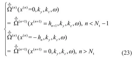
Then, according to Eq.(23), the recursion Eq.(24)can be obtained by:
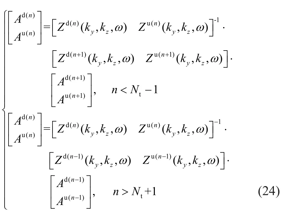
The relationship of the coefficient matrix between adjacent soil layers can be established using the recursion Eq.(24).
Combined with Eqs.(20)-(22) of the ground surface boundary and the bottom boundary, the relationship between the internal coefficient matrices of the (Nt-1)th layer and the (Nt+1)th layer can be obtained as:

(ii) For the tunnel soil layer (n=Nt), there is a horizontal up interface (sn-1) and a down interface(sn).To realize the coupling of the model at these two soil interfaces, the total wave field expression should be unified in the Cartesian coordinate system.By substituting Eq.(17) for Eq.(15-2), the expression of the displacement, pore pressure, and stress components in the Cartesian coordinate system can be written as:
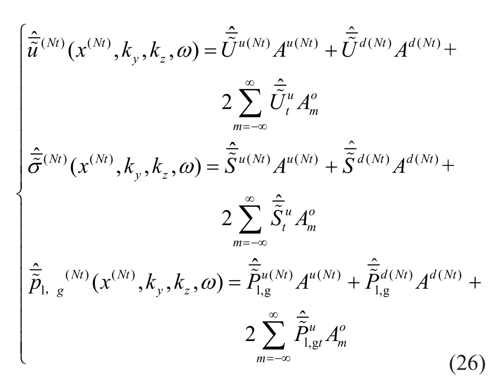
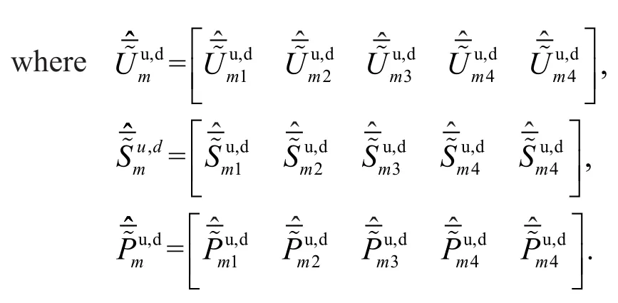
According to the assumptions (3), the displacement,stress, pore pressure, and seepage at the up horizontal interface of theNtth soil layer are continuous; hence, the following equations can be obtained:
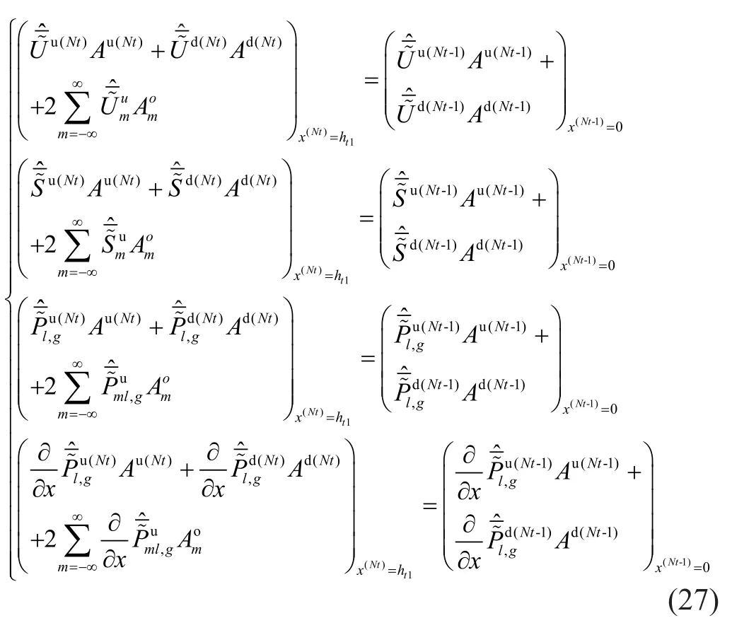
By substituting Eq.(25) for Eq.(27), the following equation can then be obtained:

Similarly, for the down horizontal interface of theNtth soil layer, the displacement, stress, pore pressure,and seepage are continuous, resulting in the following equations:
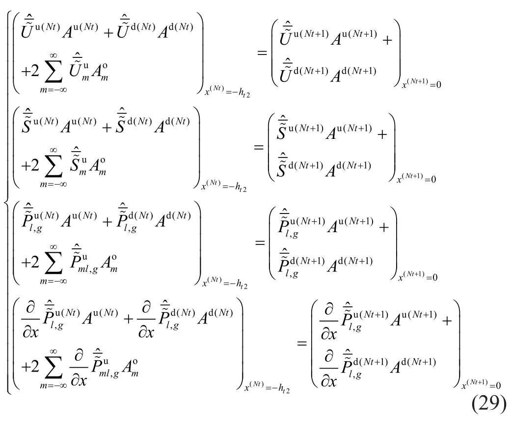
By substituting Eq.(25) into Eq.(29), the following equation can then be obtained:

2.4.4 Interface between tunnel and soil
Because the tunnel and soil interface is a cylindrical surface, to realize the coupling of the model, the total wave field expression should be unified in a cylindrical coordinate system.
Combining Eqs.(28) and (30), the transformation relationship between unknown coefficients in Cartesian coordinates and cylindrical coordinates can be obtained:

This can be written as:

By substituting Eqs.(18) and (32) for Eq.(15-2), the expression of displacement, pore pressure, and stress components in a cylindrical system can be written as:
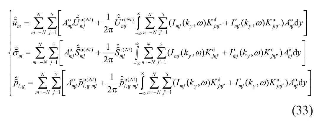
According to the continuity conditions of displacement and stress in the soil and tunnel interface,as well as the governing equation for the shell in Eq.(16),the following equation can be obtained:
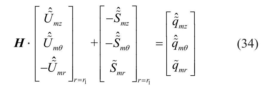
where the origin of the negative signs in Eq.(34) is related to the differences between the systems of coordinates chosen for the tunnel and soil (Forrest and Hunt, 2006).
The condition of imperviousness to water and air can be written as:

By substituting Eq.(33) for Eq.(35), the derivatives of Eq.(35) can be calculated analytically.By combining Eq.(34) and Eq.(35), the unknown coefficientcan be obtained.After substitutingfor Eq.(24) and Eq.(32), the unknown coefficientsAd(n),Au(n)can then be obtained.The dynamic response of the system in the frequency-wavenumber domain can be obtained by substituting,Ad(n),Au(n)for Eq.(15).Finally,the dynamic response of the system in the time-space domain can be obtained by employing the double inverse Fourier transform.
The computation of a (semi)-analytical solution can be realized via numerical operation.The discrete Fourier transform (DFT) was calculated using a spacing step of Δz=1 m and a total number of points ofNz=524.The mode number of 21, which can reach satisfactory convergence, is used (N=10).Calculating the same condition as Husseinet al.(2014), the computation time is approximately 1 s each for frequency (ω) and wave number (kz), whereas the computation time of the extended PiP model and the coupled FE-BE model for each frequency and wavenumber are approximately 5 s and 100 s, respectively, which indicates that the proposed model has high computational efficiency.
3 Numerical results and discussion
3.1 Validation of the proposed model
To validate the reliability of the proposed model, the dynamic responses of tunnel-soil coupling characteristics and the layered characteristics of foundation soil are compared with that of existing models (Husseinet al.,2014; Guoet al., 2020).The schematic diagram of verification is shown in Fig.2.The units in all three directions (x,y,z) in Cartesian coordinates are in meters.The calculation parameters for the tunnel, pore water,and air are those given by Guoet al.(2020), which also are shown in Tables 1 and 2.The other soil calculation parameters for each validation model are derived using the parameter degradation method outlined in Section 2.3.
3.1.1 Degradation for unsaturated porous medium
As previously mentioned, the total wave field expression for unsaturated porous soil can be reduced to single-phase and saturated porous soil by parameter degradation.Therefore, the existing unsaturated soil model is used to verify the reliability of the tunnel-soilcoupling of the proposed model.As shown in Fig.2(a),the tunnel is embedded in an unsaturated half-space consisting of a three-phase medium, and the buried depth of the tunnel is 10 m.The calculation parameters for the soil are shown in Table 3.The response of the soil-tunnel system subjected to a harmonic point load acting on the tunnel invert was calculated using the proposed model.The displacement responses at observation points (10,0, 0) and (-3, 0, 0) were taken to compare them with the results calculated using an existing model (Guoet al.,2020), as shown in Fig.3.The results are consistent.
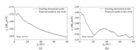
Fig.3 Comparison of displacement amplitudes of a harmonic point load acting on the tunnel invert, as computed with the proposed model and an existing model of a homogeneous unsaturated soil foundation: (a) ux at the point (-3, 0, 0); (b) ux at the point (10, 0, 0)
3.1.2 Degradation for single-phase elastic layered foundation
To further validate the layered characteristics of the proposed model, it is compared with the existing 2.5D coupled FE-BE model with a single-phase elastic layered foundation (Husseinet al., 2014).The comparison results summarized in the following two cases were used to verify the model.
(i) A case study of layered half-space (see Fig.2(b)):The tunnel was embedded in a layered half-space foundation, and the buried depth of the tunnel was 20 m.The calculation parameters of the layer foundation soil are shown in Table 4.The vertical displacementuxof the observation point at ground surface (20, 20, 0) was calculated using the proposed model to compare it to that of the exiting model when the thickness of the overlying soil is 5 m or 10 m, as shown in Fig.4.
(ii) A case study of a soil layer overlying on bedrock(see Fig.2(c)).The tunnel was embedded in a soil layer overlying bedrock, and the buried depth of the tunnel was 20 m.The calculation parameters for the overlying soil layer are taken as those of the second layer, shown in Table 4.The vertical displacementuxof the observation point at the ground surface (20, 20, 0) was calculated and compared to that of the exiting model when the thickness of the overlying soil is 25 m or 30 m, as shown in Fig.5.

Fig.2 Verification cases: (a) homogeneous medium foundation; (b) two-layered half-space foundation; (c) a soil layer overlying bedrock
From Fig.4 and Fig.5, it is evident that the results calculated by the proposed tunnel model in this study are consistent with those of the exiting tunnel models,verifying the reliability of the proposed model in these cases.
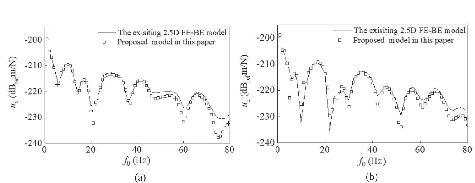
Fig.4 Comparison of displacement amplitudes at the point (20, 20, 0) subjected to a harmonic point load acting on the tunnel invert, as computed with the proposed model and the existing 2.5D coupled FE-BE model of single-phase elastic layered foundation: (a) h1=5 m; (b) h1=10 m
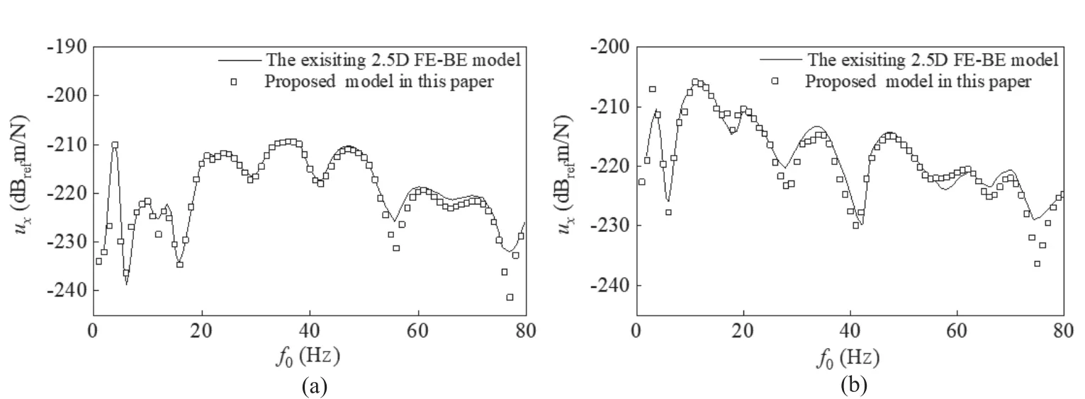
Fig.5 Comparison of displacement amplitudes at the point (20, 20, 0) subjected to a harmonic point load acting on the tunnel invert, as computed with the proposed model and the existing 2.5D coupled FE-BE model of a tunnel situated in a soil layer overlying bedrock: (a) hd=25 m; (b) hd=30 m
3.2 Application of the model: case studies
In saturated soft soil areas, the soil layers near the ground surface are often unsaturated for various reasons, such as transpiration and groundwater resource development.However, existing tunnel models consider this soil as either homogeneous saturated soil or unsaturated soil, which cannot reliably predict the dynamic response of a saturated foundation covered with an unsaturated soil layer.Therefore, in the following section, the proposed model is used to analyze the differences in the dynamic response of a homogeneous saturated foundation, homogeneous unsaturated foundation, and saturated foundation with overlying unsaturated soil.Five case studies are discussed with different saturations of soil layers, as shown in Table 5.The depth of the tunnel (d) is 10 m and the thickness of the overlying soil layer (h1) is assumed to be 5 m.The calculation parameters in (Guoet al., 2020) also are used for case analysis, as presented in Tables 1-3.
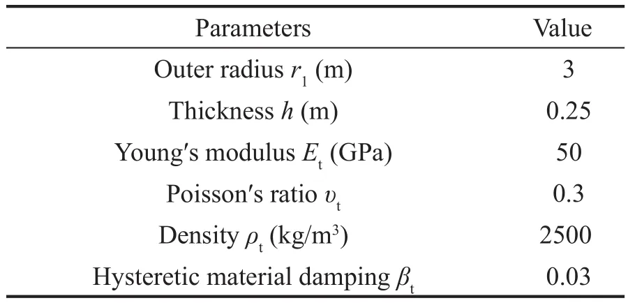
Table 1 Tunnel parameters
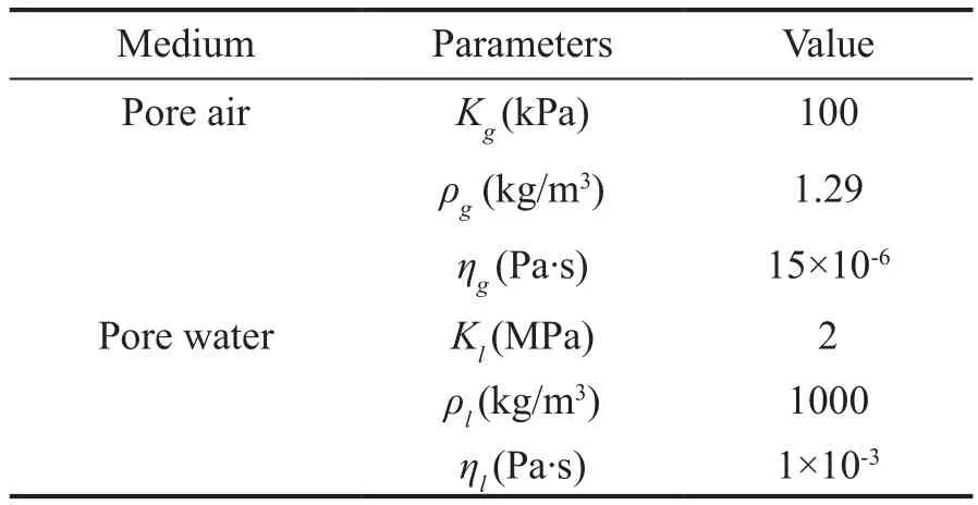
Table 2 Pore fluid parameters
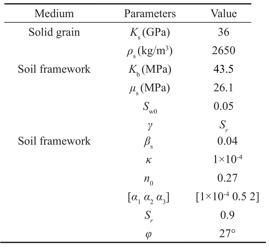
Table 3 Parameter value of unsaturated soil
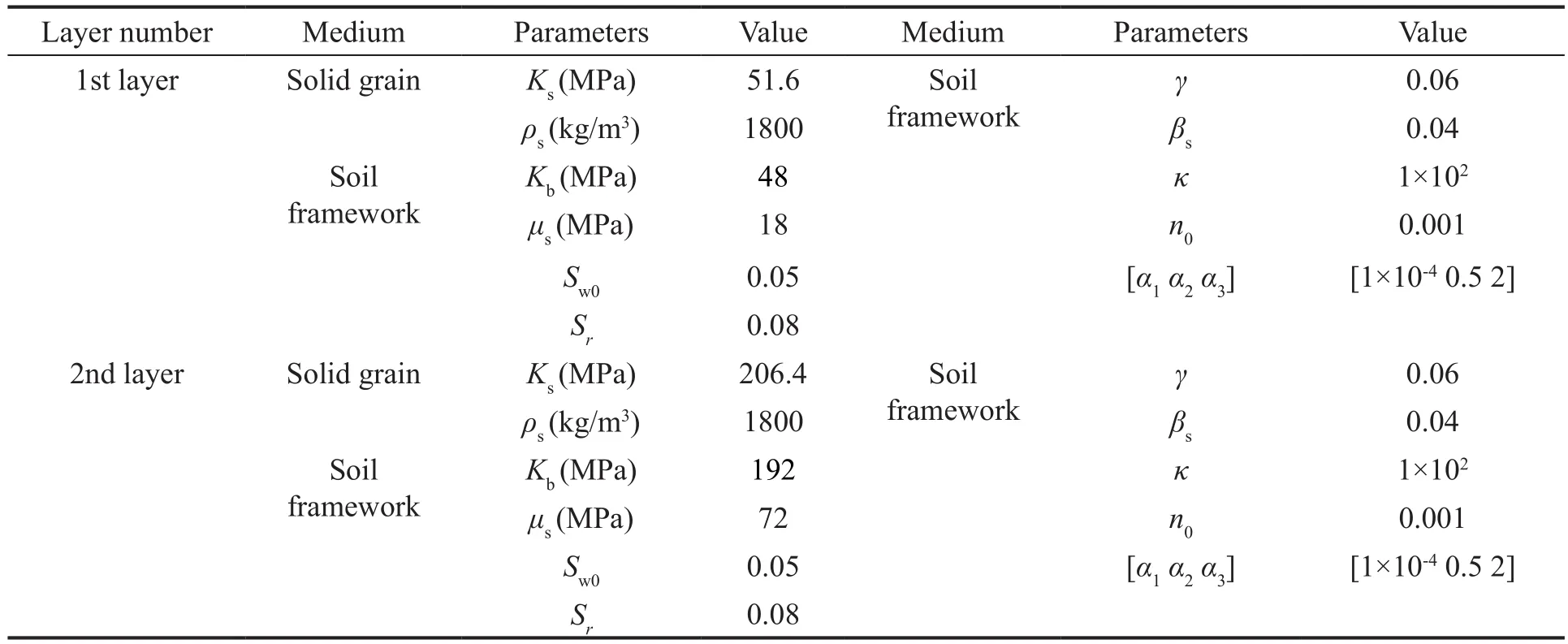
Table 4 Soil parameters degenerated to single-phase medium

Table 5 Saturation of foundation soil layers in different cases
Figure 6 presents the magnitudes of vertical displacement, normal stress, and pore water pressure of the soil at the plane ofx=0 when the tunnel invert is subjected to a harmonic point with a 20 Hz load in three cases (Case 1, Case 2, and Case 4).First, we notice that the system dynamic responses of the saturated porous
medium foundation (Case 1) and unsaturated porous medium foundation (Case 4) are different.There are two main reasons for this observation: i) The dynamic shear modulus of soil increases with decrease in saturation,which mainly affects dynamic response amplitude.ii)The wavelength of the elastic wave in soil increases with a decrease in saturation, which mainly affects dynamic response distribution.In addition, there is a clear difference in pore water pressure between these two cases because the bulk modulus of air is far lower than that of liquid; hence, with an increase in gas content,excess pore water pressure decreases rapidly.
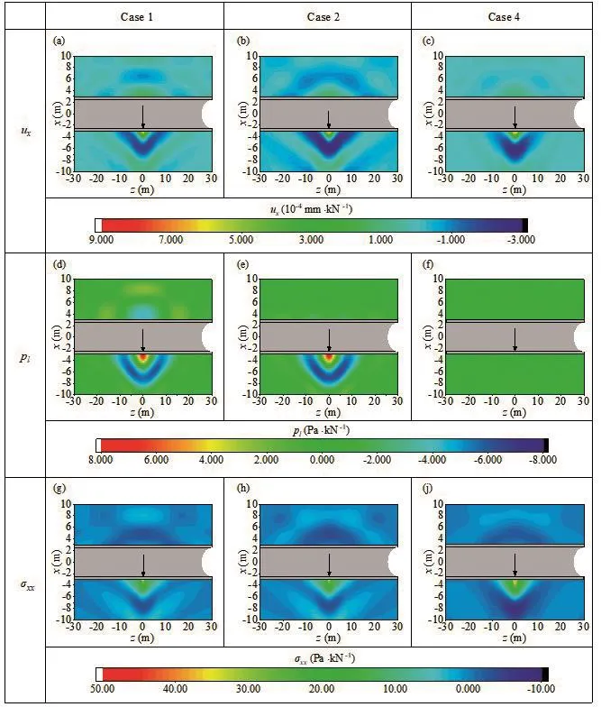
Fig.6 Vertical displacement ux, normal stress σxx, and pore water pressure pl of the soil at the plane of x=0 when the tunnel invert is subjected to a unit stationary harmonic load with 20 Hz at (x, y, z)=(-2.75, 0, 0) in different cases
Figure 6 also shows that the dynamic response of a saturated foundation with overlying unsaturated soil(Case 2) is different from that of a saturated porous medium foundation (Case 1) and an unsaturated porous medium foundation (Case 4).This is because of a new scattering surface that appears at the interface between the saturated and unsaturated medium due to their different properties.This surface changes the propagation characteristics of elastic waves (reflection,refraction) and the seepage conditions of the total foundation, thus making the dynamic response different.Therefore, to better evaluate the dynamic response of the tunnel system, the layered characteristics and saturation of different soil layers should be considered in the modeling.
To further analyze the influence of the existence of an overlying unsaturated layer on the dynamic response,the dynamic responses of three types of foundation soils are compared: homogeneous saturated foundation (Case 1), homogeneous unsaturated foundation (Cases 4 and 5), and saturated foundation with overlying unsaturated soil (Cases 2 and 3).Two observation points on the ground surface ((10, 0, 0), (10, 20, 0)), one observation point in the soil (-3, 20, 0), and one observation point at the tunnel bottom (-3, 0, 0) were selected for analysis.
Figure 7 presents the magnitudes of verticaldisplacement versus frequency of the four observation points when the tunnel invert is subjected to a harmonic point.Figures 7(a), 7(b), and 7(d) show that the dynamic displacement responses of the same types of foundation(Cases 2-5) are similar, as the number of scattering surfaces is the same and the characteristics of wave propagation are similar.As for the saturated foundation with overlying unsaturated soil (Cases 2 and 3), a new scattering surface appears at the interface between the saturated and unsaturated medium, causing a dynamic response different from that of the homogeneous saturated foundation (Case 1) or the homogeneous unsaturated foundation (Cases 4 and 5) under different load excitation frequencies.
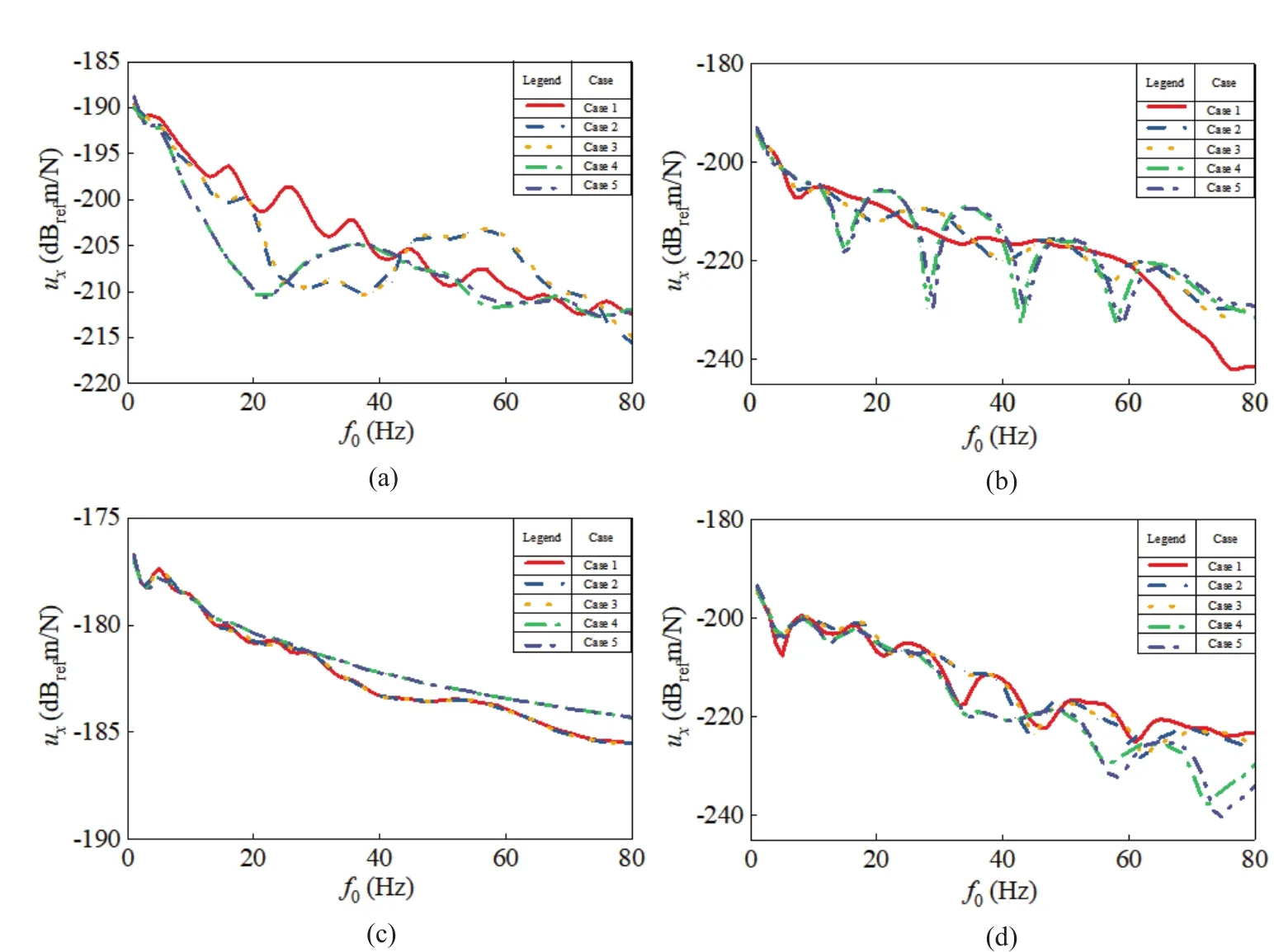
Fig.7 Vertical displacement ux varies with load frequency when the tunnel invert is subjected to a unit stationary harmonic load at (x, y, z)=(-2.75, 0, 0): (a) observation point at (10, 0, 0); (b) observation point at (10, 20, 0); (c) observation point at(-3, 0, 0); (d) observation point at (-3, 20, 0)
Figure 7(c) also shows that the dynamic displacement responses of the tunnel bottom in Cases 1-3 are similar,as are the responses in Cases 4 and 5, which means that this response is mainly affected by the characteristics of the soil layer in which the tunnel is situated.
Figure 8 presents the magnitude of normal stress and pore water pressure versus load frequency at two observation points ((-3, 0, 0), (-3, 20, 0)) when the tunnel invert is subjected to a harmonic point.Figures 8(a)and 8(b) show that the magnitudes of vertical stress and pore water pressure of the soil at the tunnel bottom are mainly affected by the characteristics of the soil in which the tunnel is situated, which is rarely affected by the existence of overlying unsaturated soil.However, as shown in Figs.8(c) and 8(d), regarding the observation in the soil foundation (-3, 20, 0), there are noticeable differences between the three types of foundation,meaning that soil saturation and the existence of a new scattering surface at the interface between the different media affect the responses of normal stress and pore water pressure in soil foundation.
We also analyzed the influence of the thickness of the overlying unsaturated layer on the dynamic response of the tunnel-layered soil system.The thickness in Case 2 was changed for comparative analysis, whereas the buried depth of the tunnel remained the same to render the sourcereceiver distances unchanged.Figure 9 presents the vertical displacement response under different thicknesses of the overlying layer.As shown in Figs.9(a), 9(b), and 9(d),the magnitudes of vertical displacement under different thicknesses are markedly different, as the overlying layer affects the location of the new scattering surface,in turn affecting the vertical displacement.Conversely,Fig.9(c) indicates that the vertical displacement of the tunnel bottom does not change with the thickness of the overlying layer, which demonstrates that the vertical displacement of the tunnel bottom is rarely affected by the overlying layer.
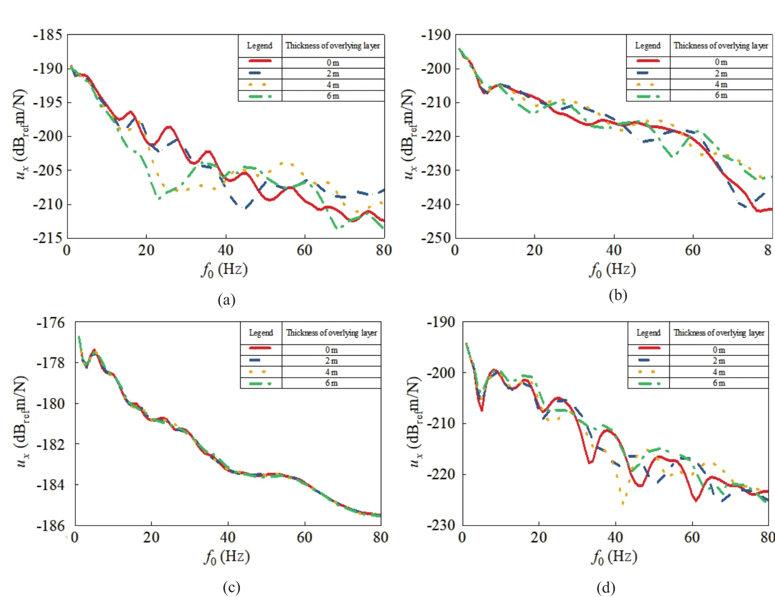
Fig.9 Vertical displacement ux varies with load frequency when the tunnel invert is subjected to a unit stationary harmonic load at (x, y, z)=(-2.75, 0, 0) under different thicknesses of the overlying layer: (a) observation point at (10, 0, 0); (b) observation point at (10, 20, 0); (c) observation point at (-3, 0, 0); (d) observation point at (-3, 20, 0)
Figure 10 presents the magnitudes of vertical stress and pore water pressure under different thicknesses of the overlying layer, indicating that they are different at the soil foundation, whereas those at the tunnel bottom are not affected.
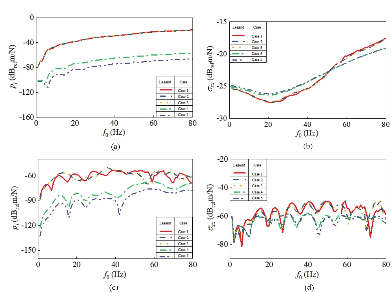
Fig.8 Dynamic normal stress and pore water pressure response varies with load frequency when the tunnel invert is subjected to a unit stationary harmonic load at (x, y, z)=(-2.75, 0, 0): (a/b) observation point at (-3, 0, 0); (c/d) observation point at (-3, 20, 0)
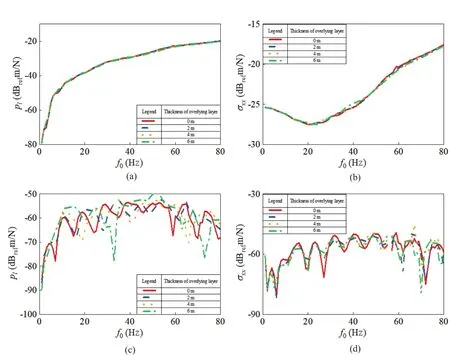
Fig.10 Dynamic normal stress and pore water pressure response varies with load frequency when the tunnel invert is subjected to a unit stationary harmonic load at (x, y, z)=(-2.75, 0, 0) under different thicknesses of the overlying layer: (a/b) observation point at (-3, 0, 0); (c/d) observation point at (-3, 20, 0)
4 Conclusions
(1) An analytical model was proposed to investigate the dynamic response of a tunnel embedded in layered media.The proposed model was validated by comparing it to existing tunnel models.This analytical model has high computational efficiency and can better simulate realistic soil conditions, such as the coexistence of single-phase soil, two-phase saturated soil, and threephase unsaturated soil.
(2) The saturation of soil layers has a great effect on the dynamic response of a tunnel layered soil system.New scattering surfaces appear at the interfaces between layers, consisting of different media (a singlephase medium, a saturated porous medium, or an unsaturated porous medium), changing the propagation characteristics of elastic waves, such as reflection and refraction, as well as the seepage conditions of the foundation.Therefore, it is necessary to consider the layered characteristics and saturations of the soil in the evaluation of the dynamic response of a tunnel layered soil system.
(3) For an underground railway tunnel embedded in a saturated foundation covered by an unsaturated soil layer, both the existence of the overlying unsaturated layer and the thickness of this layer have a great effect on the magnitudes of the dynamic displacements of the soil at the ground surface.However, the thickness of the overlying unsaturated soil and the variations in saturation rarely affect the dynamic response of the soil at the tunnel bottom, which is mainly affected by the characteristic of the soil in which the tunnel is situated.
Acknowledgment
The study on which this paper is based was supported by the National Natural Science Foundation of China under Grant No.51808405.
杂志排行
Earthquake Engineering and Engineering Vibration的其它文章
- Property estimation of free-field sand in 1-g shaking table tests
- Dynamic p-y curves for vertical and batter pile groups in liquefied sand
- Underground blast effects on structural pounding
- Controlled rocking pile foundation system with replaceable bar fuses for seismic resilience
- Seismic ground amplification induced by box-shaped tunnels
- Shaking table test of subgrade slope reinforced by gravity retaining wall with geogrids
