Ion-focused propagation of a relativistic electron beam in the self-generated plasma in atmosphere
2022-06-29JianHongHao郝建红BiXiXue薛碧曦QiangZhao赵强FangZhang张芳JieQingFan范杰清andZhiWeiDong董志伟
Jian-Hong Hao(郝建红) Bi-Xi Xue(薛碧曦) Qiang Zhao(赵强)Fang Zhang(张芳) Jie-Qing Fan(范杰清) and Zhi-Wei Dong(董志伟)
1School of Electrical and Electronic Engineering Department,North China Electric Power University,Beijing 102206,China
2Institute of Applied Physics and Computational Mathematics,Beijing 100094 China
Keywords: ion-focused regime (IFR), charge neutralization, electron avalanche, relativistic electron beam(REB),particle-in-cell Monte Carlo collision(PIC-MCC)
1. Introduction
During long-range propagation of an artificial relativistic electron beam(REB)in space environment,multiple practical applications in active space experiments can be achieved by probing secondary particles of interactions between primary beam electrons with ambient neutrals,including tracing magnetic field lines and analyzing beam–particle interactions.[1–5]Due to strong space charge effects of intense REBs, it is difficult to achieve long-range propagation in the order of several hundreds of kilometers in vacuum. In addition,owing to degradation of beam quality,REBs are unable to meet need of practical applications after long-range propagation.Therefore,how to increase beam transport efficiency in low-pressure atmosphere during long-range propagation has always been the focus of associated research.[6]As the ambient neutral density of atmosphere varies in a complicated manner at different altitudes,propagation properties of REBs can be affected by multiple factors.Previous studies have discussed long-range propagations of REBs in atmosphere from different perspectives thoroughly.[7–12]We also gave the Monte–Carlo(MC)simulation,particle-in-cell(PIC)simulation and theoretical study on the influence of ambient neutral density, intensity and direction of geomagnetic field, and the ion channel oscillation on the long-range propagation of REBs.[13–15]
After emission of an REB into low-pressure atmosphere environment, the impact ionization between primary beam electrons and ambient particles produces positive ions and secondary electrons in the beam.Under the influence of Coulomb repulsion, secondary electrons in the beam will be expelled transversely and the heavier positive ions will be left on the beam path. Accordingly, an ion-focused regime (IFR) is established. In the low-pressure atmosphere, ambient particle density varies at a relatively slow rate, meaning that the IFR could maintain for a longer time in such environment. The IFR also has multiple applications in devices such as plasmaassisted microwave sources.[16–24]However,the REB and ambient neutral gas require to fulfill some conditions for generation of an IFR.Previous studies indicated that in neutral gas with a relatively low pressure, it is impossible to accumulate enough positive ions for the self-focused propagation of an REB in a short period of time. In the neutral gas with a relatively high pressure,the amounts of both secondary electrons and ions increase rapidly,leading to accumulation of multiple secondary electrons in the beam. Such a phenomenon may lead to various instabilities,including the two-stream instability and resistive hose instability,which will result in a significant decrease in the beam propagation efficiency.[25,26]Therefore, it is necessary to provide a more detailed description of the connection between physical characteristics of the IFR and parameters of REBs.Studies mentioned above mainly concentrated on device physical problems, such as the propagation of REBs in an enclosed environment. Under such conditions,transverse velocity of secondary electrons will be lost at the drift tube wall. However, for the REB which propagates in an open environment such as the Earth atmosphere,secondary electrons are able to move transversely to a further position and a reverse return current will be generated on the surface of the beam. In PIC simulations, this difference should be taken into account by setting appropriate boundary conditions and dimensions of the simulation region. For the longitudinal motion of secondary electrons in the beam and other complex physical processes,associated analytical studies typically neglect these effects for ease of calculation. A PIC simulation code can take into account the influence of more physical fields, thus a particle-in-cell Monte Carlo collision(PICMCC)method is used in this study to calculate the propagation of REBs in low-pressure neutral gas and to analyze characteristics of the IFR generated by the beam.
In the present study, our aim is to explore the possibility of long-range propagation of REBs by utilizing the IFR in the atmosphere. First, the basic physical processes during long-range propagation of REBs and envelope equations of the sheet beam are briefly introduced in Section 2. Long-range propagation of REBs in low-pressure neutral gas is numerically investigated by using a PIC-MCC code. The establishment of IFR and the corresponding influence on the long-range propagation of REBs are analyzed by combination with associated theories. Finally, possible solutions for the realization of long-range propagation of REBs in the atmosphere are discussed.
2. The calculation model
2.1. Collision processes and physical model
2.1.1. Electron impact ionization and electron avalanche
In accordance with previous studies, parameters of the REB and neutral gas used in this study are listed in Table 1.Neutral gas is composed of 70%of N2and 30%of O2to simulate the Earth atmosphere. During the propagation of the REB in the neutral gas, gas atoms become ionized because of collisions with beam electrons and ions,and secondary electrons are produced. In the impact ionization,the ion density can be modeled as[26]

whereniandnbare the densities of ions and beam electrons,respectively;tbis the propagation time of the beam after it is injected into the gas, andτeis the characteristic electron impact ionization time expressed as follows:

Note thatngis the density of neutral gas;σbis ionization crosssection;vis the velocity of electrons. Ionization time of the REB with parameters in Table 1 is approximately 1ns, which is much less than the longitudinal and transverse ion oscillation time.Thus,ions can be considered immobile in this study.

Table 1. Physical parameters of the beam and plasma.
2.1.2. Electron avalanche
After the ionization between beam electrons and neutral gas atoms, secondary electrons will be accelerated and expelled transversely out of the beam by the REB.Motion of secondary electrons will lead to further ionization of background gas,which can be expressed by
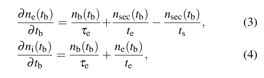
wherensecis the density of secondary electrons;teandtsare the effective electron avalanche time and the effective secondary escape time, respectively. Before the beam is totally charge neutralized,tsbecomes relatively small, which means that secondary electrons will quickly escape from the beam transversely. In this case, electron avalanching effects can be usually neglected.
2.2. The PIC-MCC model
Compared to the previous PIC research on the beam transportation in an enclosed environment, the present study is mainly concentrated on the influence of IFR on the REB dynamics in the atmosphere environment. Without any shielding boundaries in low-pressure neutral gas,it has been proved that the significant presence of numerical noise may result in decrease of the calculation accuracy in a fully electromagnetic model. Considering the cost in computational capacity when calculating the long-range propagation, a PIC-MCC quasielectromagnetic model in the so-called 2D3V (2D in spatial and 3D in velocity)formulation is used to simulate the propagation of the REB in neutral gas. A snapshot of PIC-MCC simulations is shown in Fig.1,whereLxandLyare the transverse and longitudinal dimensions. In addition, the moving window technology is employed in PIC simulations to meet the need in propagation distance of the beam,whereas a cylindrical coordinate system cannot be collocated with the moving window. Therefore, a two-dimensional Cartesian coordinate system is set to depict the particle distribution, in which thexandyaxes are along the propagation direction and transverse direction of the REB, respectively. Thezaxis is auxiliary direction. A sheet beam model is used accordingly.The beam electrons are uniformly distributed in space, and the beam is infinitely long in the longitude direction. Fromtb=0,the beam is continuously emitted from the left boundary(x=0)along the positive direction ofx-axis, which indicates thattbcorresponds to the beam propagation time. The beam parameters are listed in Table 1. The total size and grids of the simulation satisfy the Courant–Friedrichs–Lewy(CFL)condition.[27]At the left boundary, we use a Dirichlet (i.e.,conducting) boundary condition on the electrostatic potentialψx=0=0. At the right boundary,we use a Neumann boundary conditionψ′x=Lx=0. The top and bottom boundaries are set to be periodic.

Fig. 1. Snapshot of simulation particle positions: (a) distribution of beam electrons and secondary ions, (b) distribution of beam electrons and secondary electrons.
To investigate the collisions between particles, a Monte Carlo collision technique is used, including the following reactions: (1)beam electron,secondary electron impact ionizations
(2)beam electron,secondary electron elastic collisions

(3)beam electron,secondary electron attachments

Ionization cross sections of low-energy electrons (E <10 keV) are obtained from experiments, and the cross sections of high-energy electrons(E >10 keV)are calculated by Coulomb collision cross section.[28,29]In the PIC-MCC simulations, “macroparticles” represent several particles whose physical characteristics are close to each other. During the long-range propagation, electron avalanche can lead to a dramatic increase of secondary electrons, which further results in a massive reduction of computational speed. Null reactions“combination”can decrease the amount of the macroparticles in the area with a high particle density by increasing the weights of the macroparticles. In this way, the computation efficiency and ensuring precision can be improved to satisfy the need of our calculation.
2.3. The analytical model
The envelope equations in the paraxial axial approximation can describe the envelope variations of REBs during longrange propagation. If the energy loss caused by the beam–atmosphere collisions is ignored,envelope equations of a sheet beam can be written as[30]

whereIbandIpare the beam current and return current,respectively.Previous studies usually assume that the beam is charge neutral and the current neutralization is negligible. In order to analyze the influence of beam neutralization on the long-range propagation,neutralization factors,which vary with propagation time and longitudinal positions, are obtained in accordance with the data in PIC simulations. By taking neutralization factors into envelope equations,the results can be verified by comparing the PIC results with the results obtained by envelope equations.
3. Charge and current neutralizations in IFR
3.1. Charge neutralization
Establishment processes of IFR can be described by the transverse velocity variations of secondary electrons at different propagation timetb. Figure 2 shows the transverse velocity variations of secondary electrons whentb=9 ns andtb=57 ns. In Fig. 2(a), as the beam propagates for a short time,the beam has not been totally charge neutralization.Most secondary electrons are expelled transversely by the beam. At this time, most secondary electrons located at the positiveyaxis transport along the positive direction or conversely.Whentb=57 ns,beam body of the REB has been totally charge neutralization,leading to the accumulation of excess positive ions in the beam. These ions can effectively restrict the radical motion of newly generated secondary electrons, or even pull the other secondary electrons back to the beam to neutralize the beam. Consequently, transverse velocities of secondary electrons are more homogenously distributed along theyaxis with a much smaller peak amplitude,as depicted in Fig.2(b).

Fig. 2. Transverse velocities of secondary electrons at different transverse positions: (a)tb=9 ns,(b)tb=57 ns.
Distribution of the REB is shown in Fig.3 and densities of various particles in the beam are shown in Fig.4. At the beam head, as the duration of impact ionization is relatively short,density of secondary particles is lower than beam electrons,which indicates that the IFR has not been well established.The beam expands transversely under the influence of space charge effects and initial emittance, resulting in a density of beam electrons lower than the initial density. As the coordinatexdecreases, the duration of impact ionization improves gradually, leading to the increase of secondary particle densities. Furthermore, in accordance with Eq. (6),feincreases with the ion densityni.At the beam neck,whenfesatisfies the so-called Budker condition,i.e.,fe>1/γ2,the corresponding phenomenon called Bennett pinch occurs because of the transverse pinch force supposed by the IFR.The transverse dimension can be reduced to initial size gradually. At the junction part between the beam neck and beam body,the beam can be over pinched(fe>1). The significantly over pinched part of the beam may even break up, which eventually interrupts the efficient beam propagation. In the region of beam body,densities of various secondary particles exceed the beam electron density and the transverse dimension of the beam is close to the initial size,which indicates that the IFR has been fully established.
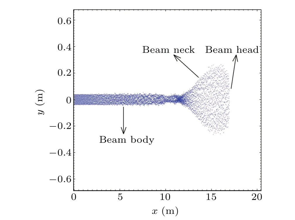
Fig.3. Distribution of the REB when tb=57 ns.

Fig.4. Relationship between the densities of various particles and longitudinal positions.
3.2. Current neutralization
During the long-range propagation of the REB in the plasma environment, a longitudinal electric fieldEzis generated by net currentInetnear the beam. The return currentIp,which flows in opposite directions against the beam,is driven byEz;le=c/ωpis the so-called electromagnetic skin depth,which is also the thickness of the sheath near the edge of the beam to which the net currentIpis confined;[31,32]ωpis the plasma frequency. The relationship between the skin depthleand the transverse dimension of the REB can be modeled as[33]

Variations of the above currents in PIC-MCC simulations are shown in Fig.5,whereInet=Ib+Ip. At the front of the beam head,beam electrons are accelerated because of the longitudinal space charge effects of other beam electrons,and the first peak beam current is formed. In the beam neck area,with the Bennett pinch of the REB, beam density increases gradually with the decrease of the coordinatexof the beam electrons,and finally the second peak of beam current is formed. In the connection area between the beam neck and beam body, the beam current gradually approaches the initial beam current.During the above processes of the change in beam current,the return current is generated by the motion of secondary electrons to suppress the effect of beam current variation on generated plasma environment. The return currentIpcan be written as[32]

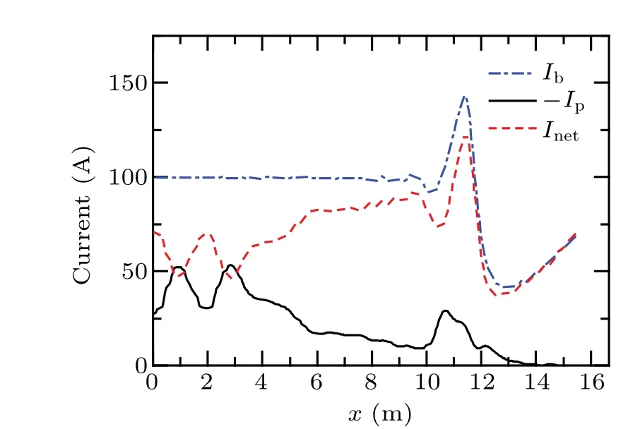
Fig.5. Variations of Ib,-Ip,and Inet in the beam.
Previous studies use the electric diffusion time of the plasma to describe the growth period of return current,which can be written as[31]
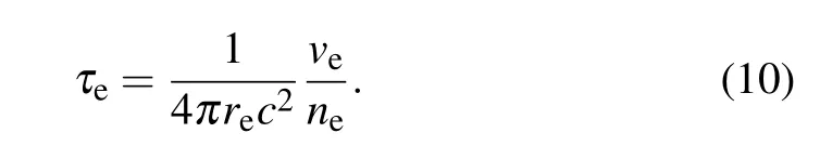
Here,reis the classical electron radius,andveis the effective collision frequency which can be estimated by the formula[34]

wherengis the density of neutral gas. Figure 6 shows the variation ofτewith the propagation time. With the increase oftb, transverse and longitudinal dimension of the beam increase because of the space charge effects. Thus, the density of beam electrons decreases. Reduction ofneleads to the increase ofτe. This regularity can be shown both in PIC-MCC simulations and the analytical model.

Fig.6. Variation of τe with the propagation time tb.
The formulas of the two neutralization factors are given as Eqs. (6) and (7). Combined the densities of various particles and distributions of various currents in Figs. 4 and 5,variations of neutralization factors with longitudinal positions are shown in Fig. 7. During the long-range propagation of a 1 MeV REB in neutral gas of 10 Pa,impact ionizations between the beam and ambient particles make the charge neutralization factor beyond the Budker condition in a short duration(<1 ns)and reach its peak in the connection area between the beam neck and beam body. Ions and secondary electrons in the beam change the value offevarying around 1 in the beam body, which means that the subsequent part of the beam is totally charge neutralized. Under the influence of the longitudinal motion of both beam electrons and secondary electrons,fmreaches its maximum at the tail of the beam.
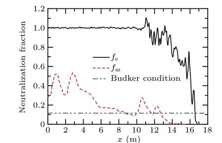
Fig.7. Variations of neutralization factors fe and fm with the longitudinal positions.
4. Propagation properties of the REB in IFR
4.1. Influence of IFR on the longitudinal motion of the REB
After the REB is emitted into the vacuum or the neutral gas, the distribution of longitudinal velocities of beam electrons shows certain features. This phenomenon is more evident in long-range propagation of REBs,but only a few studies have been focused on such influence of the IFR. Figure 8 shows distributions of longitudinal velocities of beam electrons whentb=15 ns andtb=57 ns.Whentb=15 ns,the duration of impact ionizations between beam electrons and ambient particles is not long enough for the establishment of IFR.Under the influence of longitudinal space-charge effects,beam electrons which are just emitted into the gas will be decelerated by other beam electrons. On the contrary,beam electrons at the front of the beam head are accelerated by other beam electrons. Without the effect of any other external forces,the longitudinal space-charge effects can cause the increase of longitudinal dimension, resulting in a low transport efficiency.Whentb= 57 ns, at the beam head and neck, because the density of ions is not high enough to affect the propagation of REB, distribution of longitudinal velocities in this area is similar totb=15 ns. In the connection area between the beam neck and body,a peak of velocity appears in the position wherefe>1 in Fig.7,which indicates that the excessive ions in the beam attract the beam electrons,leading to the transverse over pinch and longitudinal acceleration. For beam electrons in the beam body, the above discussion in Subsection 3.1 indicates that the beam is neutralized under the influence of IFR,which means that the longitudinal space-charge effects are offset accordingly. Consequently, the longitudinal velocities are close to the initial velocity of the beam.It can be concluded that IFR can neutralize the longitudinal space-charge effects and limit the longitudinal expansion of the beam efficiently. Moreover,combining the previous calculation results,[15]when the REB propagates in the natural plasma environment in the atmosphere,ion channel always continues to oscillate periodically over the entire propagation,leading to the synchronous oscillation of longitudinal velocities of beam electrons. When the beam propagates in the self-generated plasma in neutral gas,as the density of secondary particles varies significantly at different longitudinal positions,the IFR will not oscillate at a certain frequency. Hence,the longitudinal velocity keeps close to the initial velocity,as depicted in Fig.8(b). In these two conditions, although both the ion channel and the IFR can focus the propagation of the REB similarly, amplitude of the longitudinal velocity gradually increases during the long-range propagation in the natural plasma, which eventually leads to significant instabilities as well as a low transport efficiency.This phenomenon does not appear when the REB propagates in the self-generated plasma.

Fig. 8. Distributions of longitudinal velocities of beam electrons: (a)tb=15 ns,(b)tb=57 ns.
4.2. Influence of IFR on the transverse motion of the REB
Comparison of the beam envelopes between PIC-MCC simulations and envelope equations is shown in Fig.9. At the beam head,complicated variations of various particle densities result in the certain fluctuations of charge neutralization factorfe, some errors are expected in the calculated result of envelope equations,while the changing rules of these two methods are consistent. There is an obvious transverse expansion at the beam head. Whenfesatisfies the Budker condition,the transverse expansion of the beam is limited by IFR and the beam envelope gradually approaches the initial value. In the beam body area,beam envelope tends to be stable under the common effects of multiple forces. The equilibrium transverse dimension is close to the initial transverse dimension.
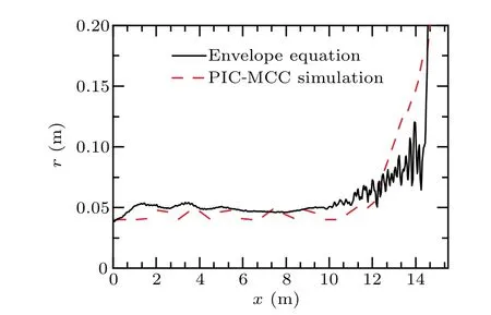
Fig.9. Comparison of beam envelopes calculated by PIC-MCC simulations and envelope equations.
5. Problems faced by the long-range propagation of the REB in the earth atmosphere
5.1. Instabilities of the REB in IFR
According to Section 4, IFR can contribute to the longrange propagation of REB by limiting the transverse and longitudinal expansion. However, after the REB has propagated in neutral gas for a period,electron avalanche appears because of the continuous occurrence of impact ionizations and may disrupt the stable propagation of the REB. Figure 10 shows the distribution of beam electrons whentb= 75 ns. Compared with Fig.3,the obvious transverse and longitudinal expansion can be observed, and a significant instability occurs at the tail of the beam. With the increase oftb, this instability will spread through the entire beam and totally disrupt the propagation. Figure 11 shows the variation of secondary electron densities in different longitudinal positions withtb. The above discussion in Sections 3 and 4 indicates that electron avalanche begins when the beam has finished charge neutralization in the beam body area,resulting in the exponential increase and accumulation of secondary electrons in the beam.Multiple secondary electrons may lead to a two-stream instability with beam electrons and further other instabilities. The increase of secondary electrons also improves the return current as well as the current neutralization factorfm. Current neutralization may weaken the focused effect of IFR and lead to the occurrence of resistive hose instability. Multiple factors mentioned above eventually result in the macro instability in Fig.10.

Fig.10. Distribution of the REB when tb=75 ns.
Combined the results of both theoretical analyses and PIC-MCC simulations, in order to avoid the occurrence of such instabilities, the decrease of pulse width Δtof the REB can be taken into account to reduce the duration of impact ionization at the beam tail.Distributions of REBs from Δt=72 ns to Δt=65 ns whentb=75 ns are shown in Fig. 12. With the decrease of Δt,the influence of electron avalanche recedes gradually. When Δt <65 ns, the effect of electron avalanche at the beam tail can be basically ignored. It can be concluded that reduction of the pulse width can be used to avoid the disruption of beam stability by electron avalanche.
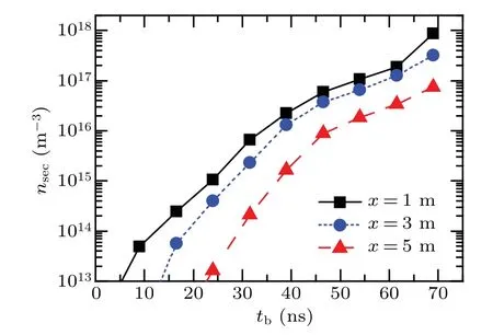
Fig. 11. Variation of secondary electron densities with tb at different longitudinal positions.

Fig. 12. Distributions of REBs when tb =75 ns: (a) Δt =72 ns, (b)Δt=70 ns,(c)Δt=68 ns,and(d)Δt=65 ns.
5.2. Reduction of beam quality during long-rang propagation
As the REB propagates to a longer distance in the neutral gas, beam-atmosphere interactions will significantly reduce the beam quality. Figure 13 presents the beam electron density at the beam head,beam fluence and charge neutralization factorfein the beam body area. Under the influence of impact ionizations,elastic collisions,and space charge effects of the beam, the beam head will expand consistently and the beam electron density decreases correspondingly. As a result,number of ions generated by the beam head is not enough for the establishment of the stable IFR in the beam body. The beam quality reduces gradually, as shown by the decrease of fluence andfe.
A possible solution is to use a train of pulses for longrange propagation in the atmosphere to handle the problem of beam quality and the reduction during long-range propagation.[32]The early emitted pulses are used to generate an IFR in the atmosphere with a similar mechanism to the beam head in the above experience. By sacrificing several early emitted pulses, a stable IFR can be established in space environment and the long-range propagation of other REB pulses may be achieved.
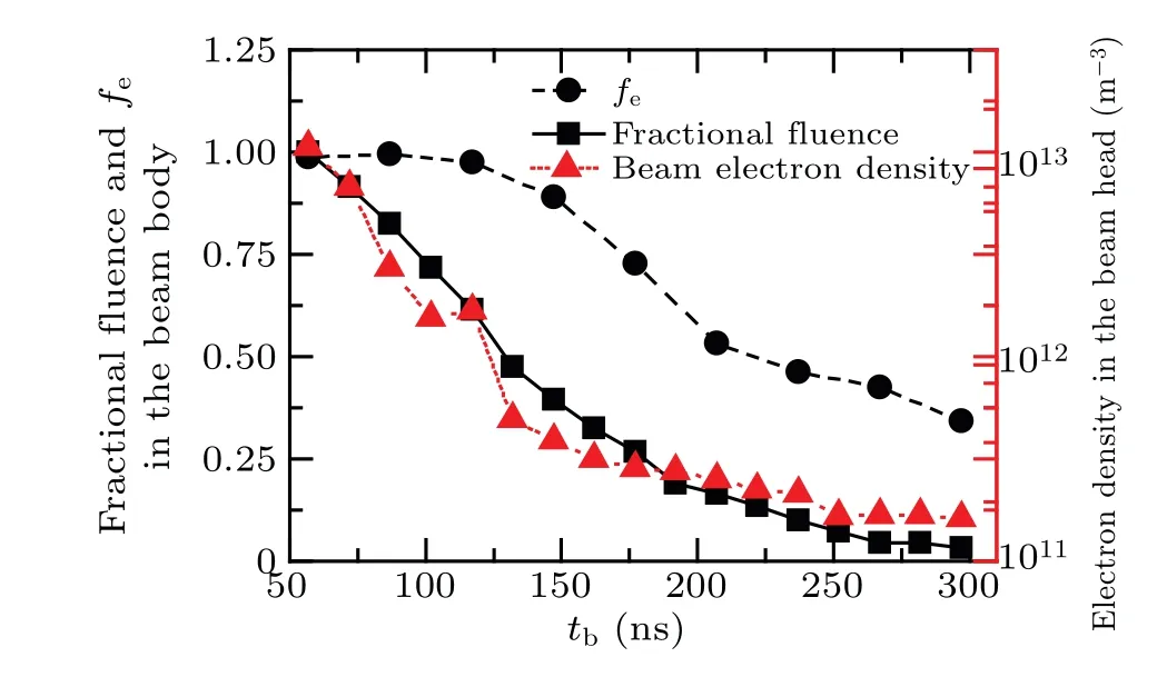
Fig.13. Reduction of beam quality during long-rang propagation.
6. Conclusion
In this study, we mainly focus on the establishment and influence of IFR during propagation of the REB in neutral gas and further explore the possibility of long-range propagation.A PIC-MCC method is used to calculate charge neutralization factorfeand current neutralization factorfm. The result shows that afterfesatisfies the Budker condition, transverse dimension of the beam head which has already expanded will be reduced to the initial size and form the beam neck. The beam may even be over-pinched in the connection area between beam neck and beam body. In the beam body area,the beam can be totally charge neutralized, which indicates that the IFR has been established. The PIC-MCC simulation results show that the beam is well focused by IFR in the beam body. Compared with the propagation of the REB in the natural plasma environment,longitudinal velocities of beam electrons will not oscillate periodically when the beam propagates in the self-generated plasma in neutral gas. However,effect of electron avalanche exacerbates gradually with time after the beam has been totally charge neutralization, leading to a significant current neutralization at the beam tail. Macro instabilities may also occur and interrupt efficient beam propagation. Decrease of the pulse width of the REB can reduce the influence of electron avalanche,whereas the beam quality during long-range propagation may be improved by using a train of REB pulses. Further improvement of beam quality during long-range propagation will be the next step in our study.
In accordance with the results in the present study,it can be concluded that the IFR can effectively limit the transverse and longitude expansion of the REB and improve the transport efficiency during long-range propagation.
Acknowledgement
Project supported by the Joint Funds of the National Natural Science Foundation of China (Grant Nos. 61372050 and U1730247).
猜你喜欢
杂志排行

Chinese Physics B的其它文章
- Switchable terahertz polarization converter based on VO2 metamaterial
- Data-driven parity-time-symmetric vector rogue wave solutions of multi-component nonlinear Schr¨odinger equation
- Neutron activation cross section data library
- Multi-phase field simulation of competitive grain growth for directional solidification
- A novel similarity measure for mining missing links in long-path networks
- Effects of electrical stress on the characteristics and defect behaviors in GaN-based near-ultraviolet light emitting diodes