Physical properties of relativistic electron beam during long-range propagation in space plasma environment∗
2021-10-28BiXiXue薛碧曦JianHongHao郝建红QiangZhao赵强FangZhang张芳JieQingFan范杰清andZhiWeiDong董志伟
Bi-Xi Xue(薛碧曦) Jian-Hong Hao(郝建红) Qiang Zhao(赵强) Fang Zhang(张芳)Jie-Qing Fan(范杰清) and Zhi-Wei Dong(董志伟)
1School of Electrical and Electronic Engineering Department,North China Electric Power University,Beijing 102206,China
2Institute of Applied Physics and Computational Mathematics,Beijing 100094,China
Keywords: ion channel,space plasma environment,long-range propagation,particle-in-cell(PIC)simulation
1. Introduction
Long-range propagation of a relativistic electron beam(REB) in terrestrial atmosphere has multiple practical applications in various fields, including active space experiments,probing the middle atmosphere, and the generation of VLF wave emissions.[1–5]For example,Los Alamos National Laboratory and NASA are scheduled to launch a sounding rocket for the active space experiment which is called “the Beam Plasma Interactions Experiment” (Beam PIE).[6]Beam PIE will utilize a “mother–daughter” rocket to house an electron beam accelerator and particle detectors. The accelerator segment will be placed on a higher altitude trajectory to emit an electron beam downward. The receiver segment will be placed on a lower-altitude trajectory to measure beamgenerated waves and scattering of ambient electrons.The electron beam will propagate up to 1 km in the space plasma environment. After being injected into the atmosphere,REBs may undergo radial expansion due to beam–atmosphere collisions and space charge effects. This turns out to be a challenge for long-range propagation of the beam.[7]Previous studies[8,9]determined that geomagnetic field can limit the radial expansion of the beam. A beam-generated ion channel can also be used to focus the propagation of the REB. When an REB propagates in a low Earth orbit, the ambient particle density is high enough for electron–neutral collisions to form plasma electrons and positive ions.[10–12]Natural plasma with lower density also exists in the atmosphere. For the REB of which the density is higher than the ambient plasma density,plasma electrons in the beam will be expelled radially and the positive ions will be left on the beam path. Then, a positive ion channel is formed and it can contribute to the limitation of the radial expansion of the beam.[13–15]As a simple and efficient way to extend the effective transport for the REB, ion channel has gained multiple applications, including plasmaassisted microwave sources and so on.[16–20]In the associated studies,[13,14,21–25]ion channel is typically considered to be uniform and regular, while the establishment process and physical properties of ion channel are largely neglected. In fact, plasma electrons on the ion channel envelope always move around the equilibrium position repeatedly and form a vibrational ion channel. As this property has no significant effect on short-range propagation of the REB,many studies have focused on the propagation characteristics of the beam rather than the variation of the ion channel. However, during longrange propagation,the axial distribution of the REB is broader,which means plasma electrons on the ion channel envelope at different axial positions may be in different phases of oscillations at the same time, resulting in the oscillation of the ion channel.[26,27]Increasing the awareness of the establishment process and transient properties of the ion channel will contribute to the utilization of the ion channel during long-range propagation of REBs. Thus, it is scientifically significant to study the regularity of the ion channel oscillation.
In this study,a particle-in-cell(PIC)simulation code has been used to simulate the long-range propagation of the REB in several plasma environments and the 2D distribution of the ion channel was obtained. Based on a single-particle-motion theory,an analytical model has been given to describe the ion channel oscillation in the early period of the establishment.The PIC simulation results are in good agreement with the analytical model results. The oscillation properties of the ion channel have been summarized accordingly. We also analyzed the influence of ion channel oscillation on the REB during its long-range propagation. This study may lay the theory foundation for effective long-range transport for the REB in the plasma environment and associated studies on active spacebased experiments.
2. Calculation model
2.1. PIC model
In order to clearly describe the physical properties and variations of the ion channel during long-range propagation of the REB,a PIC quasi-electromagnetic model in the so-called 2D3V(2D in spatial and 3V in velocity)formulation was used to simulate the establishment and transient processes of the ion channel in the plasma environment.[28]The previous PIC research usually focused on the beam transportation in an enclosed environment where there are metal boundaries around the simulation area.[12]However, in the space plasma environment, there are no such boundaries to prevent the effect of electromagnetic noise. We have carried out relevant simulations and it has been proved that the significant presence of numerical noise might result in the decrease of the calculation accuracy in a fully electromagnetic model. In a lowtemperature plasma environment, electro-magnetic self-fields of the beam and electro-magnetic effects caused by the motion of plasma electrons are the main factors impacting the beam dynamics. Quasi-electromagnetic model is suitable for the description of the physical processes above. Taking both the calculation accuracy and computational speed into consideration,we use a quasi-electromagnetic model in this paper. Also,the moving window technology is employed in PIC simulations to meet the need in the propagation distance of the beam, while a cylindrical coordinate system cannot be collocated with the moving window. So,a two-dimensional Cartesian coordinate system was set to depict the particle distribution,in which thexaxis andyaxis point along the propagation direction and transverse direction of the REB, respectively. Thezaxis is the auxiliary direction. A sheet beam model was used to improve the computational efficiency and avoid the singularity points of calculation at the central axis of the REB. The total size and grids of the simulation was adjusted according to parameters of different ion channels and they all satisfy the Courant–Friedrichs–Lewy (CFL) condition,[29]which can be described asωp∆t<0.25,v∆t/∆z<1.
After consulting the previous research results and relevant data on plasma density in terrestrial atmosphere,[30]the typical parameters of the beam and plasma environment used in this study are listed in Table 1,wherenbrepresents the density of the uniform beam. It is commonly accepted that when the beam density is higher than the plasma density,i.e.,ε>1,the REB can expel the plasma electrons radially.The positive ions will be left on the beam path and a positive ion channel will be formed. According to this, the beam–plasma system with 1≤ε ≤5 is mainly considered in this paper. A schematic diagram of PIC simulations is shown in Fig. 1, whereλcis the wavelength of the ion channel oscillation. Colors in Fig.1 indicate the particle densities while the red parts around the middle of the channel represent the REB with a higher beam density. The white area represents the positive ion channel with few electrons in it. The rest area represents the plasma environment with a nearly uniform electron density.
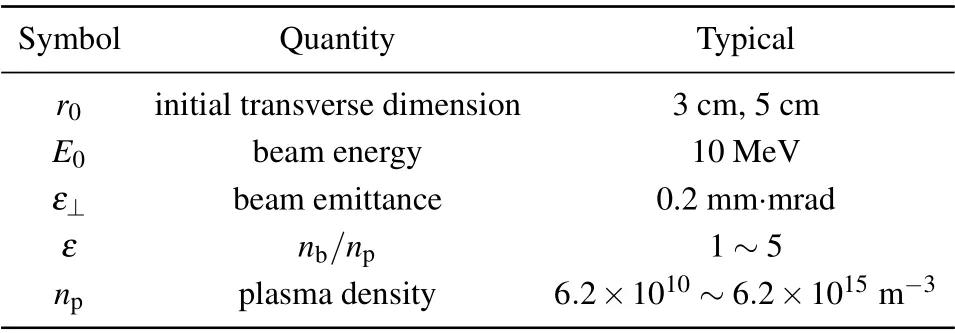
Table 1. Physical parameters of the beam and plasma.
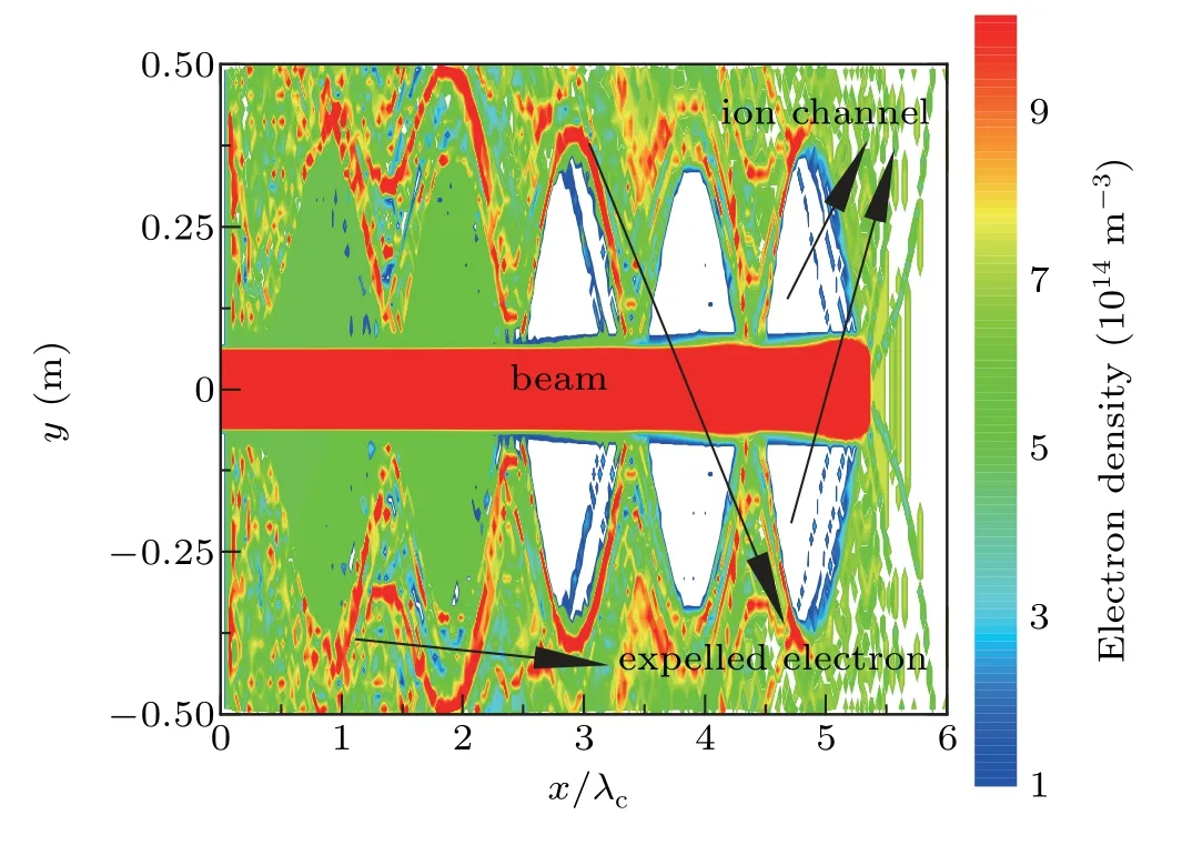
Fig.1. Schematic diagram of the ion channel oscillation.
2.2. Analytical model
2.2.1. Equilibrium transverse dimension of the ion channel oscillation
For ease of comparison with PIC simulations,the analytical model of the ion channel oscillation was built based on the propagation of a uniform sheet beam in the plasma. Figure 2 shows the profile of the ion channel, where the beam propagates along thexaxis while theyaxis points along the transverse direction,rcandhrepresent the equilibrium transverse dimension and amplitude of the ion channel oscillation,respectively.
Oscillation properties of the ion channel are determined by the force and motion of plasma electrons on the ion channel envelope. After being injected into the plasma environment,dynamics of the beam vary in a complicated manner. Consulting the relevant documentation,only the affection of the REB and plasma are firstly considered to calculate the equilibrium transverse dimensionrc. For a sheet beam with an infinite axial length,the transverse electric fieldEyis

whereepresents the fundamental charge. Wheny=rc,which means the electrons are in equilibrium, the transverse electric field should be zero. After substitutingy=rc,Ey=0 to Eq.(1),we obtain the calculation formula for the equilibrium transverse dimension
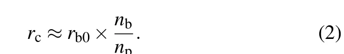
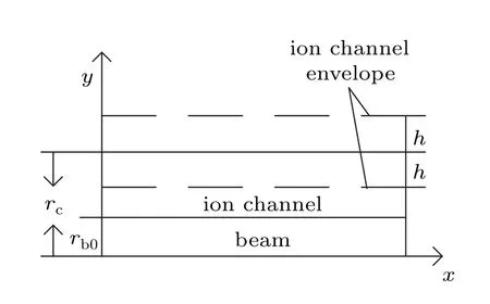
Fig.2. Profile of the ion channel.
2.2.2. The equations of motion of ion channel oscillation
In order to study the motion of plasma electrons on the ion channel envelope, it is necessary to take the influence of the REB,the ion channel,and Langmuir oscillation into consideration. According to the assumption that the axial length of the sheet beam is infinite,transverse electric fieldEybgenerated by the beam on the ion channel envelope can be obtained as

whereε0is the permittivity of vacuum. Therefore,the plasma electrons are expelled by the beam and a positive ion channel is formed. Owing to the fact that the positive ions are much heavier than electrons, the background plasma ions are considered to be static during propagation in this paper. A part of expelled plasma electrons distributes around the ion channel envelope and will oscillate resonantly with the ion channel.We named these electrons the“expelled electrons”which have been marked in Fig.1. Both of the positive ions in the channel and“expelled electrons”together form a structure similar to a parallel-plate capacitor. Then,the approximate transverse electric fieldEypbecomes
When the plasma undergoes a certain range of perturbations,the plasma electrons will be drove to neutralize the uneven distribution of plasma. Then, Langmuir oscillation will be formed. Under this condition,the transverse electric fieldEylis
According to Eq. (6), it is clear that plasma electrons on the ion channel envelope move around the equilibrium position repeatedly along the transverse direction. The ion channel oscillation which is formed by this motion is approximately the same as Langmuir oscillation.
3. Oscillation characteristics of the ion channel
3.1. Establishment of the ion channel
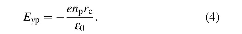
It is commonly accepted that a beam with a higher density than plasma could expel all the plasma electrons out of the beam and form a“pure”ion channel. After the REB has propagated for 16 ns, distributions of the ion channel generated by beams with various parameters have been shown in Fig.3.xis the propagation direction of the REB,yis the transverse direction of the REB, andλc=2πc/ωpis the wavelength of the ion channel oscillation. It is evident that the oscillation of the ion channel exists over the beam path. Whenε=1,the existence of blue parts in the ion channel means that the beam cannot expel all the plasma electrons out of the channel.Parts of plasma electrons are able to enter the channel with the oscillation and the channel can even close completely in certain locations,which indicates that the ion channel is relatively unstable. In Fig. 3(c), asεincreases, although the ion channel which is established latest in the beam head remains closing completely,fewer residual plasma electrons appear in the channel over time(x/λcdecreases),which indicates that a stable ion channel has been established asεincreases.
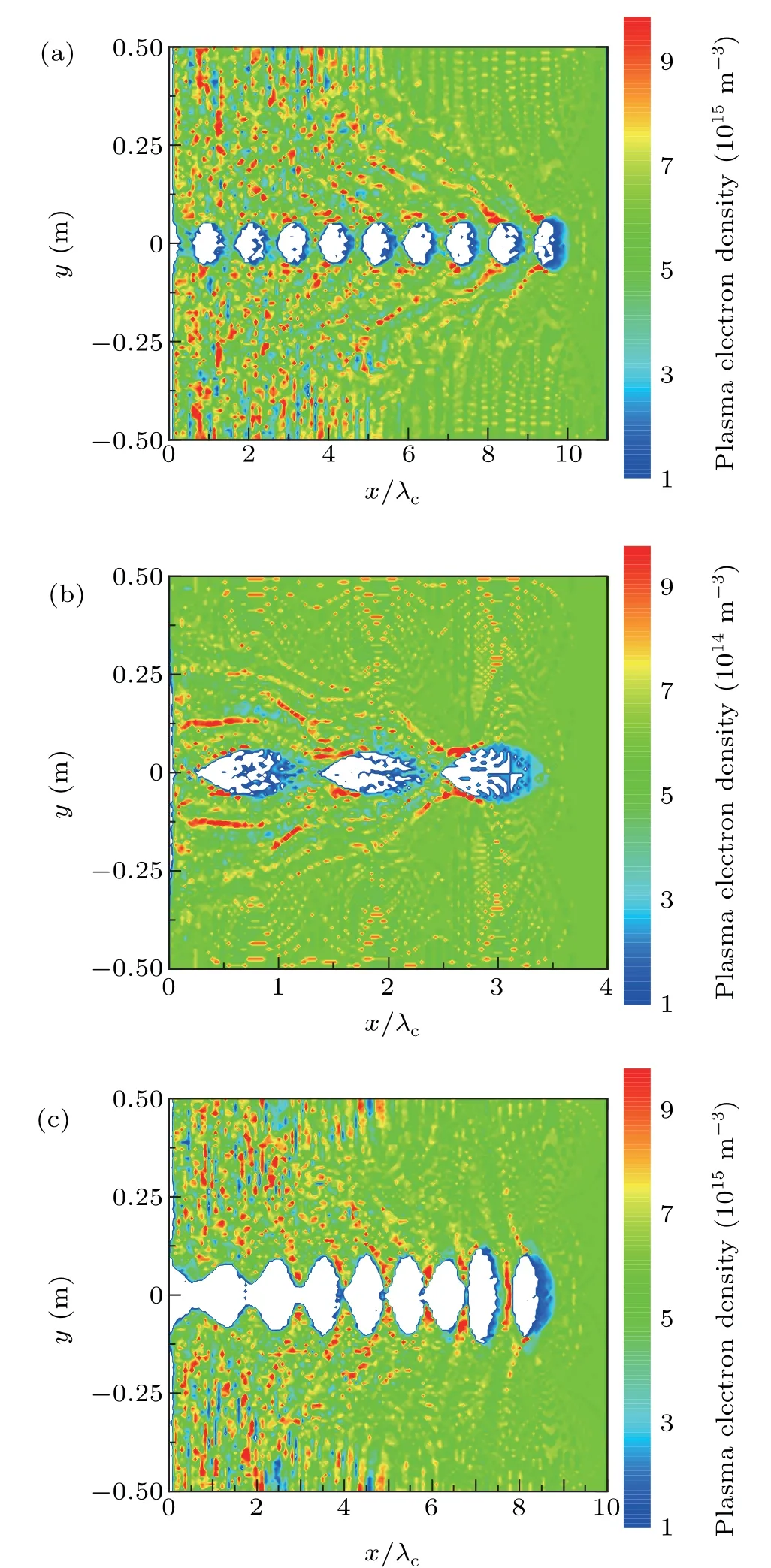
Fig.3. Distributions of the ion channel when the beam density is close to the plasma density: (a) np =6.2×10¹⁵ m−3, ε =1; (b) np =6.2×10¹⁴ m−3,ε =1;(c)np=6.2×10¹⁵ m−3,ε =2.
“Expelled electrons” can also affect the stability of the ion channel. During the process that the plasma electrons are expelled out of the channel, transverse kinetic energy of electrons is associated with their initial distributions. Plasma electrons which locate near the beam at the beginning possess higher transverse kinetic energy. Once the oscillation of the ion channel begins, these electrons, which have been named by“expelled electrons”,distribute out of the ion channel envelope and oscillate together with the channel at a larger amplitude.When the“expelled electrons”have accumulated enough transverse kinetic energy,they will run away from the channel and continue the transverse motion. This process has been shown in the red and yellow parts in Fig. 3. Also, as more“expelled electrons” distribute out of the channel in the first oscillation period,influence of“expelled electrons”on the ion channel is larger in the head of the beam. During the oscillation process,the influence of“expelled electrons”decreases as part of these electrons escape from the ion channel gradually.It can be concluded that whenε ≥1, the ion channel is able to be established,while the channel may be unstable. Interactions between the REB and plasma,oscillation of plasma,and other multiple physical processes commonly affect the quality of the channel and,subsequently,affect the long-range propagation of the REB in the plasma environment.
3.2. Effect of the beam density
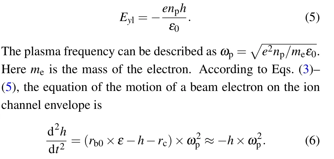
Fig. 4. Distribution of the ion channel when ε = 3, rb0 = 3 cm, np =6.2×10¹⁴ m−3. (a)PIC simulation,(b)comparation between the PIC simulation and the analytical model.
The oscillation of ion channel may disturb the propagation of the REB. It is necessary to choose appropriate beam parameters based on the various plasma environments for the improvement of the stability of the ion channel. Distributions of the ion channel whenε=3 and 5 are shown in Fig.4 and Fig. 5, respectively. The results were verified by comparing the PIC results with the results obtained by the analytical model. Taking into consideration that the approximation about“expelled electrons”in analytical model is more similar to the first period of the ion channel oscillation, the data of PIC simulations are derived from the ion channel in the head of the beam. The PIC simulation results are in good agreement with the analytical model results, shown in Figs. 4(b)and 5(b). By comparing Figs.4(a)and 5(a),it is obvious that as the beam density increases, the transverse force which the beam applies on the plasma electrons increases. There are few residual electrons left in the ion channel and the channel rarely closes completely. All these phenomena indicate that the ion channel becomes more stable. Additionally, the equilibrium transverse dimension (rc) positively correlates with the beam density (nb) according to Eq. (2). The plasma electrons possess more transverse kinetic energy when they arrive at the equilibrium position as the equilibrium transverse dimension increases. This is the reason for the increase of the amplitude in Fig. 5(b). Combining the results shown in Figs. 4 and 5,it can be concluded that increasing the beam density to a certain extent contributes to the establishment of a more stable ion channel.
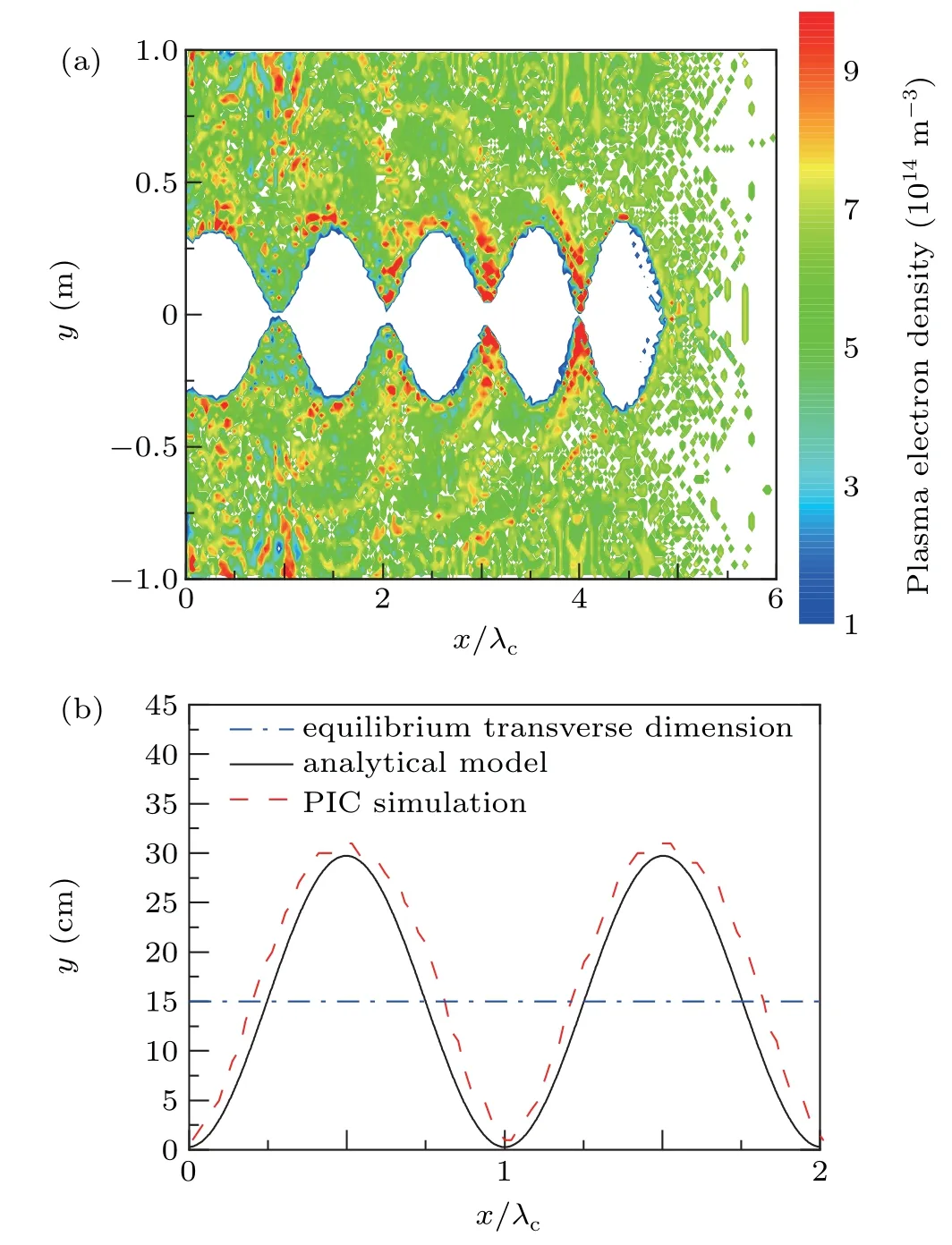
Fig. 5. Distribution of the ion channel when ε = 5, rb0 = 3 cm, np =6.2×10¹⁴ m−3. (a)PIC simulation,(b)comparation between the PIC simulation and the analytical model.
3.3. Effect of the initial transverse dimension of the REB
It is observed in Eq.(2)that the relationship between the initial transverse dimension of the REB and the equilibrium transverse dimension of the ion channel is proportional. The distribution of the ion channel whenrb0is increased from 3 cm to 5 cm compared with Fig. 4 is shown in Fig. 6. Increasing the beam density and initial transverse dimension of the REB have the similar influence on ion channel in analytical model.However, the more detailed physical properties in these two conditions are nuanced, shown in PIC simulation results. By comparing Figs. 5(a) and 6(a), it can be concluded that under the premise of the equal equilibrium transverse dimension,more residual electrons are left in the ion channel whenrb0increases. This phenomenon can be explained as follows: when the plasma electrons oscillate to the trough,which also means|y|reaches its minimum,more plasma electrons are able to enter the ion channel because of the largerrb0. Influence of these electrons on the quality of ion channel is not considered in the analytical model, resulting in the difference between the two approaches.
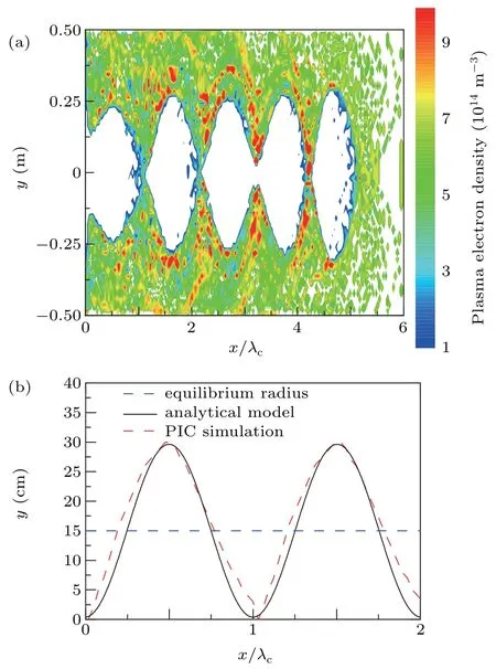
Fig. 6. Distribution of the ion channel when ε = 3, rb0 = 5 cm, np =6.2×10¹⁴ m−3 (a)PIC simulation,(b)comparation between PIC simulation and analytical model.
3.4. Effect of the plasma density
In order to keep the equilibrium transverse dimension consistent with Fig. 4, the plasma density and the beam density are increased ten-fold simultaneously and the distribution of the ion channel in this condition is shown in Fig. 7. The plasma frequencyωpincreases while increasingnp. In accordance with Eq. (6) in Subsubsection 2.2.2, it is evident that the transverse acceleration will be improved in this condition,resulting in the increase of frequency and the decrease of the amplitude of the ion channel oscillation. Also,this variation is shown in the PIC simulations in Fig.7(a). Additionally,as the amplitude decreases,distance between the trough of the oscillation and thexaxis becomes greater. Almost all the residual electrons are expelled, causing the distribution of more“expelled electrons”out of the ion channel envelope. As discussed in Subsection 3.1, the first period of the oscillation is most affected by“expelled electrons”. Thus,a special feature of oscillation appears in part of the ion channel which locates at the head of the beam,shown in Fig.7(a).
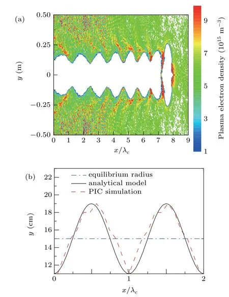
Fig. 7. Distribution of the ion channel when ε = 5, rb0 = 3 cm, np =6.2×10¹⁵ m−3. (a)PIC simulation,(b)comparation between the PIC simulation and the analytical model.
4. Long-range propagation of REB in the ion channel
4.1. Effect of the ion channel on the axial velocity of REB
At the altitude of 300 km,the ambient space plasma density is approximately 6.2×10¹²m−3in the atmosphere.[7]Figure 8 shows the distributions of REBs with same parameters after long-range propagation in plasma environment and in vacuum,while different colors indicate either the transverse velocity of plasma electrons or the axial velocity of the beam.Comparation of axial velocities of the beams between these two conditions is shown in Fig.9. In Fig.8(a),under the influence of space–charge effects,beam electrons in the beam head are accelerated by other beam electrons,while beam electrons in the beam tail are deaccelerated. In the beam tail,kinetic energy of beam electrons is converted into potential energy under the influence of axial electric field. In this situation,the beam is more easily to expand transversely. The envelope equations in the paraxial axial approximation can be used to explain this phenomenon. In envelope equations, variation of the beam envelope caused by the energy loss and self-field of the sheet beam can be written as[31]
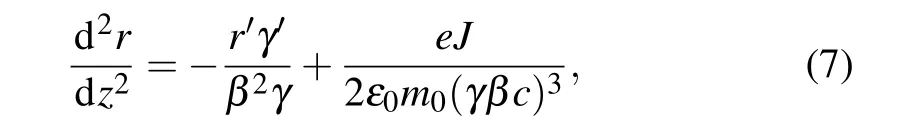
whereJandrrepresent current density and transverse beam envelope,respectively;m0represents the rest mass of the electron;ε0denotes the vacuum permittivity;c=2.998×10⁸m/s is the speed of light in vacuum.γ′is negative because of the continual decrease of beam velocity during propagation,which means both energy loss and the self-field of the beam will lead to a transverse expansion. When the axial velocity of the REB decreases,γreduces accordingly. Based on Eq. (7), beam envelope is more likely to be affected by the energy loss and the self-field asγdecreases. Thus,decrease of the axial velocity will cause an obvious transverse expansion and finally lead to a low transport efficiency of REB. When an REB with same parameters propagates in space plasma environment,it is clear that the space–charge effect of the beam is effectively suppressed by the positive ion channel,as shown in Figs. 8(b) and 9. The axial velocity is close to the initial velocity of REB during propagation and there is no transverse expansion in the beam tail. However, the ion channel oscillates consistently during propagation. When the plasma electrons oscillate to the trough (minimum of|y|), parts of these electrons are able to move into the beam and counteract the focusing effect of ions,leading to the oscillation of beam axial velocity with similar frequency to the ion channel.
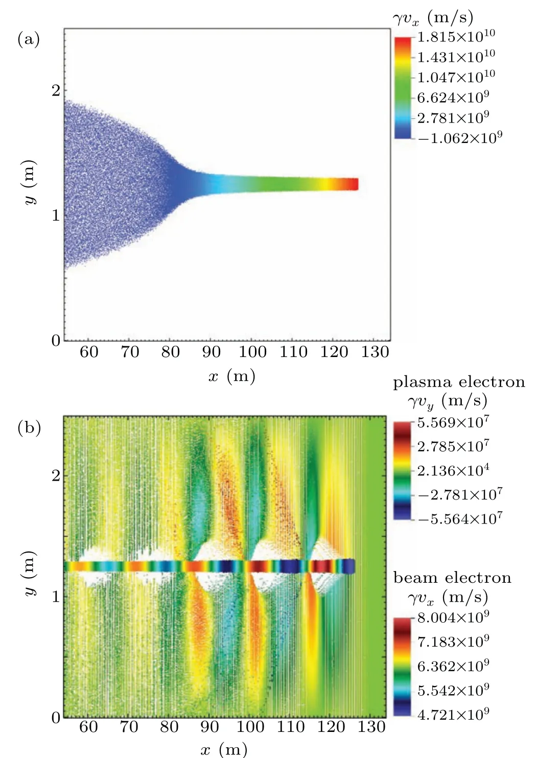
Fig. 8. Distributions of REBs after long-range propagation: (a) in the vacuum,(b)in the ion channel,ε =3,rb0=3 cm,np=6.2×10¹² m−3.
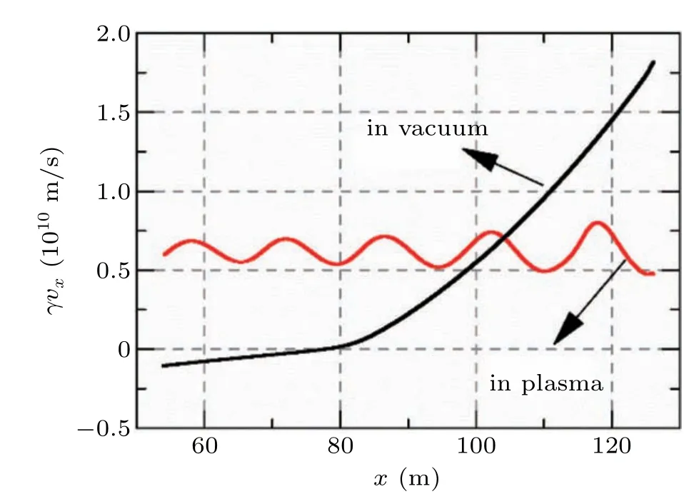
Fig.9. Comparation of axial velocity of the beam in vacuum and in plasma environment.
4.2. Instability of REB during long-range propagation in space plasma environment
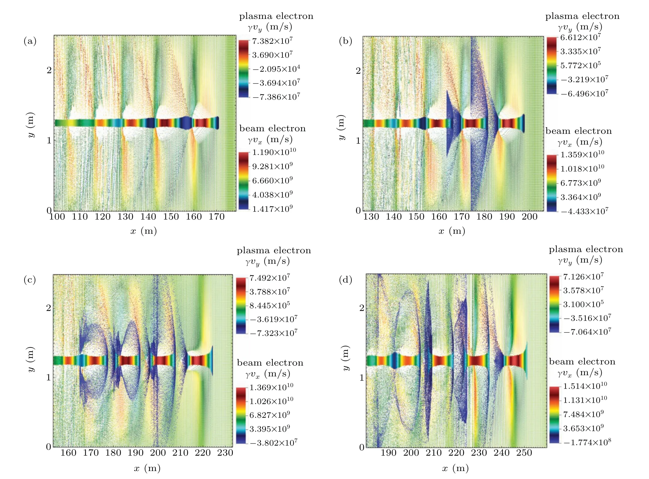
Fig.10. Instability of REB in the ion channel when ε=5,rb0=3 cm,np=6.2×10¹⁵ m−3,ε⊥=0.2 mm·mrad:(a)x=170 m,(b)x=200 m,(c)x=225 m,and(d)x=250 m.
Combining the results in Section 3 and Subsection 4.1,increasing the density or the initial transverse dimension of the REB according to the plasma environment can be an effective method to improve the quality of the ion channel. Increase of these two parameters leads to a larger beam current,which is also necessary for practical applications. However,according to the results in the previous section, there is a synchronous oscillation of axial velocity of the beam with the ion channel. As the propagation distance increases, this oscillation will eventually develop into the instability of REB, which is closely related to the beam current. Distributions of the REB and the time when the instability occurs are shown in Figs.10 and 11,respectively.tmaxis the time when the instability occurs in the plasma with a density of 6.2×10¹⁰m−3and it is used to normalize the characteristic time of the beam instability in this paper. The two-stream instability usually occurs when two collections of charged particles interact in velocity space in such a way that a density perturbation in one population instigates a response in the second population which causes the original perturbation to grow.[7]During the long-range propagation of the REB in the plasma environment,because of the oscillation of the axial velocity of the beam,bunching effect occurs between beam electrons. Ion channel oscillation may also lead to the bunching effect between beam electrons and plasma electrons. As a microscopic instability,two-stream instability can induce other macroscopic instabilities,such as resistive hose instability.[32]Thus,a serious instability phenomenon appears,as shown in Fig.10. Due to this,the energy of the REB is changed to plasma electrons and the efficient beam transport is disrupted. As the plasma density increases, frequency of ion channel oscillation as well as the oscillation of the beam axial velocity improves. Instability of the beam appears earlier,as shown in Fig.10.
If the small amplitude disturbances are limited with frequency near the plasma frequency,the e-folding time of twostream instability can be represented by the characteristic growth period[33]
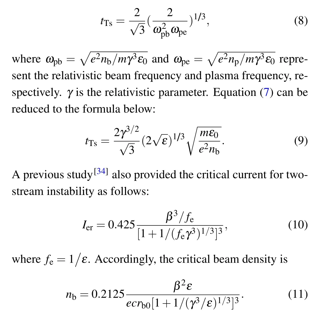
The critical beam density for the REB in Fig.10 is 5.8342×10¹⁴m−3, which means the two-stream instability could be possible in this condition. Combining Eqs.(8)and(9),it can be concluded that a rising beam current may lead to an earlier occurrence of two-stream instability while all the other parameters are held constant. The conclusion is consistent with the results in Fig. 11. Besides, compared to Fig. 10, figure 12 illustrates the distribution of REB with a ten-fold emittance.When the beams have propagated the same distance,the twostream instability occurs for the beam with a smaller emittance in Fig.10,while the beam with a larger emittance is more stable. This is mainly because the transverse spread caused by the beam emittance suppress the occurrence of the instability.Also, increase of the beam emittance leads to a decrease in the beam density. This may result in a later occurrence of instability according to Eq. (8). REB in Fig. 12 can propagate to a larger distance stably. It can be concluded that the twostream instability may become a main limitation to the longrange propagation of an REB in the plasma environment and it should be considered when choosing the parameters of the REB.

Fig. 11. Normalized time when the instability appears in the plasma with different plasma densities.
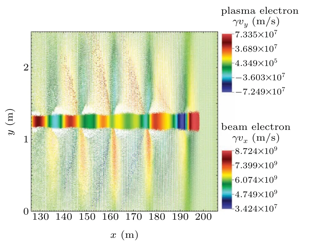
Fig.12. Distributions of REB with a ten-fold emittance ε⊥=2 mm·mrad.
5. Conclusion
After being injected into the space plasma environment,the REB can expel the plasma electrons radically and form a positive ion channel. Properties of the ion channel is important to investigate the long-range propagation of the REB.This article aimed to study the physical properties of REBs during long-range propagation in space plasma environment by using PIC-MCC simulation. The numerical results could be concluded as follows.
The ion channel continues to oscillate during propagation of the REB owing to the influence of beam and plasma. The characteristics of ion channel show a close relationship with the beam and ambient plasma parameters, such as the beam density,the initial transverse dimension of the REB and ambient plasma density.
During the long-range propagation of the REB in vacuum,beam electrons in the beam tail are deaccelerated because of the space-charge effects. Decrease of the axial velocity will cause an obvious transverse expansion and finally lead to a low transport efficiency. When the REB propagates in space plasma environment, the space-charge effects of the beam is effectively suppressed by the positive ion channel. However,as the ion channel oscillates consistently during propagation,beam axial velocity also oscillates with a similar frequency to the ion channel.
As the beam have propagated in the ion channel for a period of time, an instability occurs and disrupts the stable propagation of the REB.The oscillation of beam axial velocity may lead to the two-stream instability and further other macroscopic instabilities. The time this instability occurs shows a close relationship with the beam density.
According to the results in this paper,it can be concluded that an appropriate choice of beam parameters will contribute to the establishment of ion channel and improve the REB transport efficiency during long-range propagation in space plasma environment. The results of this study may inspire further study of REBs and the application of ion channel in the active space-based experiments.
猜你喜欢
杂志排行

Chinese Physics B的其它文章
- Heterogeneous traffic flow modeling with drivers’timid and aggressive characteristics∗
- Optimized monogamy and polygamy inequalities for multipartite qubit entanglement∗
- CO2 emission control in new CM car-following model with feedback control of the optimal estimation of velocity difference under V2X environment∗
- Non-peripherally octaalkyl-substituted nickel phthalocyanines used as non-dopant hole transport materials in perovskite solar cells∗
- Dual mechanisms of Bcl-2 regulation in IP3-receptor-mediated Ca2+release: A computational study∗
- Diffusion of nucleotide excision repair protein XPA along DNA by coarse-grained molecular simulations∗