Numerical Simulation of Semisubmersible Accommodation Platform Going Alongside FPSO Under the Control of Dynamic Positioning System
2022-06-18-,-,-,-,-
-,-,-,-,-
(1.College of Automation,Harbin Engineering University,Harbin 150001,China;2.China Ship Scientific Research Center,Wuxi 214082,China)
Abstract:A semisubmersible accommodation platform is usually equipped with a DP system.With the aid of the DP system,the platform can hold its position and go alongside offshore production platforms.Because of the complicated ocean environment, it is dangerous for the semisubmersible accommoda⁃tion platform performing berthing operation while the target platform is moving.To estimate the risk of this process,the numerical models of semisubmersible accommodation platform,FPSO and ocean envi⁃ronment were built.Also,DP control algorithm for ensuring the semisubmersible accommodation plat⁃form to go alongside the target platform within a safe berthing speed range was designed. The simula⁃tion results show that it is feasible for the semisubmersible accommodation platform to go alongside the FPSO under some rough sea states and the speed of the platform can be effectively controlled.
Key words:semisubmersible accommodation platform;DP system;numerical simulation;berthing
0 Introduction
A semisubmersible accommodation platform, as shown in Fig.1, is mainly used to transfer re⁃plenishment and crew on the sea. Its specific functions include providing a comfortable environment,living facil⁃ities and medical services for hundreds of offshore work⁃ers[1]. It is also used to carry out material supply, storage and transshipment for offshore production platforms. In order to perform replenishment operations, the semisub⁃mersible accommodation platform needs to go alongside an offshore production platform under the control of DP system and the gangway is used to connect a production platform.During the idle period,the semisubmersible ac⁃commodation platform adopts a mooring system to stand by in the distance from the production platform.

Fig.1 Semisubmersible accommodation platform
The replenishment operations of a semisubmersible accommodation platform in waves are com⁃plex. One thing to note is that the motion of platform is affected by the environmental loads such as waves,wind and current.At some certain wave frequencies,the motions of floating body can be am⁃plified by superimposed waves[2],and water resonance has been observed in the narrow gap between floating bodies[3-4]. Another thing to note is that the horizontal motions of platform which is going to be replenished are constrained by nonlinear mechanical connections such as moorings,fenders,and hawsers[5]. These constraints limit the amplitude of the motions while reducing the maneuverability of platform in emergency circumstances. For these reasons, it is critical to maintain a safe relative distance between accommodation platform and production platform when the replenishment opera⁃tions are performed. For the sake of safety, a semisubmersible accommodation platform is usually equipped with four to six azimuth thrusters and has DP2 or DP3 level dynamic positioning capabili⁃ty to ensure that it can hold position or follow the movement of the production platform to keep a rel⁃ative distance accurately. The motion control strategy is the key technology for maintaining the berthing velocity and relative position between the platforms simultaneously. Studies on dynamic positioning of floating body have usually focused on fixed-point control problems[6-8]while there are few studies reporting the investigation of the controller design about replenishment operations of semisubmersible accommodation platforms. The similar studies such as ship-to-ship transfer of LNG[9-10], underway replenishment operations between two sailing ships[11-13], and pipelaying opera⁃tions[14]concern more about the distance between two vessels rather than the relative velocity, but the control strategies in those studies can be used for reference.
In this study, a DP controller is designed to control the relative velocity and position between the semisubmersible accommodation platform and FPSO. The process of the platform going along⁃side FPSO is simulated in the time domain, and the motions of platform and thruster power con⁃sumption results are analyzed after the simulation.
1 Time domain numerical model of platform
1.1 Coordinate system
A right-handed cartesian coordinate system is used in this study.As shown in Fig.2,the earthfixed reference frame is denoted as theO0-X0Y0Z0-frame and its originO0is located at the water sur⁃face.The body-fixed frame denoted as theG-XYZ-frame is fixed to vessel body and its originGis located at the center of grav⁃ity. TheGXaxis lies in the mid-longitudi⁃nal plane and it is parallel to the water plane while theGZaxis is perpendicular to the water plane and is positive when pointing upwards. TheOYaxis is positive when pointing to the port side[15].
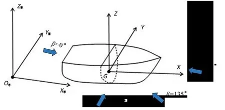
Fig.2 Coordinate systems of platform
The direction angle of the environmental load is the angle between the environmental load vec⁃tor and theO0X0axis. Whenβis equal to 0°, 90° and 180°, it is defined as following sea (down⁃wind),beam sea(cross wind),and head sea(head wind)respectively.
1.2 Motion equations
According to Cummins[16]and Fossen[17], the 6-DOF motion equations of the semisubmersible accommodation platform and offshore production platform defined in respect to the coordinate sys⁃temO0-X0Y0Z0can be expressed as

whereρwis the density of seawater,Cdfis the current drag coefficient matrix,Tis the draft of plat⁃form,UFlowis the velocity vector of current.
1.3 Model of mooring lines
The lumped-mass method was used to simulate the mooring lines of the offshore production platform. As shown in Fig.3, the lumped-mass method is a simplified model in which the distribut⁃ed mass of the mooring line has been replaced by a series of discrete masses attached to a weight⁃less,extensible spring.
According to the lumped-mass method, the motion equation of the mooring line can be ex⁃pressed as Eq.(6), whereMnodeis the mass matrix of node;Anodeis the added mass matrix of node;ηnodeis the position vector of node;Tupis the force vector of topside spring to the node;Tdownis the force vector of downside spring to the node;FDis the fluid drag force vector to the node, which can be obtained by Morrison formula;Gis the gravity vector of node.
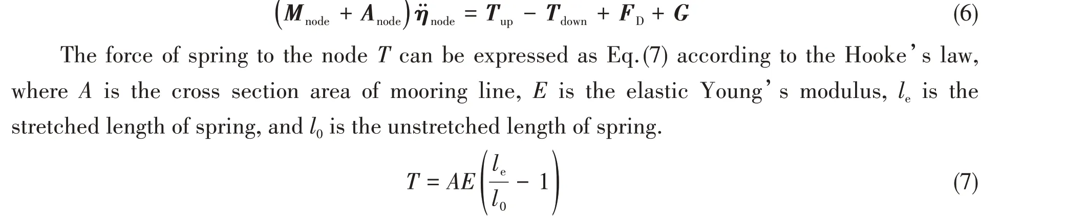
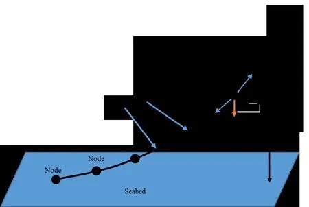
Fig.3 Discrete representation of mooring line
1.4 Low frequency motion estimation method of DP system

wheresis the complex parameter,aandbis the filter coefficients,andnis the order of filter and it is equal to 2 in this study.
1.5 Control algorithm of DP system
The control algorithm is the core part of the DP control system, and its role is to calculate the necessary thrust to ensure that the marine structure moves according to the expected trajectory. In this study, the PID controller is used to control the three degrees of freedom on the horizontal sur⁃face of the marine structure,namely,surge,sway and yaw.
The basic formula of the PID controller can be expressed as[21-22]:

whereKpis the proportional coefficient matrix,KIis the integral coefficient matrix,KDis the differ⁃ential coefficient,ande( )
tis the error vector.The berthing speed of the semisubmersible accommodation platform should be controlled when moving to the production platform from a distance and it is important to ensure that the berthing speed of the platform can be maintained within a safe speed range because it is too difficult to stop the platform while it is moving too fast. Therefore, the control system needs to control the position and speed of the marine structure at the same time. In order to control the speed of the platform, a revised PID controller is used in this study,and the basic formula of the controller can be written as:

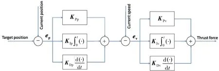
Fig.4 Control algorithm structure
1.6 Target position calculation method
The accommodation platform should keep on tracking the trajectory of the production platform so that the target position for the accommodation platform is changing all the time. For the accom⁃modation platform, it can be obtained by calculating Eq.(11) to obtain the target position, whereTpsis the target position vector of accommodation platform;Ris the rotation matrix,which is expressed as Eq.(12);ψis the heading of tracked object;Dis the position vector which represents the distance between target position and CG position of the tracked object in the body-fixed frame. Considering the length of the gangway which is about 35±7.5 m,Dcan be expressed as Eq.(13),whereLGis the length of gangway,BFis the breadth of FPSO,BPis the breadth of accommodation platform,andXis the position vector of CG position of the tracked object in earth-fixed reference frame.

2 Numerical calculation and result analysis
2.1 Object of study
In this study the semisubmersible accommodation platform with 4 azimuth thrusters is taken as the study object. The principal dimensions of the platform are shown in Tab.1, and its thruster lay⁃out and maximum thrust are shown in Tab.2.

Tab.1 Principal dimensions of the semisubmersible accommodation platform
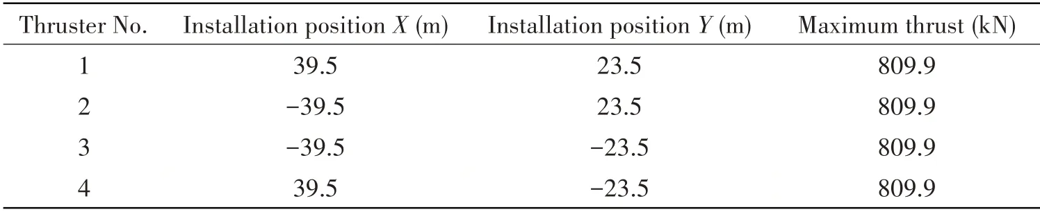
Tab.2 Thruster layout and maximum thrust
2.2 Tracked object
The tracked object of the semisubmersible accommodation platform is a single-point moored FPSO.Its principal dimensions are shown in Tab.3.

Tab.3 Principal dimensions of the FPSO
The properties of the mooring system of FPSO are shown in Tab.4.The number of moor⁃ing lines is 12, and these mooring lines are di⁃
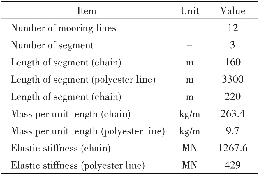
Tab.4 Properties of the mooring system used in numerical system
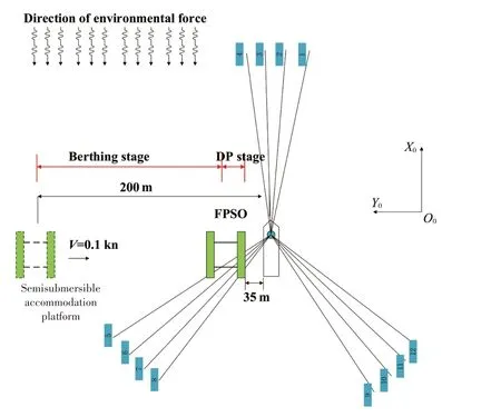
Fig.5 Schematic diagram of berthing process and layout of mooring system
vided into three groups. Each group is separated by 120° and the lines in the same group are sepa⁃rated by 5°.The layout is shown in Fig.5.
2.3 Descriptions of berthing process
The process of the semisubmersible accommodation platform going alongside FPSO is shown in Fig.5,and it is simulated in this study.The platform starts sailing under the control of DP system at a distance of about 200 m from the FPSO.During this time,which can be called berthing stage,the platform will maintain a certain safe speed (it is about 0.1 kn≈0.0514 m/s, which refers to the DP operator’s experience) to reach the target position while the target position is changed with the mo⁃tion of FPSO in real time. When the platform reaches about 35 m from the one side of FPSO, the speed of the platform is reduced to 0 kn at this time (DP stage) and the platform is going to hold its position.During DP stage,the gangway is going to be prepared for crew transportation.The platform should keep the same heading with FPSO so that secure connection between gangway and FPSO will be ensured.It should be noted that when the platform is sailing,the deviation between the actu⁃al speed and the target speed should not be too large for reducing the probability of collision be⁃tween FPSO and platform. Because there is a limit to length of the gangway (in this study the limit is 35±7.5 m), when the platform is at DP stage, the deviation between the position of the platform and the target position should not be too large either.
2.4 Environmental conditions
The environmental conditions are shown in Tab.5,which are typical sea states in the Brazilian waters.

Tab.5 Environmental conditions
2.5 Result analysis
(1)Results of Case No.1
As the results shown in Tab.6 and Fig.6, under the environmental conditions in which the sig⁃nificant wave height is 3.08 m, the wind speed is 13.11 m/s, and the flow velocity is 0.75 m/s, the maximum berthing speed of the platform during the berthing stage (before 2500 s) is 0.0532 m/s.The average berthing speed is 0.0512 m/s and its deviation from the target berthing speed 0.0514 m/s is small.When the platform reaches 35 m on the FPSO side,it enters the dynamic positioning stage(after 2500 s). At this time, the maximum position tracking error of the platform is 2.5 m, the aver⁃age position tracking error is 0.57 m, and the standard deviation of the position tracking error is 0.48 m.
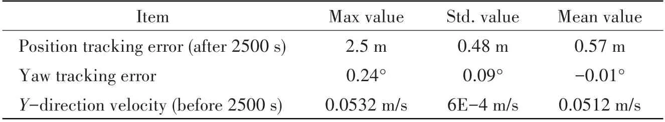
Tab.6 Statistical values of platform motion under Case No.1
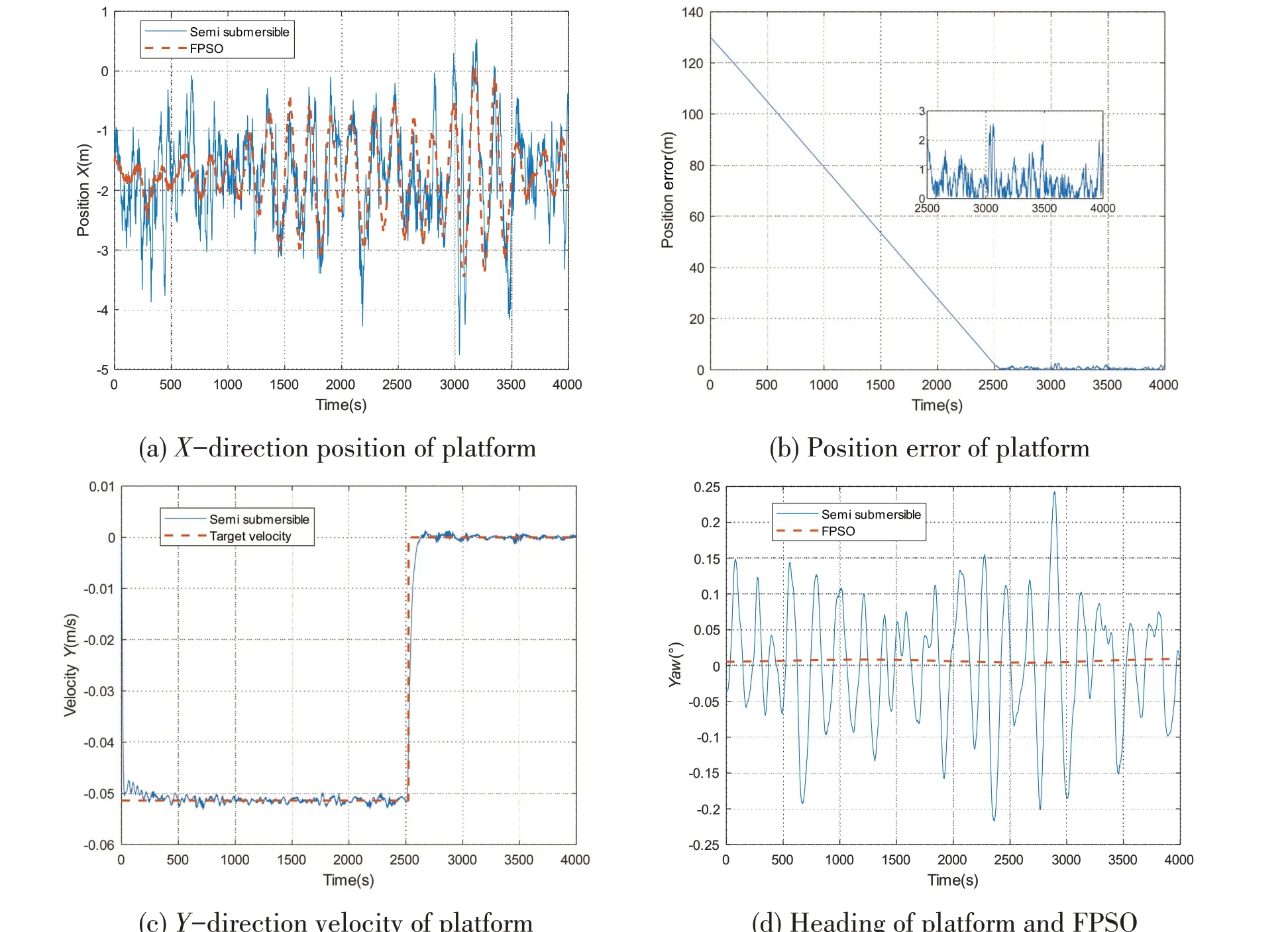
Fig.6 Simulation results of Case No.1
(2)Results of Case No.2
As the results shown in Tab.7 and Fig.7, under the environmental conditions in which the sig⁃nificant wave height is 4.2 m, the wind speed is 15.53 m/s, and the flow velocity is 0.75 m/s, the maximum berthing speed of the platform during the berthing stage (before 2500 s) is 0.0541 m/s and the average berthing speed is 0.0513 m/s.When the platform enters the DP stage(after 2500 s),the maximum position tracking error of the platform is 4.95 m,the average position tracking error is 0.75 m, and the standard deviation of the position tracking error is 0.69 m. It is obvious that the tracking error is greater than that of Case No.1.

Tab.7 Statistical values of platform motion under Case No.2

Fig.7 Simulation results of Case No.2
(3)Results of Case No.3
As the results shown in Tab.8 and Fig.8, under the environmental conditions in which the sig⁃nificant wave height is 6.8 m,the wind speed is 20.4 m/s,and the flow velocity is 1.14 m/s,the max⁃imum berthing speed of the platform during the berthing stage (before 2500 s) is 0.0589 m/s. The average berthing speed is 0.0511 m/s and it is close to the target berthing speed of 0.0514 m/s.When the platform enters the DP stage (after 2500 s), the maximum position tracking error of the platform is 8.41 m, which is beyond the permissible value (7.5 m) of the extended length of the gangway,therefor it is risky to perform gangway connection in this environment.

Fig.8 Simulation results of Case No.3
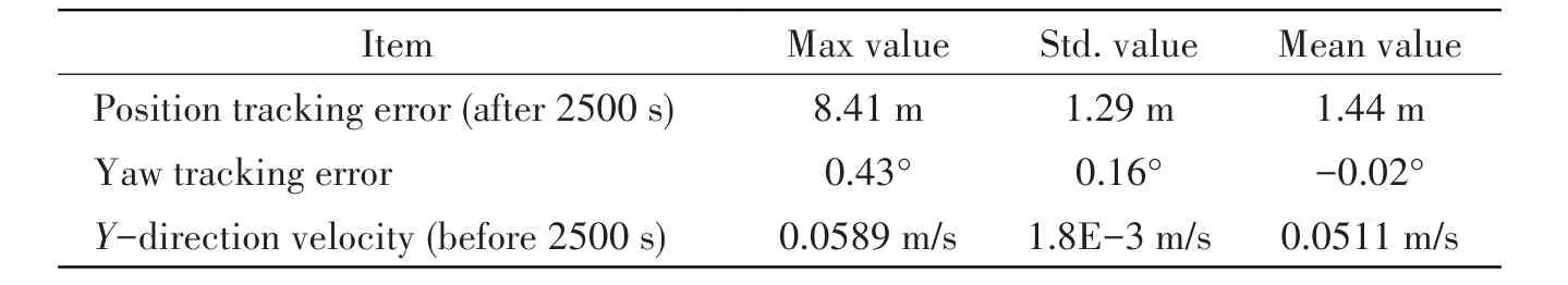
Tab.8 Statistical values of platform motion under Case No.3
(4)Results of power consumption
The results of power consumption are shown in Tab.9.Under Case No.1,the maximum thruster power is 63.43% of the total power, and the average thruster power is 17.39%. Under Case No.2,the maximum thruster power is 75.46%, and the average thruster power is 21.62%. Under Case No.3,the maximum power used by thruster is 98.77%,and the average value is 39.48%.It is known that for a dynamic positioning system, the maximum power of thrusters is generally limited to 80%of the total power, so the environmental conditions of Case No.3 are harsh for the platform to per⁃form the berthing operation.

Tab.9 Power consumption of semisubmersible accommodation platform
According to the results of platform motion and power consumption,it can be seen that the ac⁃commodation platform can keep its berthing velocity well under three different cases,while its posi⁃tion tracking and power consumption increase obviously as the significant wave height increases. It can be inferred that the control of berthing velocity is less affected by the environment disturbances than the control of position tracking in this study, and there is evident correlation between environ⁃ment disturbances,position tracking error and power consumption.
3 Conclusions
In this study,the process of a semisubmersible accommodation platform going alongside a sin⁃gle point moored FPSO under the control of a dynamic positioning system is simulated. The motion and thrust results under different operating conditions are obtained and the conclusions can be sum⁃marized as follows:
(1)The control structure of the dynamic positioning system designed in this study can effective⁃ly control the motion of the semisubmersible accommodation platform.
(2) Under the environmental conditions in which the significant wave heights are 3.08 m and 4.2 m,the semisubmersible accommodation platform has good heading and position tracking perfor⁃mance for FPSO, and the berthing velocity of the platform is maintained well. It is safe to go along⁃side FPSO under these conditions.
(3)Under the environmental condition in which the significant wave height is 6.8 m,the berth⁃ing velocity of the platform remains good, but the position tracking error for FPSO increases, and the maximum total power of the thruster reaches 98.77%.There is a risk to perform berthing opera⁃tion under this condition.
In this study,the operating condition in which the semisubmersible accommodation platform is covered by the production platform is not considered. The simulation and model experiment will be further carried out in future work.
杂志排行

船舶力学的其它文章
- Study on the Loads of Connectors for a RMRC Hexagon Enclosed Platform Model in Waves
- Behavior of Crude Oil Leakage from Underwater Damaged Hole of Oil Tank in Waves
- Dynamic Response of Shipbuilding Sandwich Plates with Functionally Graded Soft Core Subjected to Impulse Loading
- Dynamic Response Analysis of a New Semi-submersible Offshore Wind Turbine Based on Aerodynamic-Hydrodynamic Coupling
- Investigations on the Quasi-static Stability Behavior of an Innovative Subsurface Tension Leg Platform in Ultra-Deep Water(Part II)
- Ship Local Path Planning Based on Improved Q-Learning