Power Control Based on State Space Strategies for Grid-Oriented Inverters with LCL Filters
2022-05-20ChunyuLuWeiHuaandMingjinHu
Chunyu Lu, Wei Hua and Mingjin Hu
(School of Electrical Engineering, Southeast University, Nanjing 211189, China)
Abstract: Through a third-order mathematical model of grid-oriented LCL-type converters, this paper analyzes the complicated dynamic characteristics and resonance problems which may influence the system stability. To realize active damping for LCL filters and improve dynamic performance of current regulators, a state space current PI controller is proposed whose parameters can be tuned based on the polynomial equations approach. An extended state observer is integrated with the regulation scheme, where additional sensors are not necessary in contrast with conventional active damping strategies. Synchronous reference frame PLL (SRF-PLL) equipped with filter technology is proposed for grid voltage disturbance suppression. This method is then applied to establish a double-closed-loop power regulator that demonstrates improved performance compared with other controllers. The simulation results are displayed to illustrate the efficiency of the regulation methods.
Keywords: LCL-type grid-oriented converters; state space current control; SRF-PLL; closed loop power control
0 Introduction
Nowdays, distributed power generation systems are developing rapidly with the ever-increasing demand on renewable energy[1]. Because of the remarkable fluctuation of renewable energy, such as wind power and hydropower, distributed power system may encounter the degradation of efficiency and controllability[2], and the high-order switching harmonics caused by PWM strategy applied in converters for power transmission may deteriorate the grid-side current[3-4].
To efficiently attenuate the current ripple resulted from the grid-side inverter, a filter is usually connected in series between the inverter and the grid. Different from the L-type filter with an equal inductance, the LCL-type filter can obtain better harmonic attenuation[5]. Due to its lower cost and smaller size, LCL filters can acquired more attention in current harmonic suppression[6-7], whereas a drawback related to LCL filters is the resonance issue. The converter-side damping strategies can alter the equivalent impedance to ensure the controllability of power systems, which consist of inherent-damping methods, passive damping methods and active damping methods. An appropriate design may offer inherent damping for LCL-type power systems, whereas this strategy requires extremely strict matching of system digital delay and sampling position[8-10]. The passive damping methods are convenient to employment and have acquired a wide application in industrial fields. This type of methods can achieve better harmonic attenuation even under complex grid voltage disturbance at the expense of power loss[11-12]. Compared with passive damping, active damping can be more flexible and have no additional power loss[13]. However, additional sensors for state feedback may complicate the control configuration and decrease reliability.
State space regulation is prominent enough in the LCL-type control which enables the arrangement of the dominant dynamics and resonant dynamics[14]. This can be designed by choosing pole locations, by dead-beat strategies as well as by calculating the optimal cost function or with Bessel functions. Based on the direct pole placement, the regulation parameters could be achieved as the analytical expression incorporating characteristics of LCL-type systems. Meanwhile, to eliminate additional measurements in contrast with conventional controllers, several state estimation strategies are developed.
Currently, many power control strategies based on synchronous transformation are widely applied in grid-tied converters[15], which require the amplitude and phase information of grid-side voltage acquired by the PLL. For three-phase systems, the most common method is the synchronous reference frame PLL (SRF-PLL). SRF-PLL is an ideal algorithm of high quality that can work in high bandwidth and obtain great phase-locked response[16]. With regard to the grid voltage disturbance, the injection harmonics fromqaxis may deteriorate the ability of PLL, even leading to the instability.
In Refs. [17-19], the decoupled double SRF-PLL (DDSRF-PLL) method is proposed to attenuate the harmonic components and accurately extract the positive sequence component of grid voltage. Eventually, the target of grid-side controller design is to ensure the smooth power transmission between converters and the grid. Aimed at improving dynamic performance of power reference tracking, an enhanced power regulator is developed for single phase power converters in Refs. [20-21]. In three phase power systems, the coupling betweendaxis components andqaxis components will affect the robustness of power controllers, a decoupling parallel control strategy is proposed in Ref. [22] to diminish the coupling power disturbance.
The current control performance has a great influence on the power control performance. Nevertheless, in the LCL-type grid-oriented inverter, the PI controller associated with current combined with active damping is not effective. Although the state space control methods work well, but additional capacitive voltage sensors and grid-side current sensors are required, increasing control costs and making the system structure more complex. The innovations in this article are as follows:
1)Combining the state space controller with the state space observer, the full-order closed-loop control of the state variables is realized when only the inverter side current sensors are applied. Meanwhile, the sampling noise attenuation isrealized through the reasonable observer pole locations, which improves the current closed-loop performance.
2)The corresponding control parameter design method is deduced, and the control parameter design expression is simplified compared with the expression of the previous papers.
This paper is organized as follows. Firstly, the system model of grid-tied converters with LCL filters is illustrated in Section 1. Then, Section 2 describes the design of current regulator. A state space regulator related to current control for three-phase distributed generation system is developed according to continuous switching-cycle-averaged model of converters, whose phase angle is captured by SRF-PLL with loop filter. Taking the three-order characteristics of LCL-type converters into consideration, this paper proposes an extended Luenberger state observer to implement the observation of capacitor voltage and grid-side current based on the measurement of converter-side current, which can diminish extra sensors and act as the low pass filters. Next, Section 3 presents the design of power controller. A stable closed loop control strategy of reactive and active power is developed according to instantaneous power calculation principles, whose references are given by tracking differentiator for reduction of impact on the grid. Finally, simulation results are displayed in Section 4 and Section 5 summarizes the conclusions of this paper.
1 System Model

The series inductorsL′and the parallel capacitorsCsatisfies the following assumptions.
1)The inductance of series inductors and the capacitance of parallel capacitors are equal, respectively;
2)No mutual inductance exists between the three-phase series inductors.
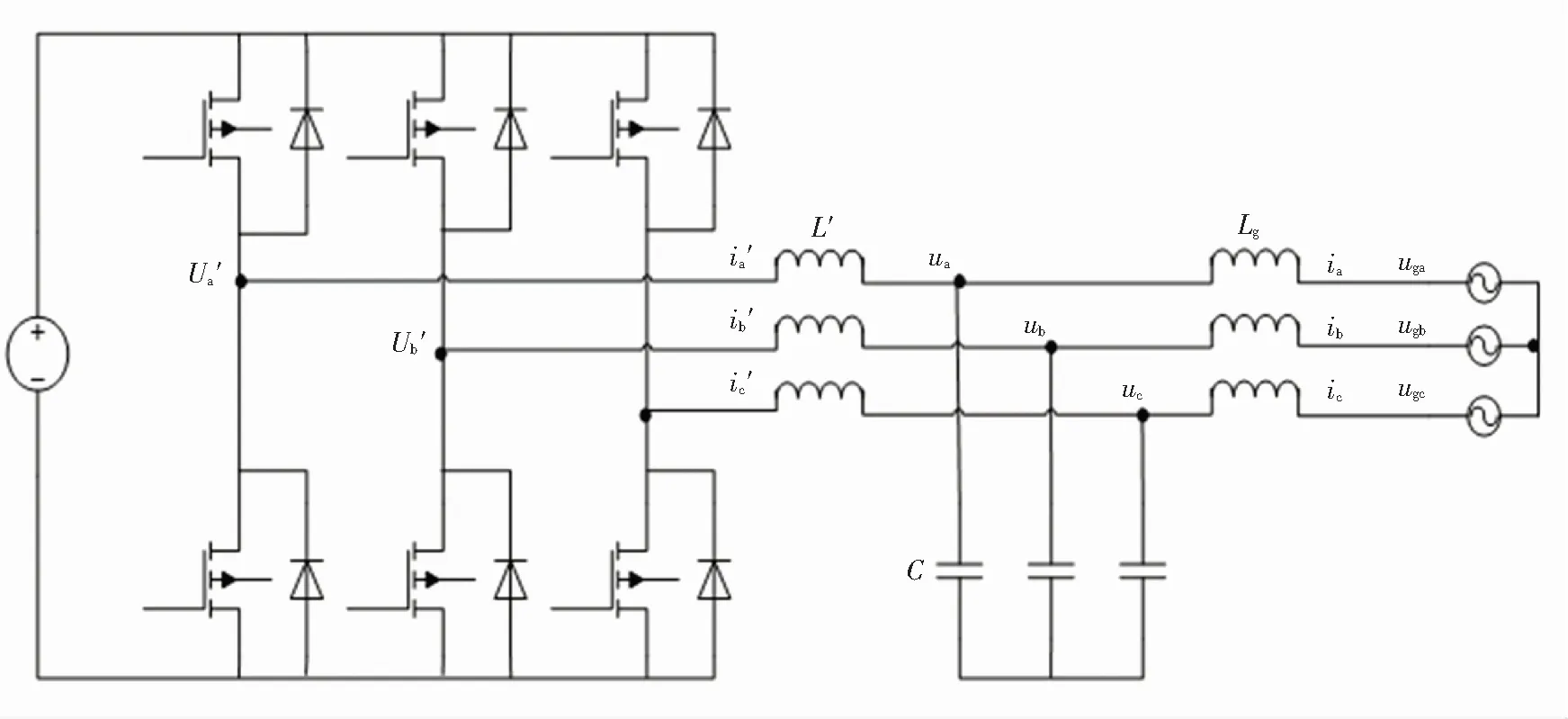
Fig.1 Configuration of grid side converters with LCL filters
1.1 State-Space Model for LCL Filter


(1)
As can be seen in Fig.1, the inverter-side inductance is defined asL′, the capacitance is defined asC.Besides,RsandLgare grid-side value of resistors and inductors respectively, whereωeis the grid angular frequency.
The transfer function from the converter voltage to the grid current can be calculated as follows:
(2)

(3)
1.2 Resonance Issues
The filter parameters are designed according to classical LCL filter design principles associated with current ripple and reactive power restriction. The simulation system specifications are given in Table 1. The Bode diagram of open loop functionGc(s) is displayed in Fig.2 where the resonant frequency is 4.6 kHz. Near the resonant frequency, the open-loop gain ofGc(s) is greater than 0, and the phase angle will convert from -90° to -270° which may be responsible for the instability of the converter systems.

Table 1 Simulation parameters

Fig.2 Bode diagram of open loop converter systems with LCL filters
2 Current Control Design

The feedback control on grid currents as well as on capacitor voltages and converter currents are implemented based on state space control strategies. In comparison with conventional PI control, control degrees of freedom (DOFs) are improved and better parameters can be obtained through flexible parameter design.

Fig.3 Diagram of state space PI control with extended Luenberger state observers
2.1 State-Space PI Controller
In order to simplify the analysis process, the influence of the grid angular frequencyωecoupling is temporarily ignored, then the dqaxis relationship between grid current and converter-side voltage can be analyzed independently. Based on theqaxis model, the design of state space PI controller is analyzed. The state space model ofqaxis is defined as

(4)
To suppress the steady-state error of current response, a state variable related to error integration is combined with previous model, which is defined as
(5)
According to the above definition, theqaxis current state space controller can be designed as follows:
igq=CgXq
(6)
wherektqandkiqare the tracking parameter and the integration parameter respectively whenk1q,k2q,k3qare defined as the state feedback gain.
Therefore, theqaxis current model equipped with state space strategies can be derived as

(7)
Then, the transfer function for grid current from converter-side voltage is expressed as
(8)
The dynamic characteristics of theqaxis current regulation are configured by the polynomial equations approach , and the pole selection can be performed by the following classic equation:
(9)
whereξ1is the passband damping ratio,ω1is the passband bandwidth,ξ2is the resonance damping ratio, andω2is the resonance frequency.
As shown in Eq.(9), the system can realize the decoupling of the passband characteristics and the attenuation characteristics of high frequency where the gains are selected properly. Meanwhile, the suppression of the high-frequency resonance and the selection of the resonance frequency can be implemented. Compared with the current loop controller design based on PI controller, the state space methods have higher efficiency and flexibility.
After equivalent calculation, the coefficients of the state space method can be determined as
k3q=2L′(ξ1ω1+ξ2ω2)-L′RsC
(10a)
(10b)
(10c)
(10d)
(10e)
In Eq.(10e),ais the zero location of the closed-loop system, which is usually selected near the cutoff frequency, which can be adjusted to enhance the dynamic performance of the system. Similarly, thedaxis current loop coefficients can be calculated.
2.2 State-Space Observer
Regardless of the state space controller or the PI controller combined with the active damping method, additional voltage sensors or current sensors are required to access the state feedbacks, which inevitably raise the design cost and complexity of the control structure, and reduce the feasibility. Hence, this paper adopts converter side current sampling and grid-side voltage sampling strategies where capacitor terminal voltages and currents injected into the grid can be obtained through the extended Luenberger state observer[23-24].

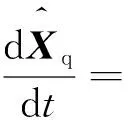
(11)

(12)
Based on the error equation, the error convergence equation can be expressed as
(13)
Then, the characteristic polynomial of the error matrix can be configured as follows:
det[sI-(Aq-LcqCq)]=(s+ωo1)(s2+
(14)
whereωo1determines the first-order pole,ξo2andωo2determine the complex poles associated with resonance, and the gains of theqaxis observer can be calculated as follows:
(15)
However, high observation poles need to be configured when the observation error is expected to be eliminated completely, resulting in the enlargement of noise sensitivity in state observers. According to the above state observervation model, the observed inverter current is chosen as the feedback variable for closed loop PI control. The improvement of observer dimensions and DOFs may help the promotion of dynamic characteristics in observation.
Aimed at removing the steady error, an extra state variable related to error integration is added into the state space vector, which can be expressed as
(16)
Then the associated vectors can be defined as
(17)
(18)
whereltqrepresents the reference gain andliqrepresents the integral gain. The dynamics of the improved observer with the extend state can be derived as
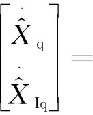
(19)
In this observation model, theqaxis converter voltages and grid voltages are given as the feedforward variables. From Eq.(19), the transfer function of the state space observer with the extended integration state can be expressed as
(20)
This detailed closed loop function is considerably complicated. Hence, when ignoring the imperceptible effect of capacitance in low frequency signals, the observation can be simplified as
(21)
Eventually, the observer parameters can be tuned as Eqs.(22) and (23) according to the required passband damping ratioξoand the above observation passbandωo.
(22)
(23)
In the same way, the gains of thedaxis observer can be obtained. In the actual system design, the poles of the observer are generally selected to be 2 to 6 times the poles of the controller, and the cutoff frequency of the observer should not exceed the Nyquist frequency.
3 Power Control Design
When finishing designing the inner current regulation, the structure of power loop can be shown as Fig.4. All in all, the bandwidth of outer loop should be less than that of inner loop. In this section, the PLL technology capturing the phase angle of grid voltage vectors and power regulation methods are discussed.
3.1 SRF-PLL with Loop Filter
In three-phase grid-oriented converters, the most commonly used phase-locked loop is SRF-PLL, as shown in Fig.5, and a loop filter is introduced before the PI regulator to filter out the corresponding harmonics in fundamental grid voltagesugqor corresponding negative sequence components for the elimination of the impact of grid voltages on SRF-PLL extraction phase angle. This method is called SRF-PLL based on loop filter.

Fig.4 Diagram of power closed-loop control

Fig.5 The diagram of SRF-PLL with the loop filter
It is revealed that three-phase grid voltages are transformed to the synchronous rotating voltages, where thedaxis andqaxis grid-tied voltages are
(24)
In Eq.(24),θ′is the phase angle extracted by SRF-PLL. When the real angleθis close to the estimated one, Eq.(24) can be expressed as
(25)
Therefore,ugdrepresents the observed grid voltage magnitude whileugqreflects the error between grid voltage real angle and estimated one. Based on the illustration in Fig.5, the transfer equation of PLL can be expressed as
(26)
When the controller gains are selected as Eqs. (27) and (28), the system can be equivalent to Eq.(29).
(27)
(28)
(29)
whereξpis the damping ratio andωpis the bandwidth of SRF-PLL.ξpis usually selected as 0.707 and the cutoff frequencyωpis often designed 5 to 10 times the fundamental frequency of grid.
3.2 Power Controller Design
In the dqcoordinates, active power and reactive power injecting into grid can be derived according to instantaneous power calculation principles:
(30)
In the case ofugq=0, the power calculation can be simplified as follows:
(31)
In this paper, PI controller is used to implement closed-loop power tracking control on the grid side. The PI parameters are characterized according to the requirement of power dynamics.
4 Simulation Results
Simulations were used to verify the proposed current control methods and power control methods. Specifications of the simulations are presented in Table 1, where the amplitude and frequency of grid-side voltage was selected as the corresponding constants.
4.1 Validation
In contrast with the performance of state space PI controller, a conventional PI current regulator with active damping is developed. The PI parameters are tuned based on classic system design principles, where the bandwidth corresponds with that of the proposed controller and the active damping ratio is selected in constrained conditions. Meanwhile, the LCL filter parameters selected by classic parameter design methods are applied in the simulation system.
The observation efficiency of the state space observer is displayed in the following section, in which only capacitor voltages and grid currents are discussed due to inverter currents measured directly by sensors. As can be seen in Fig.6, the observer observes the actual voltages and currents quickly and accurately respectively and attenuates the disturbing harmonics acting as low pass filters where the percentage of diminished noise components exceeds 80%.
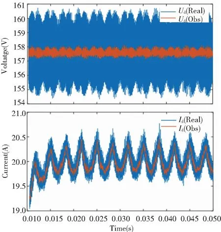
Fig.6 Comparison between measured dq axis voltages as well as currents and observed voltages and currents


Fig.7 Comparison of phase currents from state-space PI control and conventional PI with active damping

Fig.8 Comparison of dq axis currents from state-space PI control and conventional PI with active damping
4.2 Parameter Errors
Besides, the effect of the varying grid inductance was examined in this paper. The corresponding cases of the parameter deviationsΔLg/Lg=0.3 andΔLg/Lg=-0.3 were simulated, and the findings are displayed in Fig.9. The findings reveal that the grid inductance fluctuation has little influence on thedaxis current ripple, whose current fluctuation is less than 1% while theqaxis current may be influenced more seriously, whose current fluctuation is more than 50%. Overall, the power regulation system maintains its stability when the parameter varies, and the larger inductance may decrease the resonance frequency, contributing to better harmonic attenuation.

Fig.9 Simulated grid-current step response with parameter errors ΔLg/Lg=0.3 and ΔLg/Lg=-0.3
4.3 SRF-PLL Response
Simulations were implemented to demonstrate the effectiveness of the proposed power control method. The PLL bandwidth was set up as 1000 rad/s and the PLL damping ratio was 0.707. As shown in Fig.10, the SRF-PLL with the loop filter achieves fast and accurate phase tracking, which can meet the actual requirements, where the fundamental frequency of grid was selected as 50 Hz.

Fig.10 The tracking performance of SRF-PLL with loop filter
4.4 Power Tracking Response
Aimed to verify power closed loop regulation performance, the reference of active powerPrefand reactive powerQrefwere set as 6 kW and 0 kVar, respectively. The tracking differentiator was employed to smooth the references, eliminating the impact on the grid. Fig.11 reflects the power responses using PI current controllers with active damping, where the chattering magnitude of active power and reactive power steady responses is nearly 1000. Fig.12 shows the responses with state space controllers based on the extended Luenberger observation, in which both active power and reactive power achieve stable tracking without remarkable power error, whose magnitude is less than 200. Compared with responses in Fig.11, less fluctuation and more excellent power closed loop performance are acquired when state space current control strategies are applied. Fig.12 reveals that noise elimination from state space observer plays a more active role than filters after power calculation without state space observers.

Fig.11 Active power and reactive power response with PI controller based on active dampingwhen active power reference was set as 6 kW
Fig.13 Displays the current responses under above power conditions with state space control schemes and conventional PI schemes, respectively. In each graph, the current is 0.5 times the actual value while the grid voltage is 0.2 times the actual one. In terms of phase angle tracking, the current responses of the two methods have almost same phase angle compared with that of the phase A grid voltage. However, the proposed methods in this paper are much superior to PI methods in the harmonic suppression regardless of high order ones or low order ones whose current THD are 2.31% and 6.4%, respectively. Besides, to achieve similar responses just like the ones from state space controllers, considerably small active damping parallel visual resistance is employed in conventional PI systems, which inevitably gives rise to the amplification of noise, degrading the stability.

Fig.12 Active power and reactive power response with state space controller based on the extended Luenberger observer when active power reference was set as 6 kW
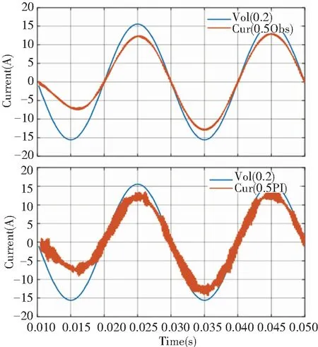
Fig.13 Phase current response with state space controller based on the extended Luenberger observer and PI controller with active damping(the blue represents the grid voltage and the red represents the current response)
Next, the reactive power reference was set as -2 kW at 0.05 s. Fig.14 and Fig.15 present the active and reactive power responses using the above two methods, respectively. Contrast with the active power in Fig.14 whose oscillation problems may become more serious due to the coupling between active power and reactive power, the active power in Fig.15 may be slightly affected by the increase of reactive power. Besides, reactive power harmonics in Fig.15 using proposed methods are much smaller than those in Fig.14, contributing to the improvement of system stability and dynamic characteristics.

Fig.14 Active power and reactive power response with PI controller based on active damping when reactive power reference was set as -2 kW
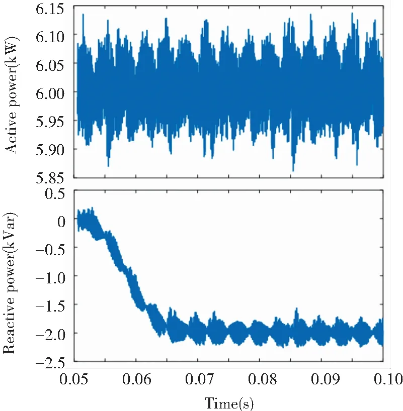
Fig.15 Active power and reactive power response with state space controller based on the extended Luenberger observer when reactive power reference was set as -2 kW
5 Conclusions
Currently, the grid-connected inverter technology with LCL filter is an important research direction of distributed power generation and new energy power generation. The main contribution of this article are as follows:
1)Aimed at overcoming poor current response caused by simplified methods neglecting the capacitors, this paper proposes a state space PI current regulation strategy based on the mathematical model of LCL-type grid-tied converters, which combines the state space methods’ disturbance-rejecting ability and the high efficiency of integrated control, bringing about the high precision control of grid current.
2)To avoid the application of current or voltage sensors, which may decrease the reliability and increase the cost, an extended Luenberger state observer for full-order observation of state variables is proposed whose parameters are designed by the polynomial equations approach, improving the design efficiency of the converter systems. Besides, the state observer also functions as the filter which strengthens systems’ ability to anti-interference.
Combined with the theoretical analysis above, a set of 6 kW simulation system was constructed and the effectiveness of the proposed methods is demonstrated eventually.
杂志排行
Journal of Harbin Institute of Technology(New Series)的其它文章
- Optimal Kinematics Design of MacPherson Suspension: Integrated Use of Grey Relational Analysis and Improved Entropy Weight Method
- Model-Free Predictive Control for a Kind of High Order Nonlinear Systems
- Research on Sound Absorption Method of Perforated Tube with Shunt Hedge
- Optimal Motion Planning of the Space Manipulator for Minimum Reaction Torque to Satellite
- Investigation on Liquid Breakup Regimes and Atomization Performance of Slinger
- Characteristics of Convection Heat Transfer in Power-Law Fluid Saturated Porous Media Channel
