Research on Sound Absorption Method of Perforated Tube with Shunt Hedge
2022-05-20RenqiZhangCongyunZhuGuofangDingandQibaiHuang
Renqi Zhang, Congyun Zhu*, Guofang Ding and Qibai Huang
(1. School of Mechanical Science and Engineering, Zhongyuan University of Technology, Zhengzhou 450007, China;2. School of Mechanical Science and Engineering, Huazhong University of Science and Technology, Wuhan 430074, China)
Abstract: The exhaust flow velocity of the engine is an important parameter affecting the comprehensive performance of the muffler. The exhaust flow velocity increases by the regenerated noise generated in the muffler, which makes the sound absorption effect of the muffler worse. In order to solve this problem, a sound absorption method was proposed to reduce the flow rate of exhaust air by diverting and hedging the exhaust air, so as to improve the sound absorption. First of all, the airflow into the muffler was shunted by a conical shunt unit. Subsequently, the airflow entered the cavity of the perforated tube through the hole on the perforated tube. When the airflow was offset in the cavity of the perforated tube, it could reduce the flow rate of the exhaust airflow and improve the sound absorption effect. It could be concluded that the influence factors and the characteristics of the transmission loss were obtained by dividing the anechoic sub units of the whole structure, calculating the transfer matrix, and analyzing the function relationship between the independent variable and the dependent variable of the transmission loss, and the theoretical model was verified by experiments. The results of the experiment showed that the proposed sound absorption method can keep the transmission loss at a stable state under the condition of high-speed exhaust flow. For example, when the inlet air velocity increases from 15 m/s to 45 m/s, the maximum reduction of transmission loss is 6.5 dB in the range of 0-3000 Hz, which proves that the structure has a good effect of sound absorption.
Keywords: regenerated noise; split-stream-rushing; rerforated tube; transmission loss
0 Introduction
The sound absorption technology which can improve the sound absorption effect through reducing the exhaust flow rate has been studied extensively and deeply in recent years. Munjal[1]analyzed the attenuation characteristic of expansion chamber with external intubation. Isshiki et al.[2]studied the relationship between current speed and acoustic characteristics through the method of numerical simulation. In 2009, Wu et al.[3]raised a new type of counteract and self-cancelling sound absorption structure and simulation and carried out experimental test. The result showed that the new sound absorption structure had a good sound absorption effect. Through the studies on reverse hedging new sound absorption structure by Shao[4], the specific parameters of silencing unit had a great impact on comprehensive ability. The study of Song et al.[5]on aerodynamic performance of split opposed muffler found that the speed of the air in split opposed muffler has decreased greatly after hedging so that the re-created noise decreased greatly. Through the study of Zhang et al.[6]on a kind of cone ring shunt sound absorption structure, it is found that the size of cone ring and cone angle is an important factor which influences the sound absorption ability. Yasuda et al.[7]proposed a simplified model based on the theory of one-dimensional CFD model, and simulated the tailpipe noise of exhaust muffler, and verified the results through experiments. Fan and Ji[8]developed a one-dimensional analysis method based on the transfer matrix method to analyze the sound attenuation characteristics of the three-pass muffler, and verified it through experiments. The results show that the average flow rate increases the transmission loss of the muffler at the pass frequency and reduces the sound attenuation in the intermediate frequency range. Bucciarelli et al.[9]analyzed the parameters of the muffler structure of the multilayer microperforated plate by means of the electro-acoustic equivalent circuit method, studied the relationship between the sound absorption performance of the multilayer microperforated plate and the structural parameters, which were verified by the impedance tube experiment. Carbajo et al.[10]proposed a kind of muffler with inclined hole for multi-layer perforated plate. The acoustic performance of inclined hole multi-layer perforated plate was predicted by fluid equivalence theory, and the predicted results were verified by experiments. Zhou et al.[11]studied the low-frequency sound absorption characteristics of double-layer perforated plate with fixed cavity under the action of biased current, and the results show that the velocity of biased current is the key parameter to determine the sound absorption performance of double-layer perforated plate structure. A fully coupled modal formula was proposed by Bravo[12]. Based on the proposed fully coupled modal formula, the effects of structural resonance on the absorption coefficient and transfer loss of multi-layer perforated plates were predicted and verified by experiments.
It can be seen that the sound absorption method based on shunt and offset has been widely studied in recent years. In this paper, a sound absorption method is proposed to reduce the airflow velocity and improve the sound absorption effect by offsetting the airflow in the perforated pipe. The flow velocity of the airflow after the offset was studied, and various factors affecting the transmission loss were analyzed, and the transmission loss of the whole structure was calculated by MATLAB. Finally, the important parameters affecting the transmission loss and the change of the transmission loss when the airflow velocity increases were verified by experiments.
1 Theoretical Model
Fig.1 shows the overall structure. The main components are cone-shaped splitter unit and perforated pipe. The diameter and length of the straight pipe from the entrance ared1andL1, respectively. The length of the cone-shaped splitter unit isL2, and its cone angle isα.The length of the perforated pipe isL3, and its diameter isd2, The diameter of the external cavity isd3. The diameter of the straight pipe from the exit isd4.The length of both ends of the perforation segment isL5andL6, respectively. The sound pressure of perforated pipe’s the external cavity isp1a, its particle vibration velocity isu1a.The sound pressure of perforated pipe’s the inner cavity isp1b, and its particle vibration velocity isu1b.

Fig.1 Diagram of overall structure
1.1 Principle of Interference Muffling
The principle of noise attenuation is shown in Fig 2. When the sound wave enters the muffler from the inlet, the sound wave travels along theX-axis. When the sound wave reaches the hole in the perforated tube, the sound wave travels through the hole to the inside of the perforated tube. At this point, the sound wave begins to travel along theY-axis. Since the structure of the muffler is axisymmetric, when the sound wave propagates along theYdirection, it has the same frequency with the sound wave of the opposite hole, and the phase difference is 1800. At this time, the two sound waves are interfered and silenced. After the interference and silencing, the sound energy is converted into heat energy, so as to achieve the effect of silencing.
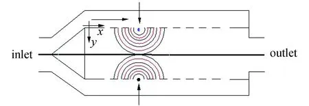
Fig. 2 Schematic chart of Interference muffler
1.2 Division of Anechoic Sub Units
As shown in Fig. 3, 1-2 is straight tube unit, 2-3 is conical shunt sub unit, 3-4 is perforated pipe, 4 is shrinking sub unit, 4-5 is straight tube unit. According to the propagation path of sound wave, the anechoic sub units among 1-5 are series connection. It comes to a conclusion that the transfer matrix of the whole sound absorption structure is as follows:
T=T12·T23·T34·T4·T45
(1)
In the formula,T12is 1-2 part of the transfer matrix,T23is 2-3 part of the transfer matrix,T34is 3-4 part of the transfer matrix.T4is 4 part of the transfer matrix, andT45is 4-5 part of the transfer matrix.

Fig.3 Diagram of unit division
1.3 Calculation of Transfer Matrix of Anechoic Sub Units
The transfer matrix of the inlet straight pipe anechoic sub-unit is[13]
(2)
wherekis the wave number andMis the Mach number.
The transfer matrix of the conical shunt sub unit is as follows[14]
(3a)
(3b)
(3c)

(3d)
(3e)
(3f)
(3g)
wherelis the length of the conical ring in the conical shunt sub unit, andl0is the distance between the entrance of the conical ring in the conical shunt sub unit and the vertex of the reverse extension line of the conical line.
The application of transfer matrix method is based on plane wave theory, so it is assumed that sound waves are plane waves and the propagation process is adiabatic. According to the law of conservation of mass and the law of conservation of momentum in fluid mechanics, the continuity equation and motion equation of the external cavity can be derived as follows[15]:
(4)
(5)
Inside the perforated pipe, there are
(6)
(7)
wherevis the velocity flowing into the inner cavity of the perforated pipe,tis time,ρis the density of gas in the process of sonic wave propagation, andρ0is the density of gas of static state.
Because the process of the sonic wave propagation is an adiabatic process, it can be inferred that[13]
(8)
wherec0is sound velocity.
The relative acoustic impedance rate of the perforated pipe is[13]
(9)
Letp(x,t)=p(x)ejωt. It can be concluded that
(10)
According to the empirical formula obtained by measuring the acoustic impedance of the perforated plate by Lee and Ih[16]under the condition of flow, there is
Z=Rh+jXh
(11)
Rh=a0(1+a1|f-f0|)(1+a2M)·
(1+a3dh)(1+a4tw)
(12)
Xh=b0(1+b1d)(1+b2tw)(1+b3M)(1+b4f)
(13)
f0=412(1+104M)/(1+274d)
(14)
wherea0=3.94×10⁻⁴,a1=7.84×10⁻³,a2=14.9,a3=296,a4=-127,b0=-6×10⁻³,b1=194,b2=432,b3=-17.2,b4=-6.62×10⁻³,Rhis the acoustic resistance,Xhis the acoustic reactance,dis the diameter of the perforated pipe, andtwis the thickness of the perforated pipe.
According to mass conservation equation, momentum equation and motion equation, it can be deduced that the acoustics equation of the perforated pipe is[17]
(15)
where
(16a)
(16b)
(17)
The solution of Eq. (15) can be expressed as
(18)
where [Ω] is a matrix composed of eigenvectors of matrixA,λis the eigenvalue of matrixA.
From Eq. (18), the relationship between sound pressure and particle vibration velocity atx=0 andx=Lacan be obtained:
(19)
where [R]=[Ω][E][Ω]-1
(20)
Inx=0 and and in the perforated pipe at a random positionx=Laplace, it has a boundary condition[18]:
(21)
It can be inferred that
p1a(0)=R11p1a(La)+R12ρ0c0u1a(La)+
(R13+jtan(kL6)R14)p1b(La)
(22a)
ρ0c0u1a(0)=R21p1a(La)+R22ρ0c0u1a(La)+
(R23+jtan(kL6)R24)P1b(La)
(22b)
p1b(0)=R31p1a(La)+R32ρ0c0u1a(La)+
(R33+jtan(kL6)R34)p1b(La)
(22c)
ρ0c0u1b(0)=R41p1a(La)+R42ρ0c0u1a(La)+
(R43+jtan(kL6)R44)P1b(La)
(22d)
p1a(0)=R11p1a(La)+R12ρ0c0u1a(La)+
(R13+jtan(kL6)R14)p1b(La)
(23a)
ρ0c0u1a(0)=R21p1a(La)+R22ρ0c0u1a(La)+
(R23+jtan(kL6)R24)p1b(La)
(23b)
p1b(0)=R31p1a(La)+R32ρ0c0u1a(La)+
(R33+jtan(kL6)R34)p1b(La)
(23c)
-jtan(kL5)p1b(0)=R41p1a(La)+R42ρ0c0u1a(La)+
(R43+jtan(kL6)R44)p1b(La)
(23d)
Subtract Eq. (23). There is
(R41+jtan(kL5)R31)+(R42+jtan(kL5)R32)
ρ0c0U1a(L3)+[R43+jtan(kL6)R44+
jtan(kL5)(R33+jtan(kL6)R34)]P1b(La)=0
(24)
Let
Q1=R41+jtan(kL5)R31
Q2=R42+jtan(kL5)R32
Q3=R43+jtan(kL6)R44+
jtan(kL5)(R33+jtan(kL6)R34)
(25)
Eq. (24) can be written as

(26)
Substitute Eq. (25) into Eq. (23). It can be inferred that

(27a)

(27b)
Therefore, it indicates that the transfer matrix of the perforated pipe is
(28)
where
(29a)
(29b)
(29c)
(29d)
It can be concluded that the transfer matrix of Eq. (28) isT34.
The transfer matrix of the shrinking sub units is[13]
(30)
whereSandl′ are the length and cross-section area of the contraction cavity.
(31)
The transfer matrix of the straight pipe anechoic sub units is[13]
(32)
2 Theoretical Calculation
The calculation formula of the transmission loss is[14]
(33)
whereA3,B3,C3,d3are the transfer matrix elements,mis the ratio of exit area to entrance area.
According to the analysis above, the parameters influencing transmission loss are the length of both ends of perforated sectionL5andL6, diameter of external chamberd2, diameter of perforated piped3, and the porosityφThe following calculates the changes of transmission loss curve when parameters change.
When the length of both ends of perforated sectionL5andL6changes, the changes of transmission loss curves are shown in Fig. 4.
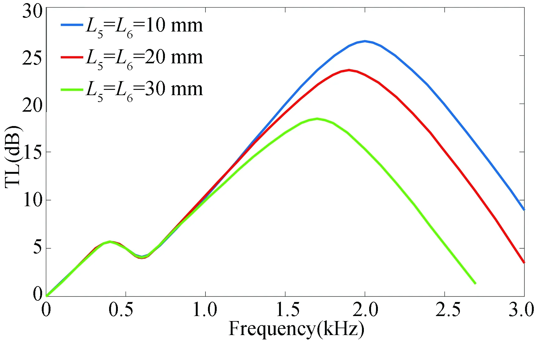
Fig.4 Overall transmission loss curves of divergent offset perforated pipe
When the diameter of external chamberd3remain the same, diameter of perforated piped2changes. The changes of transmission loss curves are shown in Fig. 5.
When the diameter of perforated piped2remains the same, diameter of external chamberd3changes. The changes of transmission loss curves are shown in Fig. 6.
When the porosityφhanges, the changes of transmission loss curves are shown in Fig. 7.
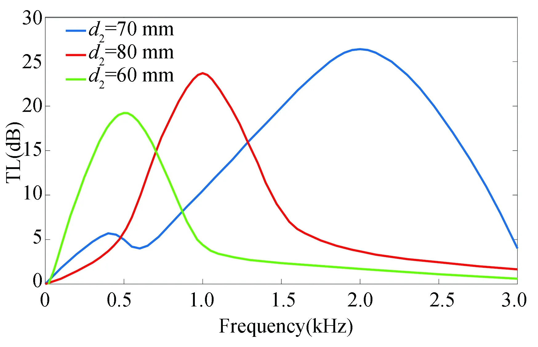
Fig. 5 Overall transmission loss curves of divergent offset perforated pipe

Fig. 6 Overall transmission loss curves of divergent offset perforated pipe

Fig. 7 Overall transmission loss curves of divergent offset perforated pipe
3 Experimental Verification
3.1 Experimental Methods
In the experiment of transmission loss, the two-load method is adopted, the sound source position is fixed, and the quadrupole parameters are solved by establishing equations by changing the impedance condition at the outlet.
As shown in Fig. 8,piis the incident sound wave at the inlet,pris the reflected sound wave at the inlet,pi1is the incident sound wave at the outlet, andpr1is the reflected sound wave at the outlet. The sound wave transmission relationship at both ends of the element to be tested is as follows:


Fig.8 Perforated plate structure
(34)
When the constraint condition is that the outlet is a non-reflective end andpr1=0, the calculation formula of transmission loss TL is as follows[19]:
(35)
In general, it is difficult to obtain the experimental condition that the outlet is a non-reflective end, so the outlet has two different impedance conditions, and two equations are obtained, and the simultaneous equations solveT11.When there is no impedance at the outlet, the sound wave transmission relationship at both ends of the element to be tested is as follows:
(36)
When there is an impedance at the outlet, the sound wave transmission relationship at both ends of the element to be tested is as follows:
(37)
With Eqs. (36) and (37), it can be figured out that
(38)
By changing the acoustic impedance at the outlet, the sound pressure values of two groups of incident waves and reflected waves are measured by four microphones, and the transmission loss TL can be solved by substituting the sound pressure values into the above formula.
3.2 Experimental Results
When the lengthL5andL6at both ends of the perforation segment changes, the comparison of the transmission loss obtained in the experiment and the result calculated by the formula are shown in Fig. 9.
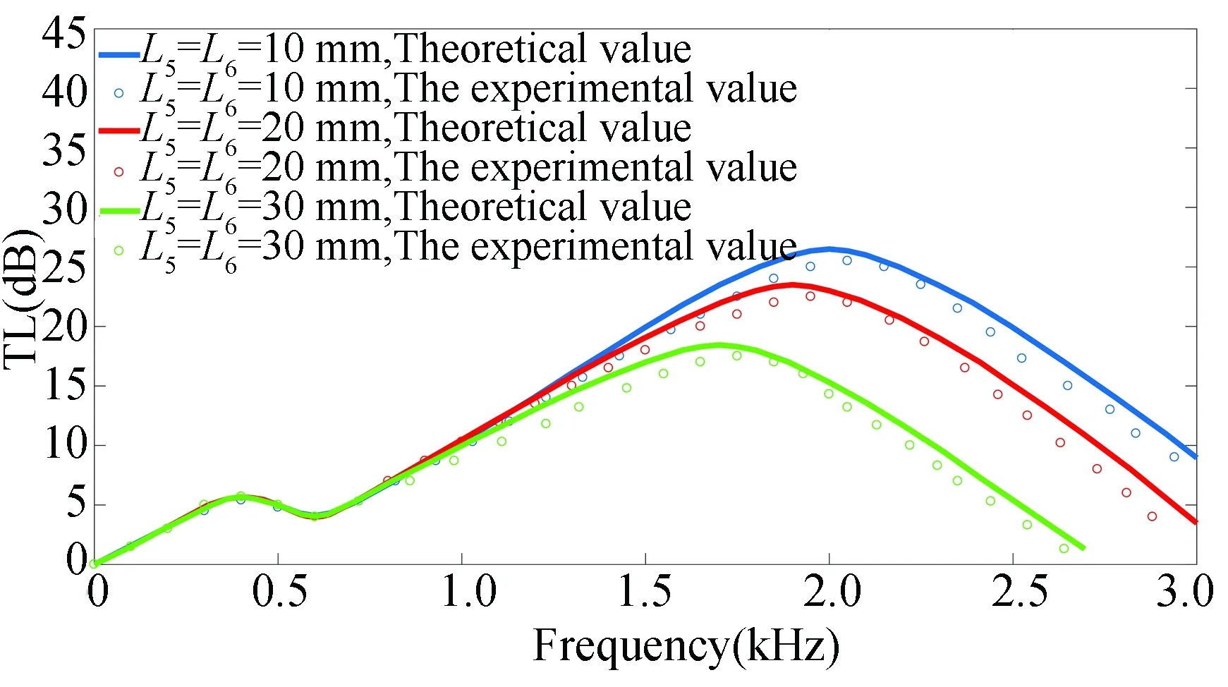
Fig. 9 Comparison of transmission loss
When diameter of the external cavityd3remains the same, the diameter of the perforated piped2changes. The comparison of the transmission loss obtained in the experiment and the result calculated by the formula are shown in Fig.10.

Fig. 10 Comparison of transmission loss
When diameter of the perforated piped2remains the same, diameter of the external cavityd3changes. The comparison of the transmission loss obtained in the experiment and the result calculated by the formula are shown in Fig. 11.
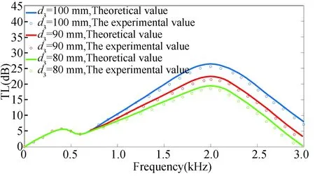
Fig.11 Comparison of transmission loss
When the porosityφhanges, the comparison of the transmission loss obtained in the experiment and the result calculated by the formula are shown in Fig.12.
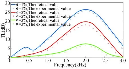
Fig. 12 Comparison of transmission loss
When the airflow velocity of the entrance changes, the comparison of the transmission loss obtained in the experiment and the result calculated by the formula are shown in Fig. 13.
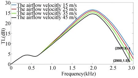
Fig.13 Comparison of transmission loss
3.3 Analysis on Experimental Results
According to Fig. 8, when the length of both ends of perforated sectionL5andL6decreases, transmission loss increases. It is because with the increase of length of perforated pipe, the number of holes increases, and the effect of air flow hedge strengthens, which causes the transmission loss to increase.
According to Fig.10, when the diameter of external chamberd3remains the same, the diameter of perforated piped2decreases gradually, the peak value of transmission loss moves to low frequency range, which results from the fact that as the diameter of perforated pipe decreases after the air flow hedge of the holes, the air flow speed increases, re-created noise gets higher, and it has little influence on low frequency range while has bigger influence on high frequency range.
According to Fig.11, when the diameterd2of the perforated pipe is constant and the diameterd3of the external cavity decreases, the transmission loss decreases, which results from the fact that with the decrease of the diameter of the external cavity, the gap between the external cavity and the perforated pipe decreases, and the shunted airflow cannot be fully decelerated in the external cavity, and with the decrease of the diameter of the external cavity, the flow velocity of the shunted airflow will gradually increase, resulting in a decrease in transmission loss.
According to Fig.12, when the porosityφncreases, the transmission loss decreases, which results from the fact that as the porosityφincreases, the acoustical mass in the small pore decreases, which makes the sound impedance of the perforated pipe decrease, thus reducing the sound absorption effect.
According to Fig.13, when the airflow velocity of the entrance increases, the transmission loss decreases, which results from the fact that the diameter of the perforated tube, the length of the perforated section and porosity are fixed values. The hedging effect does not increase when it reaches the peak. When the the airflow velocity of the entrance increases, the regeneration noise increases, the transmission loss decreases, but the reduction range is smaller. However, it can still guarantee good functions of absorbent.
3.4 Analysis on Experimental Error
The overall trend of the experimental results is basically consistent with the theoretical calculation results, but there is some error. This is because during the experiment, due to the rough inner wall of the muffler sample, the transition area at the connection of each muffler unit failed to achieve smooth transition, resulting in resistance in these areas, affecting the muffler effect. Besides, due to the interference of the external environment, there will be a certain amount of background noise. The existence of background noise will reduce the measurement accuracy.
4 Conclusions
The air in external chamber slows down fully after the conical shunt units split it. After this, it goes hedging through perforated pipe. The flow speed after hedging decreases greatly, which decreases the generation of re-created noise. During the hedging process of the air, the acoustic energy attenuated mutually, thus strengthens the sound absorption effect.
The variables that affect the transmission loss are verified by experiments. The experimental results show that the length of both ends of the perforated sectionL5andL6, the diameterd2of the perforated pipe, the diameterd3of the external cavity, and porosityφhave significant effects on the transmission loss. Only by reasonably selecting the above structural parameters can better sound absorption effect be guaranteed.
When the inlet air velocity increases from 15 m/s to 45 m/s, the maximum reduction of transmission loss is 6.5 dB in the range of 0-3000 Hz, which proves that the structure has a good effect of sound absorption.
杂志排行
Journal of Harbin Institute of Technology(New Series)的其它文章
- Finite Element Modeling and Vibration Analysis of Sprag Clutch-Flexible Rotor System
- Molecular Dynamics Simulation on Friction and Thermal Properties of FCC Copper in Nanoscale Sliding Contacts
- Numerical Modeling of a New Flight Simulator Enabling Continuous 360-Degree Spinning and Translational Motion
- Characteristics of Convection Heat Transfer in Power-Law Fluid Saturated Porous Media Channel
- Investigation on Liquid Breakup Regimes and Atomization Performance of Slinger
- Optimal Motion Planning of the Space Manipulator for Minimum Reaction Torque to Satellite
