An analysis on a rigid-flexible coupling system of an oscillating mass and a rotating disk
2022-03-04JinLiuKiZhngZhnfngLiu
Jin Liu, Ki Zhng, Zhnfng Liu,c,*
a College of Aerospace Engineering, Chongqing University, Chongqing 400040, China
b CSSC Haizhuang Wind Power Co.,LTD, Chongqing 401123, China
c State Key Laboratory of Ultrasound in Medicine and Engineering, Chongqing Medical University, Chongqing 400016, China
Keywords:Rigid-flexible coupling Additional inertial forces Nonlinear differential equation Motion trajectory
ABSTRACT A mass-rod-disk system consisting of an oscillating mass attached to a rigid rotating disk by an elastic rod is designed to study rigid-flexible coupling mechanism. Suppose the rod is lightweight and has enough stiffness, the theorems of linear momentum and angular momentum are applied to the mass-rod-disk system based on the kinematic description of the system. With respect to two deflections of the mass and one angular velocity of the system, a group of nonlinear differential equations are established where the tangential inertial force, centrifugal force, Coriolis force as well as the moments of additional inertial forces take important effects on the dynamic response. For the sake of description, these three types of inertial forces mentioned before are referred to as additional inertial forces in this paper. The horizontal deflections of the mass and the angular velocity of the disk rotating about a fixed-axis are numerically solved for the prescribed external torque. The oscillating trajectory of the mass is deeply influenced by the additional inertial forces, meanwhile the dynamic fluctuations of the angular velocity and rotary inertia of the system are strongly affected by the mass oscillation.
This paper describes the rigid-flexible coupling mechanism and its influence on the dynamic response of a simple rotating system. For a rotating structure such as a rotating compressor, flexible appendages undergo elastic deformation and large-scale rotation. The coupling between the deformation and overall rotation of the structure results in additional inertial forces, which are further imposed on the rotating structure; as a result, the dynamic characteristics and response of the rotating structure are completely different from those of a structure that is not undergoing overall rotation. Simultaneously, elastic deformation changes the rotary inertia of the rotating structure; thus, the angular velocity is different from that of a structure that is not being deformed.
Considerable research has been conducted on the dynamics of rotating cantilever beams [1–6], with their natural frequencies,mode shapes, and dynamic responses being topics of interest. In particular, dynamic stiffening and system stability have been extensively investigated [7–9]. The dynamic stability of a pretwisted cantilever was examined by S. Ahmad [10]. Xiao et al. [11] investigated a nonlinear dynamic model of a rotating Euler–Bernoulli beam with a flexible support. Shabana [12] and Schiehlen [14] reviewed the development of methods for modeling and numerically simulating multibody system dynamics, and Wasfy and Noor[13] summarized the computational modeling of flexible multibody systems. Nevertheless, the rigid-flexible coupling mechanisms of both single rotating components and complex rotating structures and their solution strategies continue to be the subjects of extensive study [15–20]. To understand the rigid-flexible coupling mechanisms of such structures, it is conducive to consider a simple but feasible system in which elastic deformation is dynamically coupled with large-scale rotation. In this context, studying the dynamics of a mass-rod-disk system is particularly beneficial for understanding the dynamics of complex rigid-flexible coupled systems.
Previous studies have investigated a mass attached to a rotating flexible rod [21–22]. In general, a set of nonlinear differential equations governing the motion of the mass was established for linearly elastic rods undergoing constant rigid rotation, and the Coriolis effect on the system response was especially analyzed. In particular, Brons et al. [23] demonstrated that the periodic motion of the mass followed a figure-eight shaped curve, while Liu et al.[24] noted that a petal pattern formed for the deflection trajectory of a mass . However, the interaction between the mass deflection and overall rotation, notably, how the deflection of the mass affects the overall rotation of the system, has not been satisfactorily answered.

Fig. 1. A flexible rod with a mass on one end is mounted onto a rotating rigid disk.

Fig. 2. The rotating base vectors and the reference base vectors in fixed-point rotation.
In this paper, a coupled mass-rod-disk system in which the mass is subjected to elastic deformation and overall rotation is investigated. The mass is clamped to a flexible rod, and the latter of the rod is fixed to a rigid circular disk rotating about a fixed axis. The mass of the rod is negligible compared to the mass and the disk and it undergoes sufficiently small deformation such that a two-dimensional deflection of the mass in the plane of rotation is preserved. A kinematic description of the mass in reference to the coordinate systems before and after rotation is analyzed, and a group of governing equations is developed in terms of two deflections of the mass and the angular velocity. The influence of additional inertial forces on the dynamic response and the effect of the deflection of the mass on the overall rotation are examined by numerical examples.
A massmis fixed to the free end of an elastic rod, and the other end of the rod is mounted onto a rigid circular disk that may rotate around its center, as shown in Fig. 1. For the sake of simplicity, it is assumed that the long, thin rod is elastic and massless.
To evaluate the kinematics of the mass, two coordinate systems must be introduced. A rotating coordinate system {e1,e2,e3}is fixed to the circular disk to observe the oscillation of the mass,and the origin is positioned at the center of the disk. In addition, a reference (inertial) coordinate system{ˆe1,ˆe2,ˆe3} is kept motionless but with the same origin. In the case of rigid body fixed-point rotation, the rotating system and the reference system are illustrated in Fig. 2.
There are two groups of base vectors. The base vectors of the reference system are expressed in terms of the base vectors of the rotating system, or vice versa. Due to the commutativity of the vector dot product, we have


Fig. 3. A flexible rod with a mass is mounted onto a rotating rigid disk.
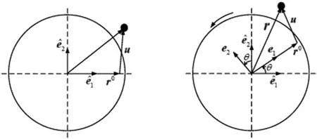
Fig. 4. The position of the mass in two coordinate systems before and after rotation.
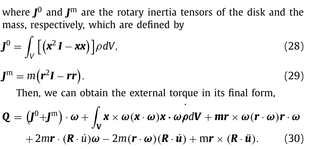
For the prescribed external torque, the angular velocity vector and the mass deflection are both unknown variables. The above equation must be combined with Eq. (18) to form a problem with a closed-form solution.
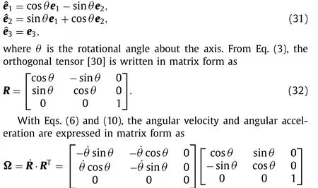
Without loss of generality, we consider that the circular disk rotates around a fixed axis, as shown in Fig. 3. The deflection of the mass is confined to the plane of rotation, and the position of the mass before and after rotation is described in Fig. 4. Here, we study how the oscillation of the mass affects the angular velocity of the disk and how the rotation of the disk influences the mass deflection. With the help of Eq. (1), we have

Therefore, in addition to the restoring force, the mass experiences four kinds of inertial forces: a tangential inertial force, centrifugal force, Coriolis force and relative inertial force. According to the Euler–Bernoulli beam model, the deflection of the bent rod is determined by
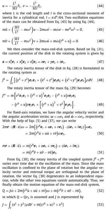
Therefore, the oscillation of the mass and rotation of the disk are governed by a set of strong nonlinear motion Eqs. (45),(46) and (52), in which three unknowns, namely,u,vandω, must be solved.
The deflection of the mass and rotation of the rigid disk are fundamental in determining the dynamic response of the massrod-disk system. The parameters of the mass, rod and disk are given in Table 1. A given external torque on the circular disk changes with time asQ=2×10⁻³sin(0.2πt)N·m, and the acting time is 5.0 seconds.
Two deflections of the mass and an angular velocity are solved from the set of Eqs. (45–46) and (52) with the use of MATLAB. The time-varying radial and circumferential deflections of the mass are shown in Figs. 5 and 6. Note that the deflections of the mass are observed in the rotating system because of local elastic deformation. In addition, the radial deflection is much larger than the circumferential deflection, and the mass undergoes rapid growth and local elastic oscillation relative to the circular disk.
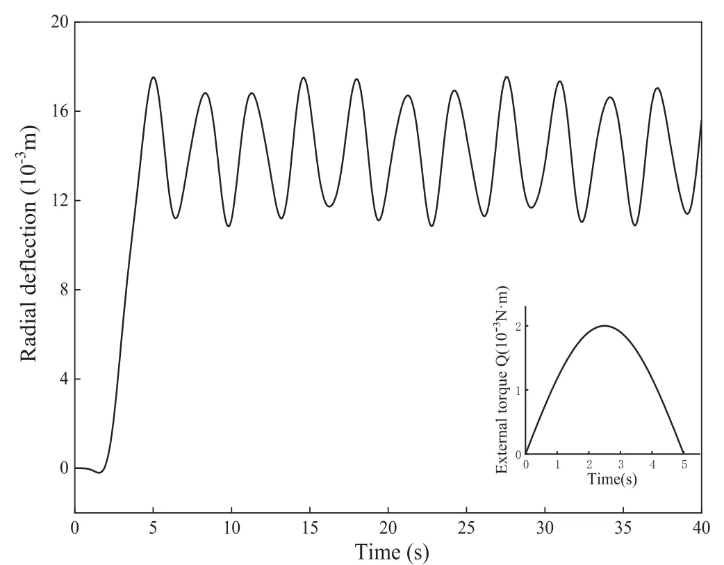
Fig. 5. The time-varying radial deflection of the mass in the rotating coordinate system.
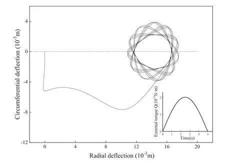
Fig. 7. The deflection trajectory of the mass in the rotating coordinate system within 20.0 seconds.
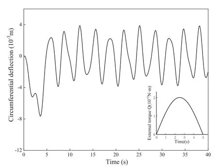
Fig. 6. The time-varying circumferential deflection of the mass in the rotating coordinate system.

Table 1 The parameters of the mass-rod-disk system
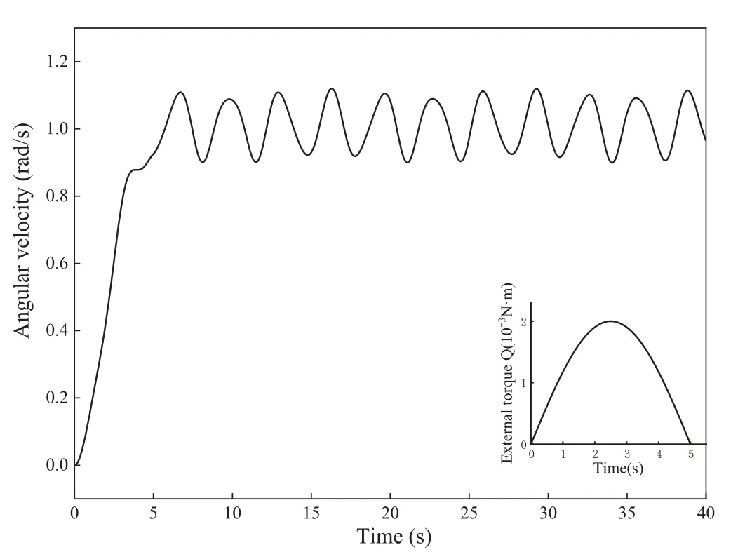
Fig. 8. The time-varying angular velocity of the rigid disk.

Fig. 9. The time-varying rotary inertia of the rigid-flexible coupled system.
The deflection trajectory of the mass in the rotating coordinate system is shown in Fig. 7. Interestingly, when the external torque is applied, the mass passes through a curved trajectory relative to the disk. Once the external torque vanishes, the mass follows a petalshaped oscillation trajectory, and the mass oscillates around a new balanced point away from its initial position. The angular velocity of the rigid disk changes with time, as depicted in Fig. 8. At the beginning, the angular velocity of the disk grows rapidly and then fluctuates with time. Due to deflections of the mass, the rotary inertia of the system changes, as shown in Fig. 9. As seen in the above results, the oscillation of the mass strongly affects the rotation of the system, and vice versa. This result explains the rigidflexible coupling behavior of the mass-rod-disk system.

Fig. 10. The time-varying radial deflection of the mass in the rotating coordinate system.

Fig. 11. The time-varying circumferential deflection of the mass in the rotating coordinate system.
Next, we observe the dynamic response of the system when the rotary inertia J0is decreased 10 times while the other parameters remain unchanged. The radial deflection is greatly increased in Fig. 10 compared to that in Fig. 5, whereas the magnitude of the circumferential deflection in Fig. 11 is roughly the same as that in Fig. 6. However, the oscillation frequencies of the radial and circumferential deflections are largely increased, as shown in Figs. 10 and 11.
The deflection trajectory of the mass in the rotating coordinate system is depicted in Fig. 12. During the loading of the external torque, the mass passes through a curved trajectory. When the external torque vanishes, the mass creates a new pattern of deflection trajectories, such as flower baskets. As the rotary inertia of the disk decreases, the angular velocity of the disk fluctuates much more dramatically, as shown in Fig. 13. Compared to the angular velocity in Fig. 8, the absolute value of the angular velocity is certainly increased, but the oscillation frequency is remarkably larger.Correspondingly, the change in the rotary inertia of the system is stronger, as shown in Fig. 14. Accordingly, the rotary inertia of the disk clearly plays an important role in the dynamic response of the coupled system.
It is therefore necessary to examine the influence of the external torque on the dynamic response of the system. The system parameters are listed in Table 1, but the external torque on the disk is given as
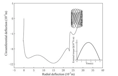
Fig. 12. The deflection trajectory of the mass in the rotating coordinate system within 20.0 seconds.
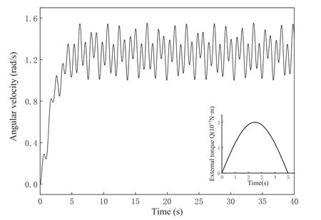
Fig. 13. The time-varying angular velocity of the rigid disk.
The external torque lasts 7.0 seconds. As shown in Figs. 15 and 16, a sharp pulse occurs in the radial and circumferential deflections of the mass before 3.0 seconds. However, after 7.0 seconds,the oscillations of the radial and circumferential deflections become relatively stable. In the deflection trajectory relative to the disk plotted in Fig. 17, the mass passes through an irregular curved trajectory before 7.0 seconds. After 7.0 seconds, the mass produces a trajectory pattern similar to an ellipse, where the major axis is oriented along the radius of the disk.
The change in the angular velocity of the disk exhibits interesting behavior. As shown in Fig. 18, the angular velocity grows rapidly, drops quickly to zero, and then increases again up to a fluctuating state. Moreover, the change in the rotary inertia of the coupled system is described in Fig. 19, showing that an impulse forms before 3.0 seconds. The change in the rotary inertia of the system completely coincides with the change in the mass deflection.
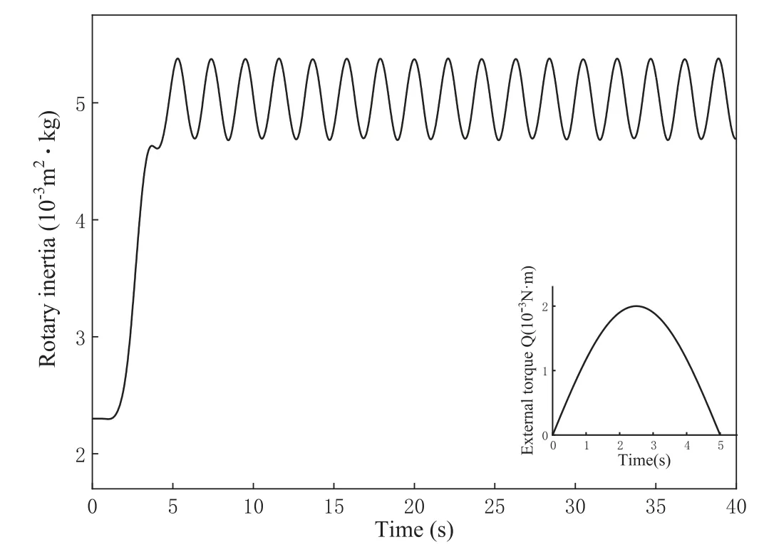
Fig. 14. The time-varying rotary inertia of the rigid-flexible coupled system.

Fig. 15. The time-varying radial deflection of the mass in the rotating coordinate system.
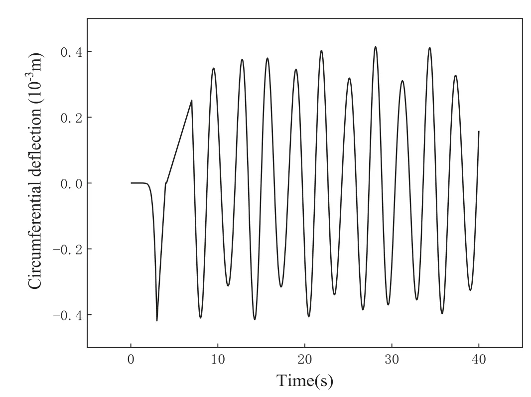
Fig. 16. The time-varying circumferential deflection of the mass in the rotating coordinate system.

Fig. 17. The deflection trajectory of the mass in the rotating coordinate system within 20.0 seconds.

Fig. 18. The time-varying angular velocity of the rigid disk.

Fig. 19. The time-varying rotary inertia of the rigid-flexible coupled system
Rigid-flexible coupling mechanism of the mass-rod-disk system is clearly elucidated. In the case of fixed-axis rotation, the deflection of the mass and the angular velocity of the disk are satisfied with a set of nonlinear differential equations. Three additional inertial forces, namely, the Coriolis force, the tangential inertial force and the centrifugal force as well as the moments of additional inertial forces play an important role in the coupling dynamic response. Dynamic deflection of the mass is largely affected by the angular velocity of the disk, and the changes of angular velocity of the disk and rotary inertia of the system are associated with deflection of the mass. It is noted that the deflection trajectory of the mass relative to the disk follows an impressive curve. These findings are undoubtedly beneficial for understanding complex rigidflexible coupled systems.
Declaration of Competing Interest
We declare that we have no financial and personal relationships with other people or organizations that can inappropriately influence our work, there is no professional or other personal interest of any nature or kind in any product, service and/or company that could be construed as influencing the position presented in, or the review of, the manuscript entitled.
Acknowledgements
This work is supported by the National Natural Science Foundations of China (No. 11772071), NSAF (No. U1830115) and the Fundamental Research Funds for the Central Universities (No.2020CDJQY-Z004).
杂志排行
Theoretical & Applied Mechanics Letters的其它文章
- A machine learning based solver for pressure Poisson equations
- Optimization for vibro-impact nonlinear energy sink under random excitation
- Performance improvement of the stochastic-resonance-based tri-stable energy harvester under random rotational vibration
- Simulation and experimental analysis of melt pool evolution in laser engineered net shaping
- Clamping force of a multilayered cylindrical clamper with internal friction
- Hydrothermal analysis of hybrid nanofluid flow on a vertical plate by considering slip condition
