Structural Dynamic Optimization for Flexible Beam of Helicopter Rotor Based on GA
2022-02-10,,
,,
(1.National Key Laboratory of Rotorcraft Aeromechanics, Nanjing University of Aeronautics and Astronautics, Nanjing 210016, P. R. China;2.Equipment Department, China Aero-Polytechnology Establishment, Beijing 100028, P.R.China)
Abstract: As one of the most important steps in the design of bearing-less rotor systems, the design of flexible beam has received much research attention. Because of the very complex working environment of helicopter, the flexible beam should satisfy both the strength and dynamic requirements. However, traditional optimization research focused only on either the strength or dynamical characteristics. To sufficiently improve the performance of the flexible beam, both aspects must be considered. This paper proposes a two-stage optimization method based on the Hamilton variational principle: Variational asymptotic beam section analysis (VABS) program and genetic algorithm (GA). Consequently, a two-part analysis model based on the Hamilton variational principle and VABS is established to calculate section characteristics and structural dynamics characteristics, respectively. Subsequently, the two parts are combined to establish a two-stage optimization process and search with GA to obtain the best dynamic characteristics combinations. Based on the primary optimization results, the section characteristics of the flexible beam are further optimized using GA. The optimization results show that the torsional stiffness decreases by 36.1% compared with the full 0° laying scheme without optimization and the dynamic requirements are achieved. The natural frequencies of flapping and torsion meet the requirements(0.5 away from the passing frequencies of the blade, 0.25 away from the excitation force frequency, and the flapping and torsion frequencies keep a corresponding distance). The results indicate that the optimization method can significantly improve the performance of the flexible beam.
Key words:bearing-less rotor system; flexible beam; dynamic optimization; Hamilton variational principle; variational asymptopic beam section analysis; genetic algorithm(GA)
0 Introduction
Bearing-less rotor systems are widely used in small and medium size helicopters because of their simple structure, light weight, good maneuverability and high reliability. For example, the MD-900, RAH-66 and EC-135 have been proved to have higher flight performance than helicopters with ordinary configuration. The flexible beam is the main load-bearing part of a bearing-less rotor system, which bears most centrifugal force, flapping moments and lagging moments. However, traditional optimization research focused only on either the strength or dynamical characteristics in designing flexible beam. To sufficiently improve the performance of the flexible beam, both aspects must be considered[1].
Existing related researches focus on two aspects: Bearing-less rotor designs and optimization methods. This paper focuses on the optimization methods.
Many kinds of schemes for the design of bearing-less rotor and flexible beam have been proposed since the 1960s. A “cross beam” bearing-less rotor scheme, in which the main blade bearing part was a one-way carbon fiber girder and the root of the skin was a hollow twist tube, was proposed[2]. French Aerospace[2]proposed a three-way flexible hub scheme with three arms of the hub made of glass fiber reinforced plastic and oval-shaped flexible beam section. Boeing-Votel Company[2]proposed a double-open section flexible beam structure made of carbon fiber. The inner and outer ends of the beam were connected to the connecting plate on the rotor shaft and the blade, respectively. McDonnell Douglas Aerospace Company[2]developed an automatic design program for bearing-less rotor in 1989, including the dynamic optimization program HUBFLEX for composite flexible beam. The bearingless rotor was validated in a wind tunnel in 1992 and fitted to the MD900 helicopter[2]. Westland Helicopter Company and Bristol University[3]jointly developed a bearing-less flexible beam of complex section in 2002. Ref.[4] proposed a finite element analysis formula for calculating section stiffness characteristics of composite flexible beams based on the Hamilton principle in 1998. Ref.[5] researched the influence of lamination angle in 2004. Many other researches have been conducted in recent year[6-11].
Some researches on structural dynamic optimization of the flexible beam have been published since the 1970s. Bielawa[12]first applied the structural dynamics optimization method to the design of a flexible beam in 1971. Lim et al.[13]established an aeroelasticity model of the flexible beam. Ganguli and Chopra[14]optimized the composite blades to reduce the vibration load and dynamic stress under two constraints: Aeroelasticity stability and natural frequencies. Pierson et al.[15]applied the gradient projection algorithm to the vibration optimization of cantilever beam and transformed it into an optimal control problem in 1977. Vavrick et al.[16]proposed the frequency optimization problem of free-torsional vibration of a thin-walled cylinder in 1978. Ref.[17] researched the structural dynamic optimization technology of a C-beam composite blade, and established a design-oriented optimization model in 1998. Refs.[18-19] researched the approaches and objectives of optimal design for vibration reduction on helicopter rotor blade in 1999 and 2001, respectively. Many other researches have been conducted in recent years[20-25].
In previous optimization studies, the objective was to optimize either strength or structural dynamic characteristics but not both. This paper proposes a two-stage optimization method that simultaneously includes two aspects based on the Hamilton variational principle: Variational asymptotic beam section (VABS) program and genetic algorithm (GA). Two parts of the analysis model are established based on VABS and the Hamilton variational principle to calculate section characteristics and structural dynamics characteristics, respectively. Subsequently, a two-stage optimization process is established. First, GA is used as an optimization tool to search the best combination of dynamics characteristics. Second, based on the primary optimization results, the section characteristics of the flexible beam are optimized again using GA. The optimization results are validated using the Tsai-Wu tensor theory. The dynamic characteristics of the flexible beam blade under working speed are validated, and a resonance diagram is drawn within the working speed range to validate the rationality of the optimization results.
1 Section Characteristics Analysis
The variational progressive beam section analysis is a useful method for more efficient and accurate calculation and analysis of structure, especially of the composite beams.
The relationship between design parameters and section characteristic parameters (mass and stiffness) is established using 2-D section characteristic analysis. The section characteristic parameters are used as intermediate parameters to connect beam structure and rotor dynamic characteristic parameters.
A flow chart of the section characteristics analysis model of flexible beam is shown in Fig.1. The process included two main steps: Parametric modeling and the VABS program.

Fig.1 Flow chart of section characteristics analysis model
1.1 Parametric modeling
According to different structural characteristics of the bearing-less flexible beam, sections are divided into five parts: Rotor hub connecting section, rotor hub transition section, torsional deformation section, blade transition section and blade connecting section, as shown in Fig.2.

Fig.2 Typical structure of a flexible beam
The following set of parameters is used[26]

whereCkis the parameterized variable set of thekth section, including the width of the rectangular sectionak, the thickness of the sectionbk, and the lamination angle of the sectionθk.
1.1.1 Parameters of nodes
A rectangular section is parameterized. With the center of the rectangle as the point of origin (0,0), its coordinates can be expressed as

1.1.2 Gridding cells
The nodes obtained are connected in sequence to form a quadrilateral mesh, and the elements are numbered for use in the preprocessing file. The file is used to calculate the VABS program to obtain the section characteristics of the flexible beam. The parametric geometric modeling of the rectangular section and cross section are shown in Fig.3.

Fig.3 Geometric modeling of flexible beam
1.1.3 Node properties
Three coordinates are used: A global coordinate to define geometric parameters (x1,x2,x3),a material coordinate to define material properties (e1,e2,e3),and an intermediate transformation coordinate to define lamination parameters (y1,y2,y3).θ1,θeandθkiare the unit shape and position.θeis the designable lamination angle, andθkithe lamination angle defined in the design parameter set, respectively. As shown in Fig.4, the parameters are defined as the coordinates[27].

Fig.4 Coordinate systems for the definition of VABS lamination parameters
1.2 VABS
VABS analysis is a method widely used for composite beam analysis. VABS is based on the variation asymptotic method (VAM). The process of VAM involved replacing a 3-D model of the flexible structure with a 2-D section model and a 1-D nonlinear beam model. The stiffness matrix obtained using the 2-D cross-section model analysis represents the parameters of the 1-D nonlinear beam model[24]. The warping field from beam model and section model could restore the section characteristics of the original 3-D model.
According to the rotation tensor decomposition theory, the Jaumann-Biot-Cauchy strain in the coordinate systembis derived to obtain the 3-D strain field

whereΓαrepresents the strain field of characteristic length of the composite beam section,Γεˉthe strain field of 1-D generalized strain,Γlthe strain field of length of the beam andΓRthe strain field of characteristic radius at the initial bending rate. The matrix expressions used are as previously described[25]:Γ=[Γ11,2Γ12,2Γ13,Γ22,2Γ23,Γ33]T,w=[w1,w2,w3]TandΓα,Γεˉ,ΓR,Γl.
Strain energy can be calculated using the following section strain energy expression

whereDis the material stiffness coefficient matrix of the section.
The constitutive relation equation can be obtained as

The stiffness coefficient matrix can be expressed as

For finite element modeling of flexible beam with rectangular section, the section is divided into finite element mesh and assigned material properties. The design parameters of the section include geometric, lamination and material parameters. The characteristic parameters of the section inclucle the mass and stiffness distributions of the section obtained from the VABS program.
1.3 Validation of VABS
The calculation results of the beams are verified based on the following assumptions[28]:
(1) The boundary between single layers is ideal. As an overall structural plate, the thickness of the boundary layer can be ignored, and no deformation occurs on its own.
(2) The thickness of each layer is uniform, and is made of linear elastic orthotropic material.
(3) The positive strain in the thickness direction of the laminated beam can be ignored.
(4) The bending of the beam is always in the plane.
(5) The deformation of the beam is small compared with the structural size.
The comparison between stiffness obtained by theory and VABS calculation is shown in Table 1.

Table 1 Comparison of stiffness obtained by theory calculation and VABS calculation MPa
As can be seen in Table 1, the results obtained using the VABS and the classical theory are close, indicating that VABS has good reliability and accuracy.
2 Structural Dynamics Analysis
In structural dynamics analysis, the analysis model is used to calculate the dynamic characteristics of flexible beam and the overall rotor system. The purpose of the dynamic analysis model is to calculate dynamic characteristics of the section. The dynamic characteristics are optimized to establish an aeroelasticity dynamic model to study the relationship between the inherent characteristics and the structural parameters.
The structural dynamics models are established based on the Hamilton variational principle and the moderately deformed beam theory as previously described[26]. A flow chart of the dynamic model is shown in Fig.5.

Fig.5 Flow chart of the modeling process of flexible beam blade
2.1 Hamilton variation principle
According to the Hamilton variational principle, for a conservative system, the time integral of the total potential energy of the system should be minimal[26]. As the rotor system is subject to nonconservative forces, this principle can be applied to[25,27]
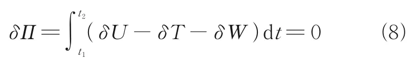
whereδU,δTandδWrepresent the variation in strain energy, kinetic energy and virtual work, respectively, which can be expressed individually as

(1) Strain energy variation
The strain energy variation of thebth blade could be expressed as
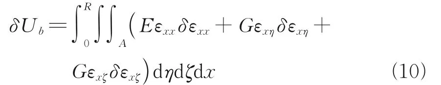
The moderate deformation of the blade caused the nonlinearity of the strain, which can be expressed as
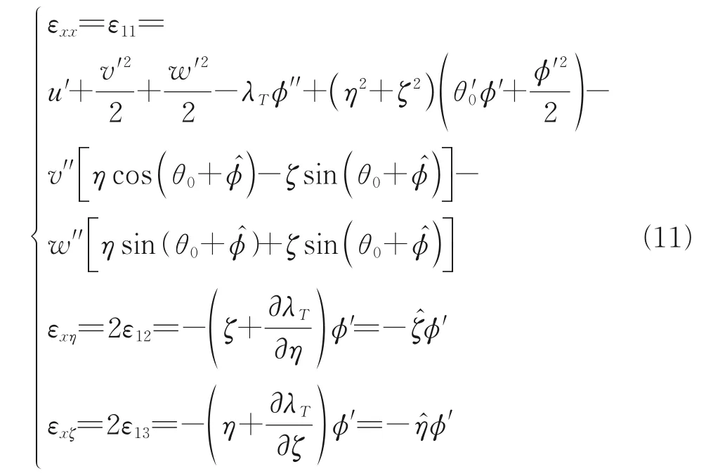
whereλTrepresents the warping function. The strain energy term is dimensionless and the order is preserved.
(2) Kinetic energy variation
The kinetic energy variation of thebth blade can be expressed as

(3) Virtual work variation
The virtual work variation of thebth blade can be expressed as

2.2 Bearing-less rotor system
The flexible beam and twist tube are described by the same form of finite elements[29]. The energy variation of the flexible beam blade system can be expressed as

The energy equation expression of thebth blade is

According to the arbitrariness of the virtual displacement theory, the nonlinear motion equation can be expressed as

whereMbis the mass matrix,Cbthe damping matrix,Kbthe stiffness matrix, andFbthe load vector of thebth blade[30].
2.3 Validation of rotor system
The natural frequencies of the flexible beam are calculated using the structural dynamics analysis model and ANSYS software, as shown in Table 2. As can be seen in Table 2, the calculation results are very close to those of ANSYS simulation, indicating that the dynamical model has high accuracy.

Table 2 Comparison of natural frequencies obtained by theory calculation and ANSYS calculation Hz
3 Two-Stage Optimization Model
3.1 Genetic algorithm
GA is used widely in optimization. A flow chart of the calculation process of GA is shown in Fig.6.

Fig.6 Flow chart of GA
The flexible beam structure dynamic optimization problem can be decomposed into two stages: Dynamic optimization and section optimization.
The energy equation and nonlinear motion equation of the blade are derived based on the Hamilton variational principle. The dynamic model of flexible beam-blade system structure is established and verified through an example. The influence of the length of the flexible section on the overall system dynamic characteristics is studied based on the blade data, and the selection range of the length of the flexible beam with the model blade is obtained.
The two-stage optimization process is shown in Fig.7.
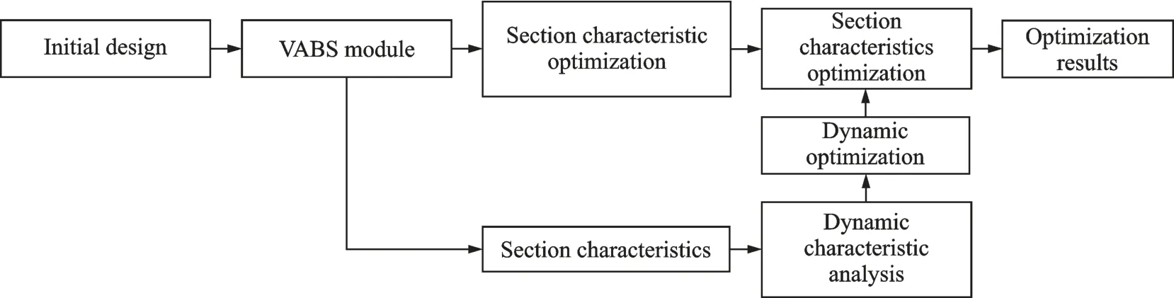
Fig.7 Flow chart of the two-stage optimization method
3.2 Structural dynamics optimization
The optimization model of the bearing-less rotor dynamic can be expressed as
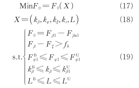
whereF0is the objective function;Xthe optimization variable set, including the stiffnesskand the length of the flexible beamL;β,φ,ξrepresent the motion in three directions: flapping, lead-lagging and torsion;Frepresents the natural frequency, in which the subscripts B and U represent the lower and upper boundaries; andfbrepresents the interval of lead-lag-torsion frequencies[26].
(1) Optimization target
The first-order natural frequency ratio of hingeless and bearing-less rotors is 1.08Ω—1.15Ω. The ratio of the expected frequency to the actual first-order flapping natural frequency shall be close to the required value and can be expressed as Eq.(17).
(2) Optimization variables
The first-order natural frequency ratio of hingeless and bearing-less rotors is 1.08Ω—1.15Ω. The ratio of the expected frequency to the actual first-order flapping natural frequency shall be close to the required value and can be expressed as Eq.(18).
(3) Optimization constraints
The design variables of dynamic optimization include the length of the flexible beamLand the stiffness of the root of flexible beamk, which is composed of tension stiffnessks, torsional stiffnesskξ, flapping stiffnesskβand lead-lagging stiffnesskφ, as shown in Eq.(19).
3.3 Section optimization
3.3.1 Section optimization
The mathematical model of the bearing-less rotor section geometry optimization can be expressed as

(1) Optimization target
The aim of geometry section optimization is to reduce the section torsional stiffness of the flexible beam to accommodate the required degrees of freedom.
The torsional stiffness should be significantly lower than the flapping stiffness and lead-lagging stiffness. Similarly, in the extension direction of the flexible beam, the torsional stiffness of the torsional deformation part should also be at a minimum[31]. The target can be expressed as Eq.(20).
(2) Optimization variables
The design variables are the geometric parameters of the flexible beam section. In this paper, a rectangular section with a determined areaYis selected as shown in Eq.(21).
(3) Optimization constraints
The design variables are the geometric parameters of the flexible beam section. In this paper, a rectangular section with a determined areaYis selected as Eq.(22).
3.3.2 Lamination optimization
Similar to the geometry section optimization, the mathematical model of the lamination optimization can be expressed as

whereθ3irepresents the lamination angle of theith ply,nmthe number of intermediate plies, andnthe total number of laminations.
(1) Optimization target
The optimization target is the lamination angle (-90°≤θ3≤90°), which has a great influence on the section characteristics as Eq.(23).
(2) Optimization variables
The optimization variable of the lamination optimization was the lamination angle (-90°≤θ3≤90°), which had a great influence on the section characteristics as Eq.(24).
(3) Optimization constraints
The constraints of lamination optimization were similar to those of section optimization as Eq.(25).
4 Results
The results of this paper are presented in two parts: The processes of the optimization and the validation of the optimization results.
The first part includes the processes and details of the structural dynamic optimization, section optimization and lamination optimization.
The second part includes the strength analysis and dynamic analysis of the optimization results. Here, the optimization results obtained are demonstrated to be reliable and reasonable.
4.1 Structural dynamics optimization
The first-order frequencies of flapping and leadlagging are taken as optimization objectives, and the weight coefficient is taken as the evaluation function. The population size is 50 and the population generation is 30. The optimization processes are shown in Fig.8.

Fig.8 Process of structural dynamic optimization of flexible beam
As can be seen in Fig.8, the fitness and average distance converge quickly, indicating that the genetic algorithm has good performance.
Through the optimization process, length and torsional stiffness of the flexible beam are obtained to satisfy the frequency requirement and as constraints to guide the subsequent geometric optimization step. The dynamic optimization results are shown in Table 3.
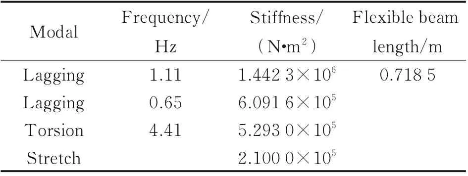
Table 3 Results of structural dynamic optimization with single objective
Through the structural dynamics optimization of bearingless rotor flexible beam, the length and torsional section stiffness are obtained and used as constraints to guide the subsequent optimization of the section parameters.
4.2 Section optimization
Based on the section characteristics obtained through the dynamic optimization, the geometric parameters of the flexible beam section are also optimized using the genetic algorithm. The optimization processes is shown in Fig.9.
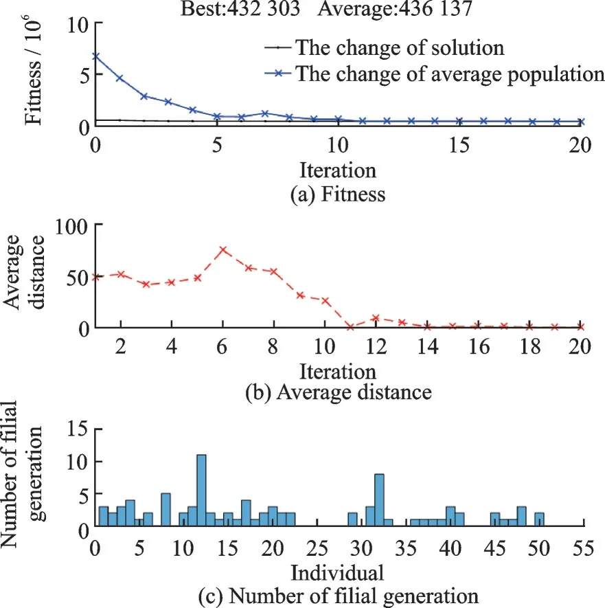
Fig.9 Process of section geometry optimization of flexible beam
As can be seen in Fig.9, the fitness and average distance converge quickly, indicating that the genetic algorithm has good performance.
The results of stiffness values and geometric parameters of optimization are shown in Table 4.
According to the results shown in Table 4, we can conclude that: Compared with the kinetic optimization, the torsion stiffness decreases by 18.1%;and compared with the equal area rectangular scheme (a=b), the torsion stiffness decreases by 41.7%. These results indicate that the section optimization under the constraint of leg-lagging stiffness has considerable effect on the optimization of torsional stiffness.

Table 4 Results of the section geometry optimization N·m2
4.3 Lamination optimization
The section optimization is carried out based on the geometric parameters of the flexible beam obtained through the geometric optimization. This paper presents two schemes of lamination optimization as shown in Fig.10 and Fig.11, respectively.
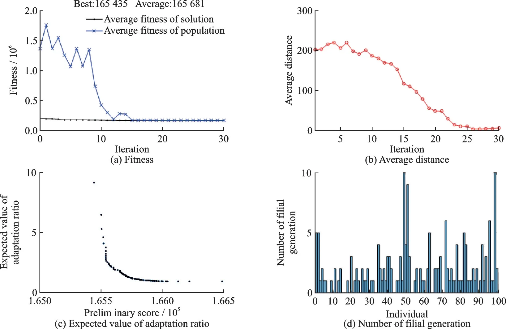
Fig.10 Process of section lamination optimization of flexible beam (Scheme 1)

Fig.11 Process of section lamination optimization of flexible beam (Scheme 2)
According to the results in Fig.10 and Fig.11, the fitness and average distance converge quickly, indicating that the genetic algorithm has good performance.
The optimization results of the two general lamination schemes are shown in Table 5.
Based on the data in Table 5, the lamination parameter scheme of flexible beam is obtained to reduce the torsional stiffness of the section. The results show that the torsional stiffness of Scheme 1 reduces by 66% compared with the full 0° layering scheme, whereas the torsional stiffness in Scheme 2 decreases by 36.1%. This indicates that the optimization scheme has a significant effect on reducing the torsional stiffness.
4.4 Strength analysis
A composite material flexible beam composed of 36 laminations is established. Fixed constraints and centrifugal force are applied at the root of the beam and the tip of the beam, respectively. The stress distribution of each lamination is obtained. The total deformation of the flexible beam under centrifugal force is 22.18 mm. The stress distributions of the dangerous lamination are shown in Table 6. According to the results in Table 6, the safety factor of each dangerous stress lamination is less than 1, which indicates that the composite material flexible beam does not fail under the centrifugal force load of the blade.
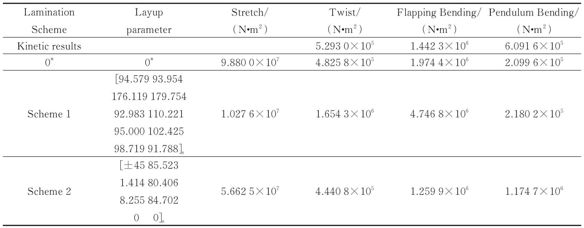
Table 5 Optimization results of section lamination

Table 6 Checklist for dangerous stress lamination of flexible beams
4.5 Dynamic analysis of flexible beam
The modal analysis of the flexible beam blade model is carried out to analyze its dynamic characteristics. During the rotation of the rotor, the effect of the pre-stress generated by the centrifugal force will affect its natural frequency. Therefore, to analyze the dynamic characteristics of the rotor’s flexible beam and the blade in its working condition, it is necessary to validate it under working speed.
The first 6-order frequencies are shown in Table 7.

Table 7 The first 6-order frequencies of the flexible beam blade at the working speed
Figs.12—14 show the first one order of torsion, first two orders of lead-lagging, and first three orders of flapping of resonance diagrams. According to the results shown in Figs.12—14, the natural frequencies of flapping and torsion meet the requirements: The flexible beam is 0.5Ωaway from the passing frequencies of the blade, 0.25Ωaway from the excitation force frequency, and the natural frequencies of flapping and torsion keep a corresponding distance. These results indicate that the dynamic characteristics meet the design requirements.

Fig.13 Lagging resonance diagram of flexible beam

Fig.14 Feathering resonance diagram of flexible beam
It is worth noting that the first-order natural frequency of torsion at the working speed in Fig.12 is close to the exciting force caused by 3Ω. This is mainly because the natural frequency of torsion is also associated with the stiffness of the control wire system. Therefore, the design of the torsional dynamic characteristics should also consider the design of the control system.
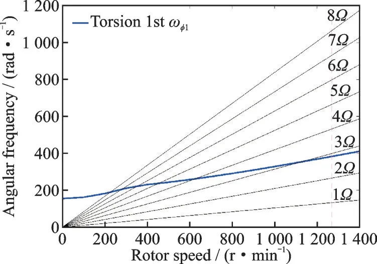
Fig.12 Flapping resonance diagram of flexible beam
5 Conclusions
VABS program is used to calculate the section characteristics, and the mass and stiffness characteristics of the section are also obtained. A dynamic analysis method of the isolated blade is established based on the Hamilton variation principle and the moderately deformation beam theory.
A two-stages optimization method of flexible beam is established. Its results show that the torsional stiffness of the design section of the flexible beam is significantly reduced. The dangerous stress laminations of composite flexible beams are in safe range. The dynamic characteristics of the flexible beam blade system are obtained at the working speed, and the resonance diagram is drawn in the design speed range. The results show that the design scheme meets the design requirements.
The optimization results show that the torsional stiffness decreases by 36.1% compared with the full 0° laying scheme without optimization and the dynamic requirements are achieved. The natural frequencies of flapping and torsion meet the requirements (0.5 away from the passing frequencies of the blade, 0.25 away from the excitation force frequency, and the flapping and torsion frequencies keep a corresponding distance). The results indicate that the optimization method can significantly improve the performance of the flexible beam.
Further research of the following characteristics is recommended: (1) The torsional frequency of the bearing-less rotor is also associated with the structural characteristics of the twisted tube part and therefore, a dynamic optimization design research including the twisted tube will yield more accurate results. (2) The dynamic optimization design of flexible beam structure is only developed based on the rectangular section, but real engineering design would require more complex sections.
Traditional optimization methods of flexible beam design could only optimize either the geometric or the dynamic characteristic. This paper establishes a two-stage optimization method based on genetic algorithm that can optimize both section and dynamic characteristics, significantly improving the performance of the flexible beam. The method and modals proposed could be potentially used to guide the design and optimization of the flexible beam in other bearing-less helicopter rotor systems.
杂志排行
Transactions of Nanjing University of Aeronautics and Astronautics的其它文章
- Analysis of Magnetic Positioning for Liquid Oxygen Under Microgravity Condition
- Mechanical Analysis and Numerical Simulation for New Type of Dynamic Control Devices
- Aircraft Optimal Separation Allocation Based on Global Optimization Algorithm
- Adaptive Tracking Control for Diffractive Film Based on Nonlinear Sliding Mode
- Iterative Identification of Robot Dynamic Parameters Based on Logistic Function
- Path Planning for Lunar Surface Robots Based on Improved Ant Colony Algorithm