A Model-Based Unmatched Disturbance Rejection Control Approach for Speed Regulation of a Converter-Driven DC Motor Using Output-Feedback
2022-01-25LuZhangJunYangandShihuaLi
Lu Zhang,Jun Yang,,and Shihua Li,
Abstract—The speed regulation problem with only speed measurement is investigated in this paper for a permanent magnet direct current (DC) motor driven by a buck converter.By lumping all unknown matched/unmatched disturbances and uncertainties together,the traditional active disturbance rejection control (ADRC) approach provides an intuitive solution for the problem under consideration.However,for such a higher-order disturbed system,the increase of poles for the extended state observer (ESO) therein will lead to drastically growth of observer gains,which causes severe noise amplification.This paper aims to propose a new model-based disturbance rejection controller for the converter-driven DC motor system using output-feedback.Instead of estimating lumped disturbances directly,a new observer is constructed to estimate the desired steady state of control signal as well as errors between the real states and their desired steady-state responses.Thereafter,a controller with only speed measurement is proposed by utilizing the estimates.The performance of the proposed method is tested through experiments on dSPACE.It is further shown via numerical calculations and experimental results that the poles of the observer within the proposed control approach can be largely increased without significantly increasing magnitude of the observer gains.
I.INTRODUCTION
DIRECT current (DC) motors are applied extensively in industry,particularly in the systems requiring higherprecision,such as the automotive industry [1],elevator systems [2],robotic manipulators [3],etc.In the early days,the configuration of DC motor drives consists of a resistance network connected in parallel/series with DC motor,but due to the non-smooth regulation,it causes abrupt jerkiness and changes.Recently,DC-DC converters are used to act as smooth starters for DC motors [4],which provides a solution for the aforementioned problem.However,the converterdriven DC motor system usually faces various disturbances/uncertainties,which are briefly summarized as follows:1) unknown constant or time-varying load torques[5];2) unknown parametric uncertainties such as the external source voltage [6],the load resistor,the winding resistor [7],etc.;and 3) unmodeled dynamics such as the equivalent series resistance in converter systems and measurement error [8].Due to the aforementioned challenges,researchers propose various control strategies to solve the angular velocity regulation problem therein,such as proportional-integral (PI)control [9],backstepping control [10],flatness-based tracking control [11],sliding mode control [12],robust control [13],ADRC [14],etc.
In light of appealing properties including conceptual simplicity and powerful disturbance rejection performance,the active disturbance rejection control (ADRC) method[14]–[16] has gained a lot of attention in the area of speed regulation of buck converter-driven DC motors [14],[17].An observer-based control strategy is proposed in [18] for a permanent magnet motor to reject harmonic torque disturbances,which combines observation with the linear PI controller.In [19],a triple-step controller is proposed to solve the speed regulation problem for a permanent-magnet DC motor subject to uncertainties and disturbances.Furthermore,the authors of [20] propose an observer-based nonlinear triplestep controller to improve the low-speed tracking performance for permanent-magnet DC motor systems.Both the two controller proposed by [19] and [20] utilize a reduced-order mathematical model,which neglects the electrical time constant of the DC motor.In [21],a flatness tracking controller is proposed by using the simple second-order model,but this method would decrease the system bandwidth.In [13] and [22],based on a full fourth-order dynamic model,the ADRC method is applied to address the speed regulation problem for the converter-driven DC motor system.Since the overall system is fourth-order,in the framework of traditional ADRC,it is required to perform fourth-order differentiations to obtain the so-called standard control form,the design procedure of which is clearly shown in [13] and [22].
For the system under consideration,performing fourth-order differentiations and lumping system dynamics as a part of the unknown input term will lose system dynamic models.It is generally required to assign a conservatively higher observer bandwidth in traditional ADRC to achieve higher estimation and control precision as the lumped uncertainties usually have an unknown complicated structure.However,for such a fourth-order system,the increase of observer bandwidth means large poles,which will lead to a drastic rise of the amplitude of observer gains,causing significant amplification of measurement noises.On the other hand,the derivatives of the desired angular velocity may be unavailable in certain applications such as position control.The traditional ADRC solves this problem by adding tracking differentiators to estimate the unknown information,which considerably increases the complexity in implementation.In [23],a generalized extended state observer (ESO)-based control strategy is proposed for unmatched disturbance compensation in the framework of ADRC,where a static disturbance compensation gain is designed for compensation.It is claimed that the method in [23] can tackle the output-feedback control problem.However,it only provides partial output-feedback control since it usually needs more measurements to satisfy the observability conditions therein.In addition,the number of the extended states is equal to the number of disturbances to be estimated,which leads to a higher dimension of the observer [23].As such,it is imperative to investigate new control strategies for the DC-DC buck converter-driven DC motor system to solve these problems as well as ensure satisfactory control performance and disturbance rejection capability.
Motivated by the traditional ADRC and the output regulation theory [24],[25],this paper proposes a new disturbance rejection control approach for the buck converterdriven DC motor system to improve the control performance in the presence of various parametric uncertainties and unknown load torque disturbances.The benefits as well as differences from existing works of the proposed method are summarized as follows:
1) Delicate Analysis of the Benefits of the Proposed Controller:The explicit relationship between the observer gains and the assigned poles has been developed for both the proposed method and the ADRC method.The results show that the observer gains under the proposed observer are much lower than the traditional ADRC method provided that they have the same observer poles.The fundamental difference lies in that the nominal system dynamics are fully exploited in the proposed observer design.This important feature allows for better performance balance between noise attenuation and disturbance rejection of the proposed method.
2) Comparison With Existing Related Approaches:Since this paper is concerned with unmatched disturbance rejections via output-feedback control,it is worthy to note that most of the existing results focus on state-feedback control design[26]–[28] except for the active disturbance rejection control(ADRC).The potential difficulty for designing an outputfeedback disturbance rejection controller is that it is quite challenging to estimate both the unknown states and unmatched disturbances simultaneously.Consequently,we provide a thorough comparison with the traditional ADRC approach,which is a well-known output-feedback disturbance rejection controller,from different aspects including with a methodological perspective,delicate theoretical analysis and experimental comparisons.
It should be mentioned that the preliminary version of the paper has been published in [29],where a very basic control design is considered for the buck-converter driven DC motor system subject to only load torque disturbance.The result therein is far from complete due to the following three reasons:1) The parameter uncertainties are not considered therein,which are inevitable for the system under consideration;2) The result is not complete theoretically since no rigorous performance analysis have been presented in that paper to show the relationship between the ultimate bounds and the observer parameters;3) There lacks a thorough theoretical analysis and experimental results to show that the proposed approach exhibits advantages over the traditional control approaches.Compared with [29],this paper enriches the results in both theory and experiment aspects.
II.PRELIMINARIES AND MOTIVATIONS
A.Model of Converter-Driven DC Motor System
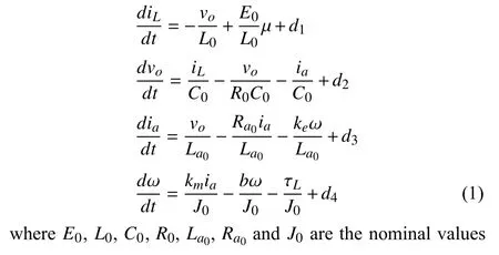
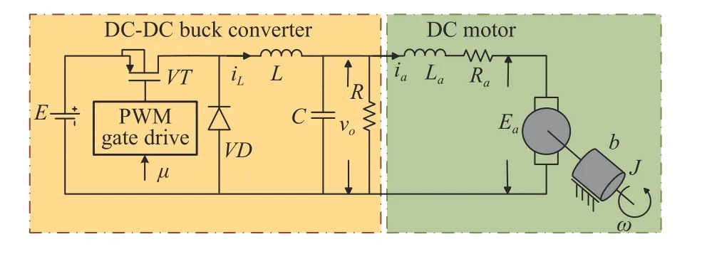
Fig.1.Circuit of the buck converter-driven DC motor system.
The basic circuit of the buck converter-driven DC motor system considered in this paper is shown in Fig.1.In the buck converter circuit,there is a DC input voltageE,a switchVT,a diodeVD,a pulse width modulation (PWM) gate drive,a load resistorR,a capacitorCand an inductorL.The DC motor consists of an induced electromotive forceEa,an rotor winding resistorRaand an armature inductorLa.The nominal moment of the rotor inertia is denoted asJ.Based on Kirchhoff’s law,the system dynamic model is given by ofE,L,C,R,La,RaandJ,respectively.The first two formulas of (1) correspond to the dynamics of the buck converter,in whichiLandvoare the inductor current and capacitor voltage of converter,respectively,µ∈[0,1] is the duty ratio.The last two formulas represent the dynamics of the DC motor,in whichiaandωdenote the armature current and angular velocity of the motor,respectively,kmis motor torque constantkeis counter electromotive force constant,bdenotes the motor viscous friction coefficient,τLis the unknown time-varying load torque.Moreover,d1,d2,d3andd4are lumped disturbances denoted by
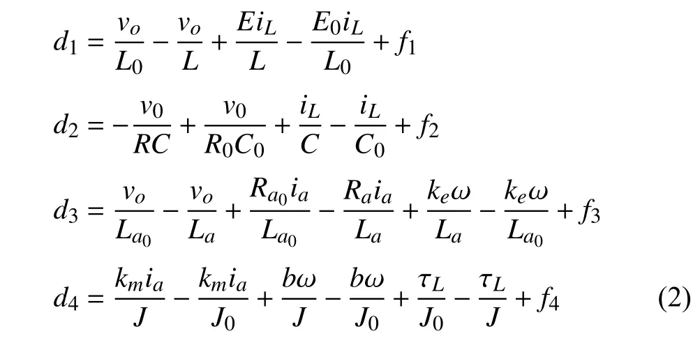
wherefi,i=1,2,3,4 represents the rest unmodeled uncertainties in each channel.
Remark 1:The unmodeled uncertainties in the converterdriven DC motor systems include the cogging torque,highorder back-electromotive force (EMF) harmonics,dead-time effects,etc.According to the existing results,the cogging torqueTcogis modeled in detail in [30] aswhere θm=θe/npis the mechanical angular position of the rotor,Qis the number of the slots,andTcogiand φiare the corresponding amplitude and phase angle.It is very difficult to model all the unmodeled uncertainties in detail,thus,we treat the unmodeled uncertainties as part of disturbances in this paper.Under the control framework proposed in this paper,the effects of disturbances can be estimated and compensated for in the controller.As a result,the effects from unmodeled uncertainties can be eliminated in the control performance.
B.Research Motivation and Control Objective
As mentioned in the introduction of the paper,the traditional ADRC and the generalized ESO-based control approach in [23] provide possible solutions for the problem under consideration.The potential limitations of these two approaches are elaborated in this subsection.
1) Traditional ADRC:Generally,the traditional ADRC method for system (1) under consideration is designed based on the fourth-order integral chain system [22],where the observer is designed as

whereκis a constant that depends on the circuit parameters,and ω∗is the desired angular velocity.li,i=1,2,3,4,5 is the observer gain to design.ν1=ω−ω∗,,i=1,2,3,4,5 denote estimations ofand the lumped disturbance,respectively.The ADRC law is designed as

where φi,i=1,2,3,4 is the controller gain to be designed.It is assumed that the observer poles are set as −ωo(ωo>0),and the observer gains in (3) are obtained and given by

The traditional ADRC method can remove the offset caused by unmatched disturbances asymptotically but through the integral-chain coordinate transformation shown in [22],where system dynamics have not been fully exploited.For the fifthorder observer in (3),the observer gain shows polynomial growth in terms of the increase of the poles for the observer.It is natural that large observer gains will seriously amplify measurement noises and thereby cause abrupt changes in estimates as well as the control signal.
2) Generalized ESO-Based Control:In [23],a generalized ESO-based control strategy is proposed for unmatched disturbance compensation.The design procedure is revisited as follows.
Letx=[iL,vo,ia,ω]T.The compact form of the converterdriven DC motor system (1) is given by

whereA,b,bdandCare matrices with compatible dimensions,andd=[d1,d2,d3,d4]T.Denotex¯=[iL,vo,ia,ω,d1]T.The generalized ESO is designed as
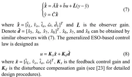
Following the guidelines given in [23],for the given converter-driven DC motor system (1),it is verified that the observability condition is not satisfied for the designed observer in (7) and thus the generalized ESO-based control approach is not available for the present control problem.
Control Objective:This paper aims to design a new outputfeedback speed regulation controller for the converter-driven DC motor system (1) subject to various matched/unmatched uncertainties and disturbances.The controller can fully exploit the nominal model of the system given in (1) and only requires the output measurement.Under the proposed controller,the angular velocityωof the DC motor tracks the desired signal ω∗asymptotically even in the presence of unmatched disturbances.
III.MAIN RESULTS
A.Controller Design
By utilizing the basic principle of output regulation theory[24],the steady states of the buck converter-driven DC motor system can be calculated by solving the following regulator equations:
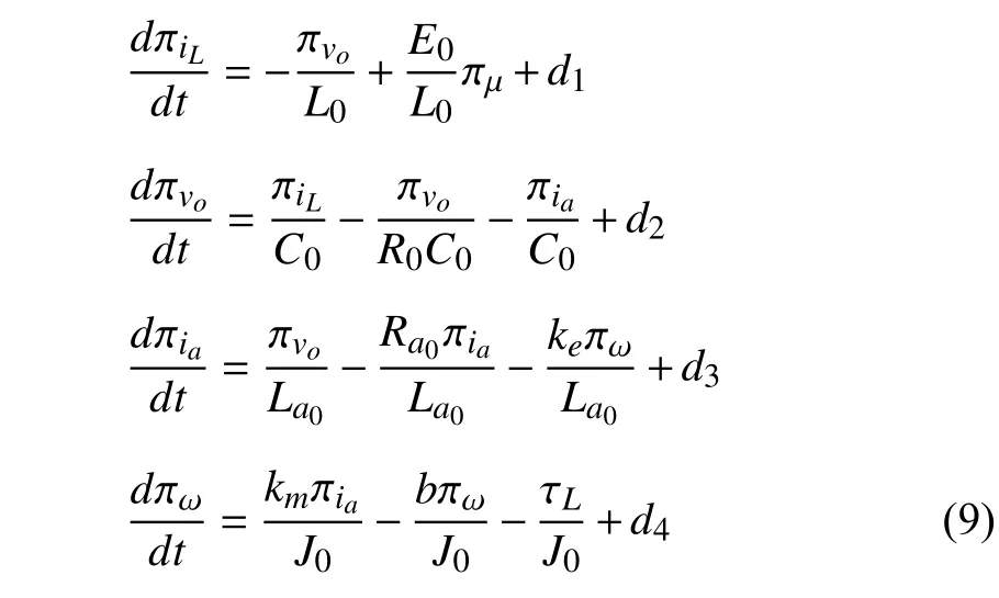
where πiL,πvo,πia,πωand πµrepresent the desired steadystate responses ofiL,vo,ia,ωandμ,respectively.
Remark 2:As per the output regulation principle [24],here the actual dynamic system (1) will be driven to its steady-state manifold governed by (9).It is clear that the steady-state manifold is naturally determined by the actual disturbances.This is the reason why the actual disturbances (2) appear in both the actual system (1) and the regulator equations (9).
Define the following coordinate transformation:

Taking the time-derivatives of (10) along (1) and (9),one obtains

Since πµis a function with respect to disturbances,we denote πµas an extended state.Then the augmented system is given by
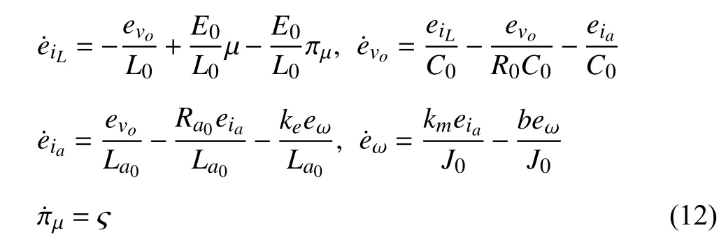
where ς=dπµ/dt.The output of system (12) is the measurableeω.
To begin with the observer design,we denote the state estimations in (12) asAn observer for system (12) is then designed as follows:

where
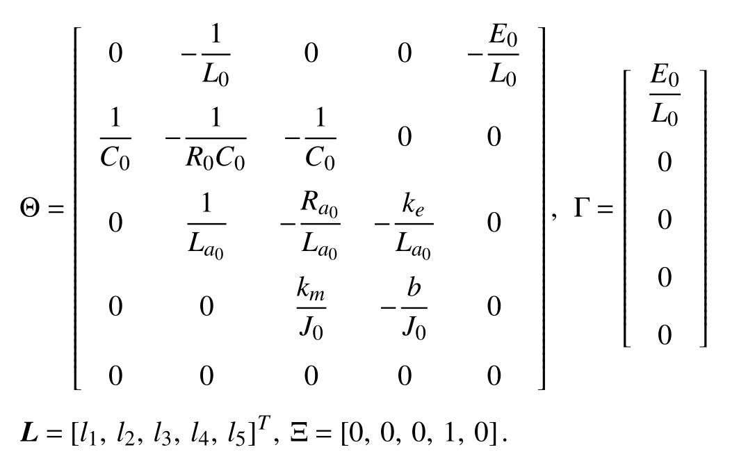
Remark 3:Since both the states and their steady-state responses are unknown,it is generally quite difficult,if not impossible,to estimate the unknown states and their desired steady-state responses simultaneously.Consequently,we propose a new manner to estimate error signals between the unknown system states and their desired steady-state responses directly by using adequate coordinate transformations.By virtue of coordinate transformations,an observer shown in (13) is proposed to identify the estimated parameters in the paper.
By virtue of the estimations generated in (13),the composite controller is designed as follows:

Remark 4:The controller can also be designed as

sinceeωis available.In practice,if the sensor noises are severe and unacceptable,it is advised to choose the controller given in (14) since the observer can be taken as a low-pass filter as well [31].
Remark 5:The solutions of the regulator equations (9) are not needed in implementation.From the coordinate transformation given in (10),the augmented system (12),the observer,and controller given by (13) and (14),it is known that although we cannot calculate,anddue to the presence of unknown disturbances,the controller can be implemented based on the observation technique.
B.Performance Analysis
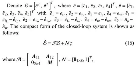
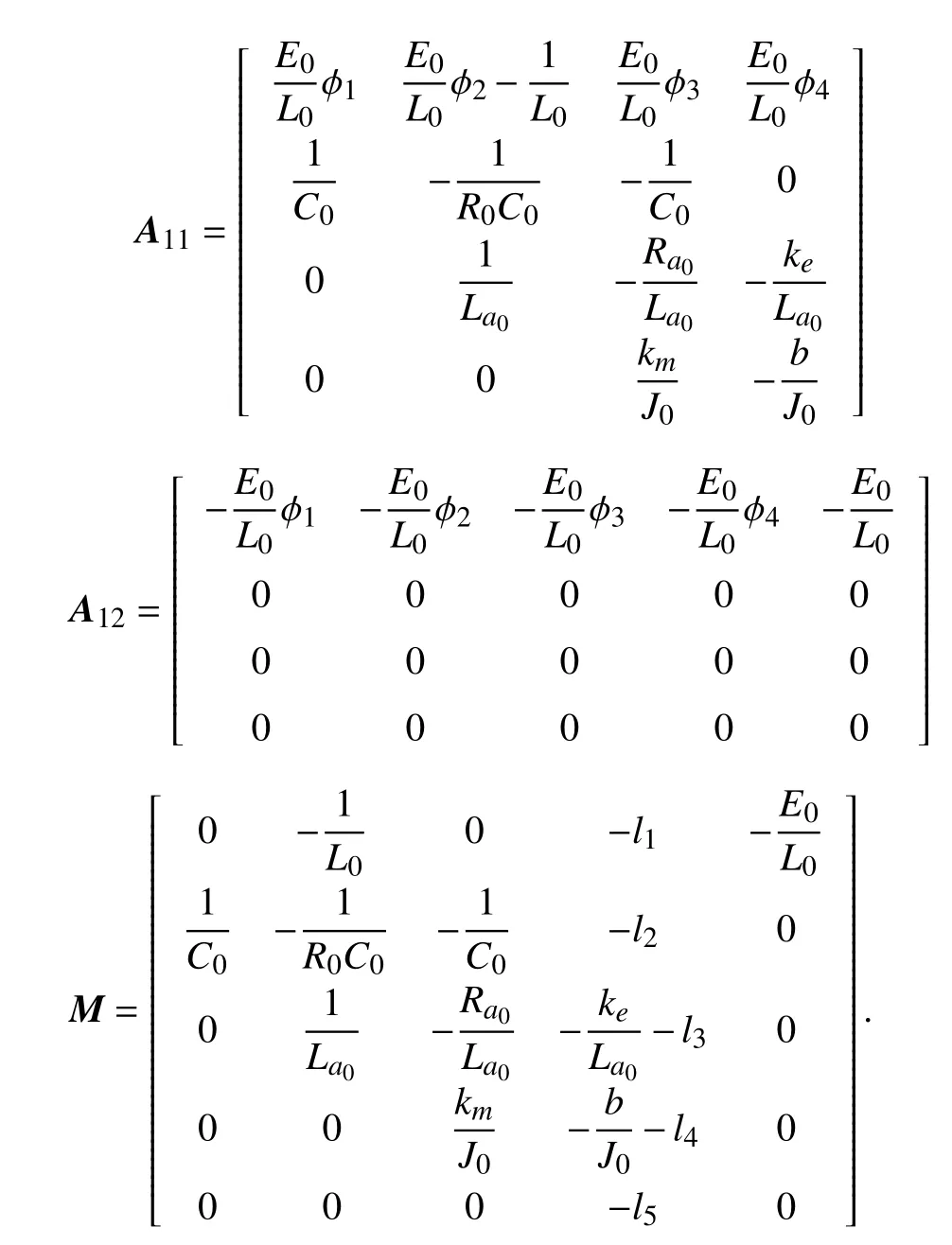
The stability of the closed-loop buck converter-driven DC motor system is established by the following theorem.
Theorem 1:For a bounded ς,if the observer gainLin (13)and the feedback control gain Φ in (14) are chosen such thatMandA11are Hurwitz,respectively.Then,both the estimation errors and the angular velocity tracking error will converge to a bounded neighborhood of the origin and the ultimate bounds can be assigned arbitrarily small by adjusting the poles of the observer.
Proof:The proof of the theorem is divided into the following three steps.
Step 1:By the definition of input-to-state stability (ISS)[32],there exist a class of KL function β1and a class of Kfunction β2such that for any bounded ς(t) and initial state E(0),the solution E(t) of system (16) satisfies‖E(t)‖≤β1(‖E(0),t‖)+β2(sup0≤τ≤t|ς(τ)|).Moreover,ast→∞,there is‖E(∞)‖≤β2(δ)<∞ with |ς(t)|≤δ,whereδis a positive constant.Therefore,the speed tracking error and the estimation errors are all bounded.
Step 2:We assign the eigenvalues ofMandA11as−ωo(ωo>0) and −ωc(ωc>0).The observer error dynamics are evaluated first,whose formation is depicted by
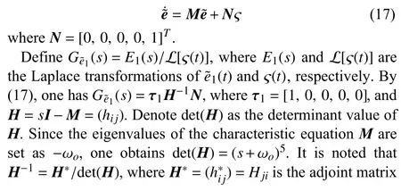

To proceed with the analysis,we present the following statement:For a system
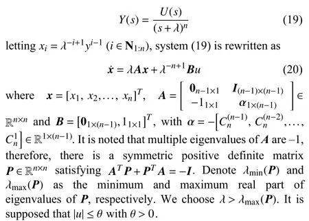
A Lyapunov function is constructed asV(x)=xT Px.The first-order derivative ofV(x) is obtained as
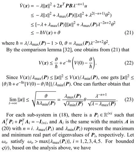
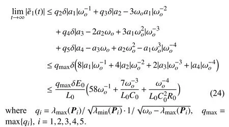
Through similar analysis,we get the other four estimation errors as follows:
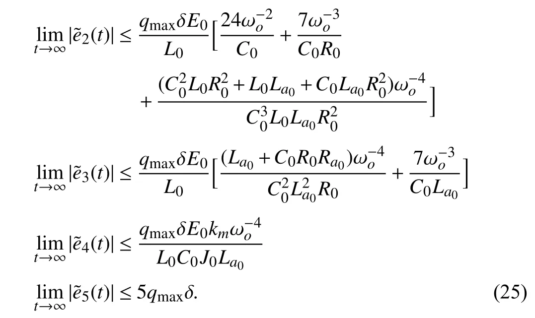
It is obvious that the ultimate bound of(i=1,2,...,5) can be arbitrarily small by magnifying ωo.
Step 3:The tracking error subsystem is written as
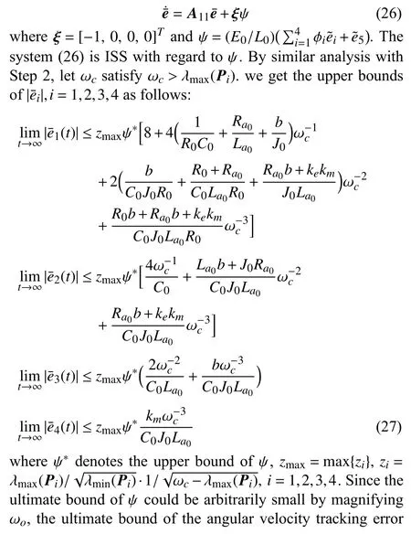

Next,the disturbance rejection ability of the closed-loop system under controller (14) is summarized as follows.
Theorem 2:If ς(t) tends to zero as t tends to infinity,the observer gainLin (13) and the controller gain Φ in (14) are chosen such thatMandA11are Hurwitz,andis invertible withC=[0,0,0,1],then the angular velocity ω in(1) tracks the desired value ω∗asymptotically in the presence of disturbances/uncertainties under the control law (14).
Proof:From (17),under the given condition and Theorem 1,we have

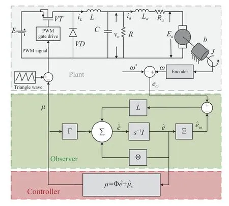
Fig.2.Control structure of the model-based output-feedback controller.
IV.ExPERIMENTAL VERIFICATIONS
To validate the performance of the proposed model-based control strategy,experiments on a buck converter-driven DC motor system are carried out in this section.
A.Experimental Test Setup
As shown in Fig.3,the experimental test setup contains a buck converter,a permanent magnet DC motor (DBM100),a tension controller,a magnetic powder brake device for regulating load torque,an incremental photoelectric encoder(A and B two-phase output,resolution of 1 000 lines),a programmable DC power source (EA-PSI9500-20 2U),and dSPACE DS1103 real-time controller.For experimental studies,the sampling frequency and the controller updating frequency is setting as 3.3 kHz.The fixed PWM switching frequency of the converter is 10 kHz.The algorithm is implemented by dSPACE DS1103 control board,which can achieve seamless connection with MATLAB/Simulink.Table I shows nominal values of parameters for the buck converterdriven DC motor circuit.
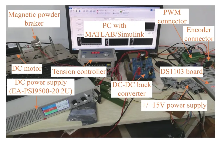
Fig.3.Experimental prototype.
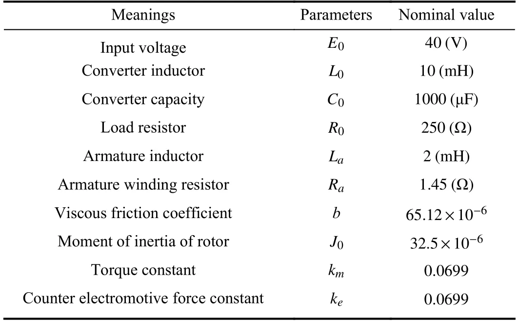
TABLE IPARAMETERS OF BUCK CONVERTER-DRIVEN DC MOTOR SYSTEM
B.Experimental Results and Analysis
To demonstrate the efficiency of the proposed controller,the traditional ADRC method and the proportional integral derivative (PID) controller are employed for comparison for experimental studies.The traditional ADRC method is designed along (3) and (4).The PID controller is designed as

Parameter tuning of different controller is definitely significant in providing fair performance comparisons.It is well known that,there are usually a number of conflicts/constraints in control design and parameter tuning,such as tracking versus disturbance rejection and nominal performance versus robustness.As such,it is generally impossible to design and tune a controller with all performances better than others.For fair comparison,one sensible option is to tune the controllers so that obtain similar performance specifications and then compare the others.Since this paper focuses on disturbance/uncertainties attenuation,for fair performance comparisons among the three controllers,the control parameters of each controller are tuned such that the speed tracking profiles have similar performance specifications,such as settling time and overshoot,in the absence of disturbances and uncertainties.Subsequently,the robustness and disturbance rejection performances are fairly compared.
For traditional ADRC design,the feedback control and observer parameters are tuned by using pole placement approached [33].The PID controller is tuned by trail and error approach such that one can get satisfactory tracking control performance.To conclude,we aim to assign adequate control parameters of traditional ADRC and PID approaches such that one can obtain desirable static and dynamic speed reference tracking performance,such as short settling time and small overshoot.
The controller poles of the proposed method and the ADRC are set as the same.In the experiment,the observer poles of the proposed method are chosen as–500,and the observer poles of the ADRC method are chosen as–300.(The reason why we choose different poles for the two observers will be discussed in the next section.) The parameters of the three controllers are shown in Table II.In this section,we present four cases of disturbances and uncertainties,where the detailed experimental scenarios are listed in Table III.
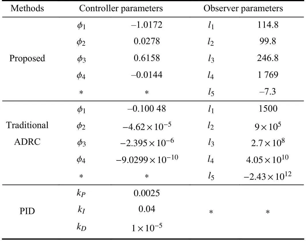
TABLE IICONTROL PARAMETERS OF THREE CONTROL APPROACHES
Case I– Time-Varying Reference Speed Tracking:In this case,the reference speed is expressed asω∗=80+75sin(2πt)rad/s.For all three controllers,the higher-order timederivations of the reference signal are not utilized.The tracking response curves and duty ratio profiles are shown in Fig.4,which shows that,with similar level of duty ratios,the proposed control approach has much smaller speed tracking error as compared with the traditional ADRC and PID control approaches.
Case II– Sudden Input Voltage Changes:The input voltage changes from 40 V to 30 V at 1.3 s and recovers to 40 V at 3.3 s.Fig.5 shows the response curves in this case.

TABLE IIIExPERIMENTAL SETUP SCENARIOS
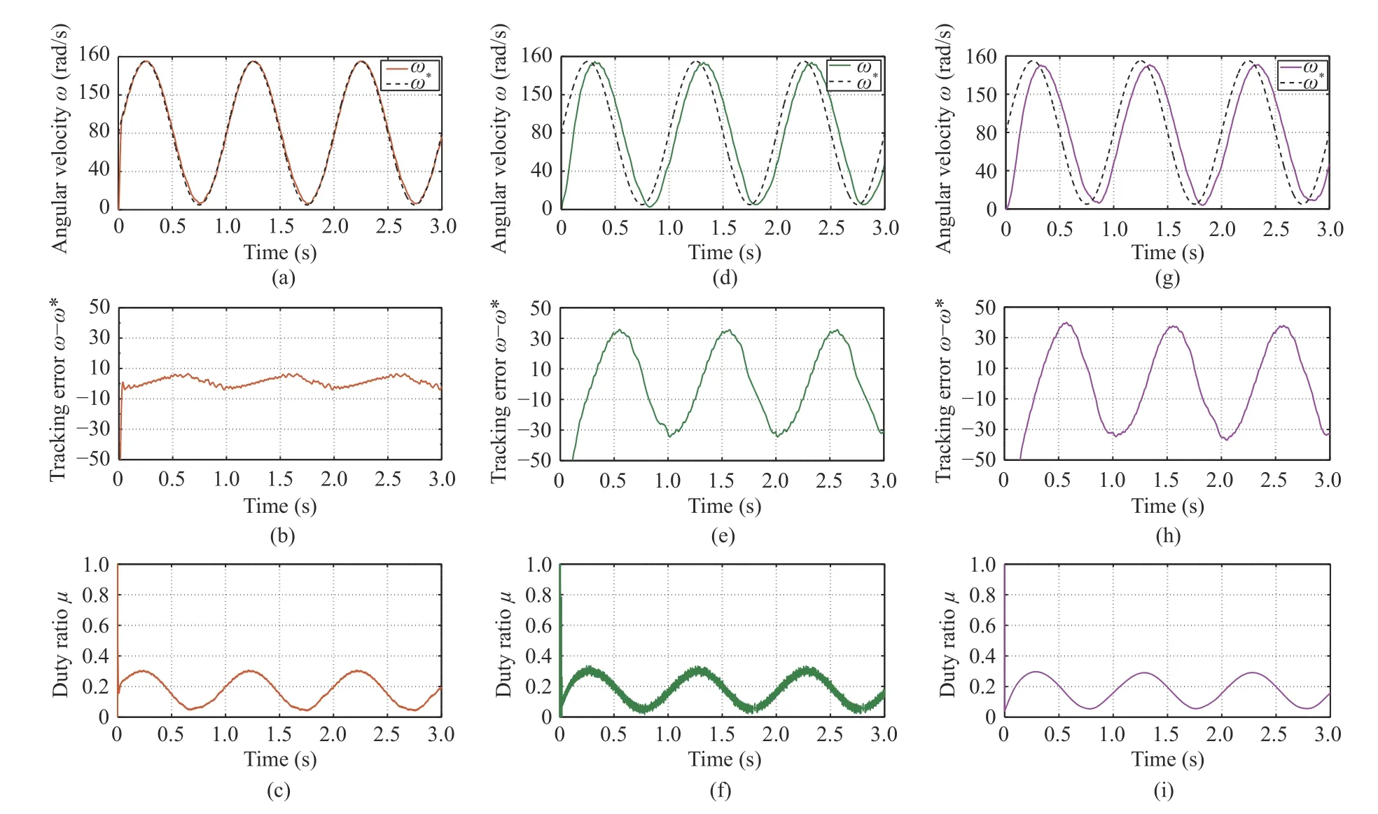
Fig.4.Response curves under the proposed method (left),traditional ADRC (middle) and PID (right) for time-varying reference speed tracking (Case I) (top:angular velocity;middle:tracking error;bottom:duty ratio).
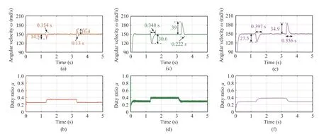
Fig.5.Response curves under the proposed method (left),traditional ADRC (middle) and PID (right) with sudden input voltage change (Case II) (top:angular velocity;bottom:duty ratio).
Case III– Sudden Load Torque Disturbance:When sudden load torques are imposed,the experimental results are shown in Fig.6.It can be seen from Fig.6 that the proposed control approach has obtained much better transient regulation performance than the other two control approaches.
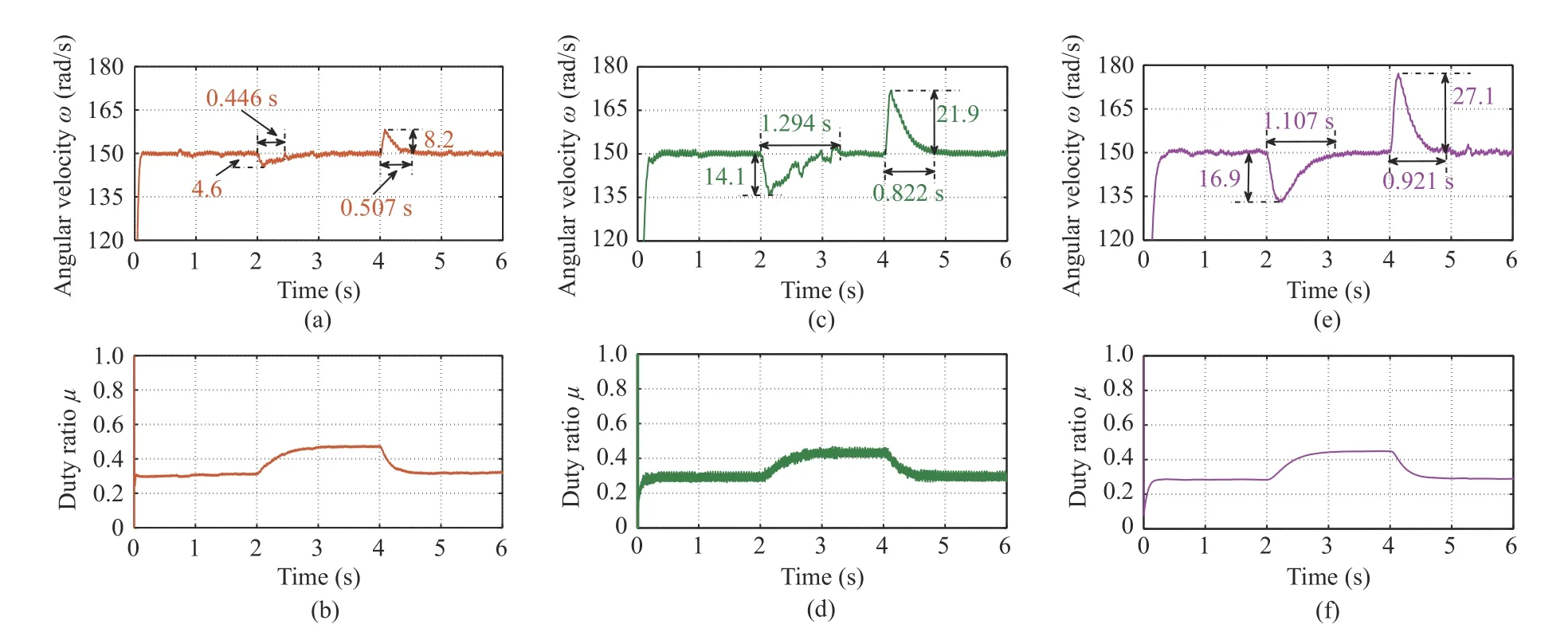
Fig.6.Response curves under the proposed method (left),traditional ADRC (middle) and PID (right) with sudden load torque disturbance (Case III) (top:angular velocity;bottom:duty ratio).
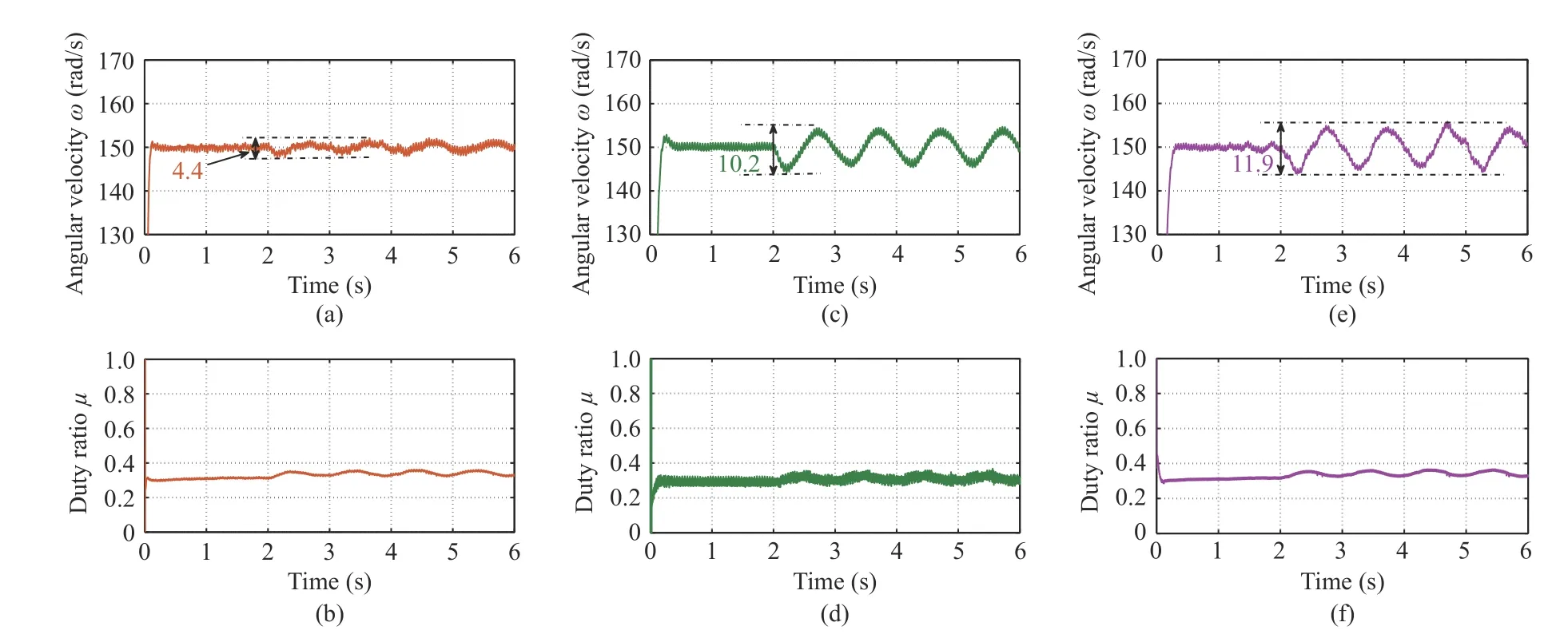
Fig.7.Response curves under the proposed method (left),traditional ADRC (middle) and PID (right) with time-varying load torque disturbance (Case IV)(top:angular velocity;bottom:duty ratio).
Case IV– Time-Varying Load Torque Disturbance:Different from Cases II and III where constant disturbances are considered,in this case,we aim to evaluate the influences of persistent time-varying external disturbances on the steadystate performance.Response curves of the system output and control signal are shown in Fig.7,from which it can be seen that the proposed control method achieves much smaller steady-state speed fluctuations than the traditional ADRC and PID control schemes.
In order to compare control performance under different controllers in more detail,we evaluate the performance specification quantitatively.The performance indices including maximum angular velocity drop/raise(MAVD/MAVR) and maximum recovery time (MRT) are utilized for performance validation.The corresponding speed regulation performance indices are summarized in Table IV.
Remark 6:It is observed from Fig.5 the control performance of ADRC is better than PID controller,but in Fig.6,the control performance of ADRC is worse than that of the PID controller.The reason is that Figs.5 and 6 show experimental results in the presence of sudden input voltage changes and sudden load torque disturbances,respectively,and different disturbances from different channels may have different effects on the control performance.We can actually obtain better control performance by choosing larger poles for ADRC,but larger poles will seriously amplify measurement noises and thereby cause abrupt changes of the estimates as well as the control signal.

TABLE IVREGULATION PERFORMANCE INDICES IN THREE CASES
Remark 7:It should be pointed out that there exists a difference between the theoretical analysis of (24) and (25)and the experimental results given in the following section,since there are many factors such as noises and control authorities affecting the control performance in practice.
V.DISCUSSIONS
In this Section,we will pay particular attention to observer gains comparisons between the proposed method and the traditional ADRC method.The relationship between the observer poles (set as −ωo) and observer gains under the proposed model-based observer (13) are given as follows:
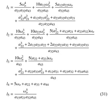
wherea12=−1/L0,a15=−E0/L0,a21=1/C0,a22=1/R0C0,a23=−1/C0,a32=1/La0,a33=−/,a34=−ke/,a43=km/J0,anda44=−b/J0.For the traditional ADRC method,the relationship is shown by (5).By substituting the model parameters of the converter-driven DC motor into (31)and (5),one can obtain the relationships between the observer gains and poles for both methods numerically,which are shown in Fig.8 and Table V.
As shown by Fig.8 and Table V,the observer gains of the traditional ADRC increase drastically as the poles of the observer increases.However,due to full utilization of the nominal model,when enlarge the poles of the observer,the observer gains of the proposed control approach increase much slower than the traditional ADRC approach.This provides great potential for measurement sensor noise attenuation,which will be elaborated on in the following experimental study.
We set the speed reference signal as ω∗=150 rad/s.Two different observer poles ωo=−500 and ωo=−300 are considered here for the traditional ADRC method,while other controller settings are the same as those in Section V for both ADRC and the proposed method.
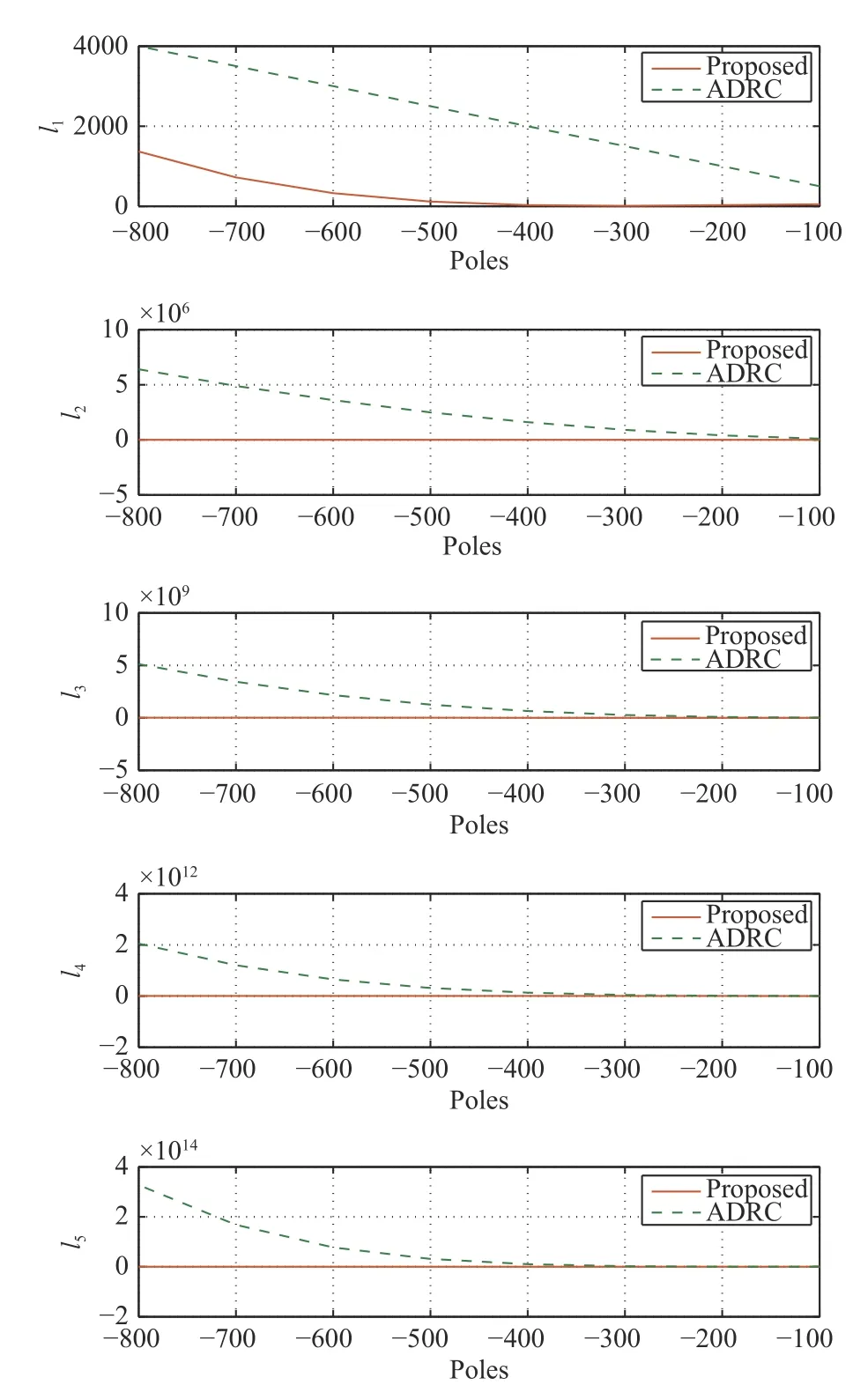
Fig.8.Relationship between observer gains and poles.
The response curves of the speed,the observer outputs and duty ratio are shown by Fig.9.It can be obtained from the comparison results that with larger observer poles,the traditional ADRC can obtain faster speed tracking performance but larger overshoot and considerable sensor noise amplification.In particular,it can be observed from Fig.9(f) that the duty ratio drastically fluctuates with a traditional ADRC with poles ωo=−500.This supports the previous statement that the proposed strategy has an excellent property where an increase the observer poles does not significantly amplify sensor noise.Therefore,the proposed controller widens the bandwidth without bringing any adverse effects.
Remark 8:For the experiments in last section,if we set the observer poles as–500 for traditional ADRC,then the duty ratio will have serious chatter especially in the case when the unknown time-varying load torques are imposed on the shaft.Therefore,we set observer poles as–300 in the traditional ADRC method to balance speed tracking performance and duty ratio chatter alleviation.
VI.CONCLUSIONS
This paper investigated the speed regulation problem for a buck converter-driven DC motor system with parametric uncertainties and unknown load torque disturbances.Using adequate coordinate transformations,a new observer that cantake full advantage of system nominal dynamics,has been developed to estimate the errors between the system states and their desired steady-state responses.An output-feedback disturbance rejection controller has been proposed thereafter with performance analysis.The benefit with our proposed method is that with the same observer poles,the observer within this method has much smaller observer gains than the traditional ADRC approach.This has been presented with corresponding analysis and discussion.The experiment tests validate that the proposed model-based disturbance rejection control approach has much better control performances including tracking precision and robustness with unknown unmatched disturbances than a PID controller and traditional ADRC method.

TABLE VOBSERVER GAINS OF TWO CONTROLLERS UNDER DIFFERENT POLES
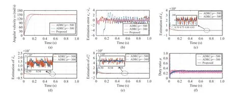
Fig.9.Response curves when ω∗=150 rad/s (a) Angular velocity;(b) Estimation error;(c) Estimation of ;(d) Estimation of ;(e) Estimation of ;(f) Control input μ).
杂志排行
IEEE/CAA Journal of Automatica Sinica的其它文章
- Sampling Methods for Efficient Training of Graph Convolutional Networks:A Survey
- Fault Accommodation for a Class of Nonlinear Uncertain Systems With Event-Triggered Input
- Precise Agriculture:Effective Deep Learning Strategies to Detect Pest Insects
- Maximizing Convergence Speed for Second Order Consensus in Leaderless Multi-Agent Systems
- Exponential Set-Point Stabilization of Underactuated Vehicles Moving in Three-Dimensional Space
- An Adaptive Rapidly-Exploring Random Tree
