Exponential Set-Point Stabilization of Underactuated Vehicles Moving in Three-Dimensional Space
2022-01-25XiaodongHeZhiyongSunZhiyongGengandAndersRobertssonSenior
Xiaodong He,Zhiyong Sun,,Zhiyong Geng,and Anders Robertsson, Senior
Abstract—This paper investigates the stabilization of underactuated vehicles moving in a three-dimensional vector space.The vehicle’s model is established on the matrix Lie group SE(3),which describes the configuration of rigid bodies globally and uniquely.We focus on the kinematic model of the underactuated vehicle,which features an underactuation form that has no sway and heave velocity.To compensate for the lack of these two velocities,we construct additional rotation matrices to generate a motion of rotation coupled with translation.Then,the state feedback is designed with the help of the logarithmic map,and we prove that the proposed control law can exponentially stabilize the underactuated vehicle to the identity group element with an almost global domain of attraction.Later,the presented control strategy is extended to set-point stabilization in the sense that the underactuated vehicle can be stabilized to an arbitrary desired configuration specified in advance.Finally,simulation examples are provided to verify the effectiveness of the stabilization controller.
I.INTRODUCTION
OVER the past two decades,a large amount of attention has been paid to the control of different kinds of vehicles such as ground vehicles,autonomous underwater vehicles(AUVs),unmanned aerial vehicles,etc.In practice,for the purpose of weight and cost reduction,vehicles are generally designed with fewer actuators than degrees of freedom (DOF),resulting in underactuated systems.From the kinematic level of a vehicle moving in the three-dimensional vector space R3,a typical form of underactuation is that the vehicle has no sway and heave velocity,while only one surge velocity and three angular velocities serve as control inputs.Such a system model can be utilized to describe the kinematics of autonomous underwater vehicles [1]–[4],unmanned aerial vehicles [5]–[8],and so on.Although it is quite appealing to control more states with fewer inputs,the stabilization of the underactuated vehicle is a nontrivial problem,owing to the fact that,according to Brockett’s theorem [9],underactuated vehicles cannot be stabilized to a constant equilibrium via continuous time-invariant feedback.
Thus,in order to overcome the problem,a variety of control strategies are applied to the underactuated vehicle’s stabilization,such as continuous time-varying feedback [10],[11],discontinuous time-invariant feedback [12],[13],and switched control [14],[15].For instance,a continuous timevarying feedback is presented in [16] based on the properties of homogeneous system as well as the averaging and Lyapunov techniques,and the controller can locally exponentially stabilize an underactuated vehicle system.In[17],the authors present a methodology called switched seesaw control for the stabilization of underactuated vehicles,in which input-to-state practical stability is obtained under the provided conditions.The authors in [18] investigate the control of underactuated vehicles using dipolar reference vector fields combined with viability theory,where the proposed controller guarantees the convergence in a neighborhood of the desired configuration.An asymptotically stable switching control algorithm is provided in [19],where the model of the underactuated vehicle is converted to a cascade nonlinear system by an appropriate state transformation so that general properties of cascade systems are utilized in the stability analysis.In [20],a novel model predictive control law based on the system’s homogeneity and an existing time-varying controller is designed,where asymptotic stability can be ensured under the proper terminal set level and cost weights.In [21],a three-dimensional pathfollowing control strategy for an underactuated airship is proposed based on the guidance of parameterized paths,where the system is transformed to a cascaded formulation.Also,the approach of the cascaded structure is utilized in other underactuated mechanical systems to handle underactuation.For example,the authors in [22] present a new cascaded extended state observer for an underactuated flexible joint robot.In [23],an active disturbance rejection control scheme is proposed for underactuated systems like the Furuta pendulum.
In the aforementioned articles,the attitude of the underactuated vehicle is described by either Euler angles or unit quaternions.However,it is pointed out in [24] that the configuration manifold for the attitude of rigid bodies moving in R3is the three-dimensional matrix Lie group SO(3),where SO(3)is the group of rotation matrices.Although Euler angles provide a straightforward means of parameterizing the matrix in SO(3),they are only locally effective and suffer from singularity when describing the attitude.Unit quaternions offer a globally nonsingular parametrization of SO(3),but have the drawback of sign ambiguity,caused by the two-toone map fromS3to SO(3),whereS3is the set of unit quaternions.Then,the controller designed by quaternions makes the attitude response exhibit an unwinding phenomenon [25].Thus,it would be much better to establish the model on the Lie group SO(3),which is a kind of global and unique descriptions for the vehicle’s attitude.
Moreover,it is worth paying attention to the domain of attraction for the underactuated vehicle’s stabilization.Generally,we would like to enlarge the domain of attraction,preferably a global domain.Nevertheless,as illustrated in[25],due to the topological obstruction,no continuous vector field on a compact manifold can have a globally asymptotically stable equilibrium point.When applying this fact to the problem of rigid body attitude stabilization,where the state is the flow of a vector field on the compact manifold SO(3),we reach the conclusion that the rigid body’s attitude cannot be globally stabilized [26].Note that,herein,global stability means the closed-loop system is stable from any initial condition chosen on the manifold SO(3).Thus,regarding the underactuated vehicle’s stabilization,as pointed out in [26],at best one can claim an almost global domain of attraction,which means the initial condition can be arbitrarily chosen on S O(3) except for certain sets of points with measure zero.Although many existing articles claim global stability for underactuated vehicle’s stabilization,the closed-loop system is actually only globally stable in the subset which is obtained by local diffeomorphisms on S O(3).
In this paper,we establish the model of underactuated vehicles on the matrix Lie group S E(3)=SO(3)⋉R3,where⋉denotes the semi-direct product,and study the problem of the underactuated vehicle’s stabilization to a desired equilibrium.Under such a framework,the model of the underactuated vehicle is independent of any local coordinates.Note that the configuration of the underactuated vehicle is on the Lie group,while its velocity is in the Lie algebra,which is the tangent space at the identity group element with the Lie bracket defined by matrix commutator.Thus,one of the difficulties is how to construct the state feedback between different spaces,that is,from the Lie group to the Lie algebra.
Another challenge arises from the underactuation characteristics.For underactuated systems,given the fact that the number of independent control inputs is fewer than the degrees of freedom,it is a challenging problem to design feasible controllers that compensate for the impact arising from the system’s underactuation.The main idea in this paper is to make the state variables in underactuated directions coupled with the feedback in actuated directions,so that those“underactuated states” can be driven by the control inputs.Regarding the underactuated vehicle,it is modelled without sway and heave velocity,which is similar to the nonholonomic constraint.Thus,we should make the underactuated vehicle’s rotation components coupled with the translation components.Only by using an additional rotation related with the motion of translation can the underactuated vehicle be possibly stabilized.However,it is not trivial to design a controller so as to make these two parts of different states appropriately coupled.Although a number of papers focus on the three-DOF nonholonomic ground vehicle evolving on SE(2),such as [27]–[30],the six-DOF nonholonomic vehicle on S E(3) is rarely considered.
The contributions of this paper are elaborated below.
1) We firstly transfer the underactuated vehicle’s states from the Lie group to the Lie algebra with the help of the logarithmic map,which is almost global on the Lie group SE(3).After that,we construct two rotation matrices based on the translation components of the states in the Lie algebra.Since the additional rotation matrices are designed by translation states,such a construction makes the translation state variables in underactuated directions coupled with the motions of rotation which are fully actuated.Moreover,the additional rotation matrices are constructed based on both rigorous mathematical tools and clear physical backgrounds,so that they can be explained intuitively and explicitly from a physical point of view.
2) Following the constructed rotation matrices,we propose the logarithmic state feedback for the underactuated vehicle,where the logarithm of the constructed matrices serves as the additional angular velocity to compensate for the nonexisting sway and heave velocity.In this way,the translation state variables in underactuated directions can be controlled by the coupling effect with the motions of rotation.Furthermore,by dint of the Lyapunov theorem,we prove that the presented control law can exponentially stabilize the underactuated vehicle to the identity group element with the almost global domain of convergence.That is to say,the underactuated vehicle can start from any point on SE(3) except for several points with measure zero.
3) By designing a new group element related with a constant configuration,we propose a feasible controller which exponentially stabilizes the underactuated vehicle to an arbitrary desired configuration specified in advance.In other words,the presented control strategy can achieve exponential set-point stabilization of the underactuated vehicle.
The rest of the paper is organized as follows.In Section II,we provide preliminaries of the Lie group S E(3) and formulate the stabilization problem on SE(3).The control strategy is presented in Section III,including stabilization to the identity group element and to the predefined constant configuration.Numerical simulation examples are given in Section IV.The whole paper concludes in Section V.
Several commonly-used notations are defined in advance.The identity matrix in Rnis denoted byIn.The base vectors of R3are denoted bye1,e2,e3.The symbol 0m×nrepresents a matrix in Rm×nwith all zero components.Moreover,variables denoting vectors and matrices are written in bold,while those denoting scalars are not.
II.PRELIMINARIES AND PROBLEM FORMULATION
A.Kinematics on Special Euclidean Group SE(3)
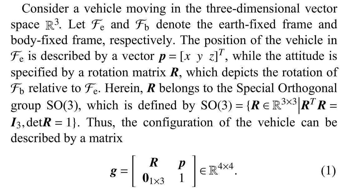
Sincegcan be uniquely defined by a rotation matrixRand a position vectorp,the configuration of the vehicle can also be simply denoted byg=(R,p).All the configurationsg,with matrix multiplication as group operation,constitute a matrix Lie group named the special Euclidean group SE(3),that is,
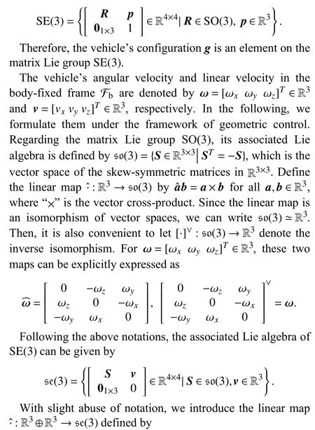
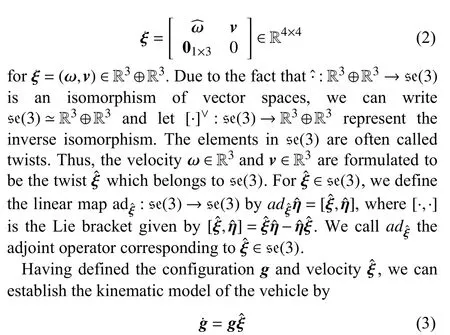
wheregis regarded as the state andis the control input.Obviously,the system (3) is independent of local coordinates.Although the vehicle has six DOFs,it is assumed that the linear velocity along they-axis andz-axis of Fbare set to be zero,that is,

Hence,there are only four available control inputs,i.e.,vx,ωx,ωy,ωz,which renders an underactuated vehicle system.Under such an input setting,it can be verified that the Lie algebra controllability rank condition is satisfied,indicating that the underactuated vehicle is controllable.Furthermore,by computing the Lie bracketswe have

B.Logarithmic Map
According to the definition ofgand,the state of the underactuated vehicle system (3) evolves on the matrix Lie group SE(3),while the control input lies in the Lie algebra se(3).In order to construct state feedback,the configurationghas to be transformed from SE(3) to se(3).To this end,we utilize the logarithmic map which is introduced in the lemma below.
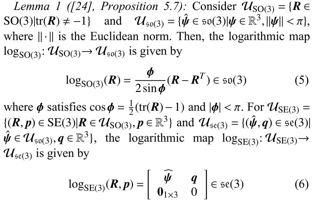
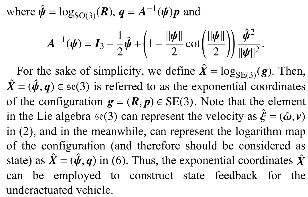
Another fact which should be noted is that the logarithmic map is not globally defined on the whole SE(3),since it suffers from ambiguity at the point tr(R)=−1 on SO(3),which is explained as follows.As illustrated in [24],the logarithmic map logSO(3)for a rotation matrixRis related to the notion of angle and axis of rotation.To be more specific,the attitudeR∈SO(3) is equivalent to a rotation about a fixed axis ℓ ∈R3through an angleθ,whereθ=arccos((tr(R)−1))and
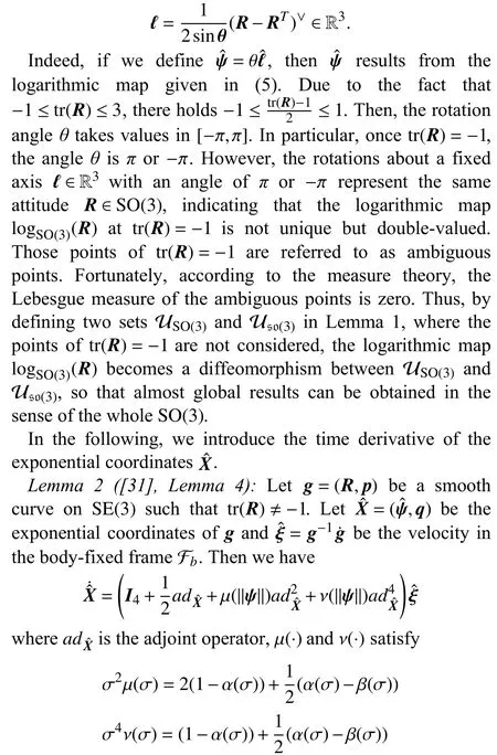
and α(σ)=(σ/2)cot(σ/2),β(σ)=(σ/2)2sin2(σ/2),for σ ∈R.If we define
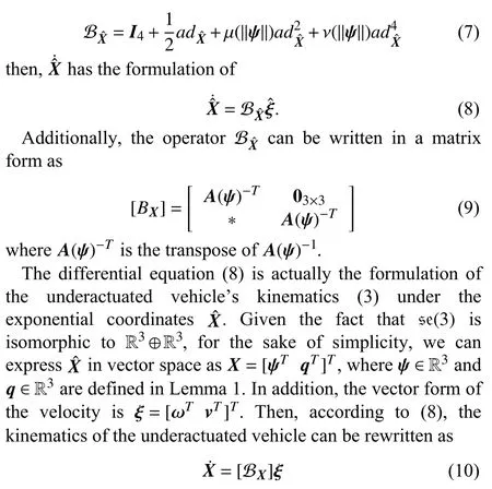
where [ BX] is provided in (9).
C.Problem Formulation
The control objective of this paper is to stabilize the underactuated vehicle to an arbitrary desired position with specified attitude.Letgd=(Rd,pd) denote the desired configuration,whereRdandpdrepresent the predefined attitude matrix and position vector,respectively.Then,the problem can be formulated as designing a control strategyfor system (3) such that the stategsatisfies

Particularly,if we would like to stabilize the underactuated vehicle to the origin of the earth-fixed frame Fe,and meanwhile,make the underactuated vehicle’s body-fixed frame Fbhave the same direction as Fe,then it holdsRd=I3andp=03×1,in other words,gd=I4.Thus,the control objective (11) degenerates to

Note that when the componentsvyandvzinare 0,we can merely employ the angular velocity ωˆ and the linear velocityvxas control inputs to stabilize the underactuated vehicle.
In addition to the mission of makinggconvergent,we would like to have the domain of convergence as large as possible.Under the exponential coordinates,although global convergence cannot be derived due to the existence of certain ambiguous points,it is still possible to make the closed-loop system almost globally stable.The definition of almost global stability on SE (3) is provided below.
Definition 1 (Almost Global Stability on SE (3)):Letg(t,g0,)denote the solution of the system (3) under the initial conditiong0and control input.If for any initial conditiong0=(R0,p0) satisfying tr(R0)≠−1,there always holds then the equilibriumg=I4is almost globally asymptotically stable.Moreover,if the solutiong(t,g0,) converges toI4exponentially,then the equilibrium is almost globally exponentially stable.

Note that the identity group elementg=I4corresponds to=0 under the logarithmic map=logSE(3)(g).Thus,the underactuated vehicle’s configurationgis stabilized to the identity element if and only ifis driven to zero.
We conclude this section with a technical lemma which illustrates the exponential stability of a nonlinear system,and this lemma will be utilized in later stability analysis of the closed-loop system.
Lemma 3 ([32],Theorem 4.10):Consider the system=f(t,x),wheref:[0,∞)×D→Rnis piecewise continuous intand locally Lipschitz inxon [0,∞)×D,andD⊂Rnis a domain that contains the originx=0.Letx=0 be an equilibrium point for=f(t,x).LetV(t,x) be a continuous differentiable function such that

for all (t,x)∈[0,∞)×Dand for some positive constantsc1,c2,c3.Then,x=0 is exponentially stable.
III.CONTROL STRATEGY
In this section,we propose the control strategy to stabilize the underactuated vehicle.For systems evolving in the Euclidean space,the stabilization to a given equilibrium can be reduced to the stabilization to the origin via an appropriate state transformation.Similarly,we firstly consider the problem of stabilizing the underactuated vehicle’s configuration to the identity element,and then focus on the stabilization to an arbitrary desired configuration.
A.Stabilization to the Identity Element
Regarding fully actuated systems on SE(3),the control lawcan exponentially stabilize the state to the identity element [31].Following this idea,we can design a feedback with the aid of the exponential coordinatesto stabilize the underactuated vehicle.Given the fact that the underactuated vehicle does not have linear velocity along they-axis andzaxis,i.e.,vy=vz=0,we will construct additional angular velocity around thez-axis andy-axis respectively so as to compensate for the lack of linear velocityvyandvz.
From Lemma 1,the exponential coordinates ofgare=logSO(3)(R) andq=A−1(ψ)p.Sinceqis a vector in R3,we useqi(i=1,2,3) to denote theith component,so that

We firstly construct a rotation matrix around thez-axis.Define a vectorn=[q1q20]Tand normalize it as

Then,we define another vector
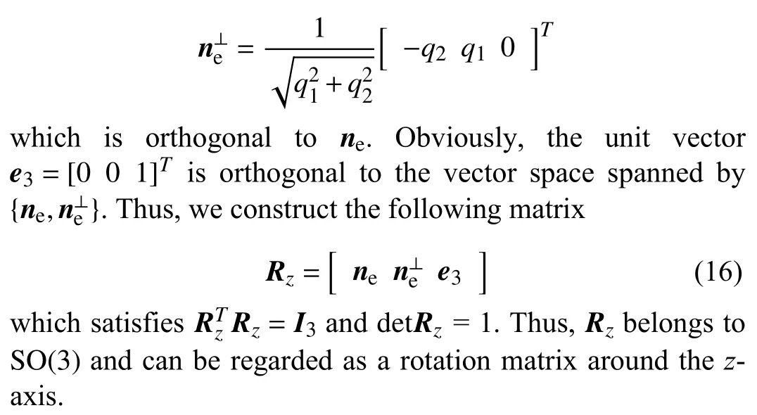
Similarly,we can design another rotation matrix around they-axis.Define a vectorm=[q10q3]Twhose normalized vector is
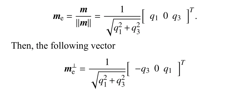
is orthogonal tome.Therefore,with the unit vectore2=[0 1 0]T,we can construct a rotation matrix around they-axis as

Due to the fact thatRzandRyare both in S O(3),according to (5),we can obtain their exponential coordinates by
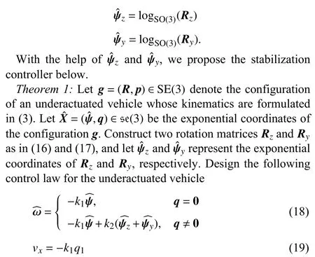
wherek1andk2are positive scalars.Then,the identity elementI4is an equilibrium of the closed-loop system which is almost globally exponentially stable.
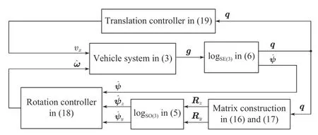
Fig.1.Block diagram of the closed-loop system.
The block diagram of the closed-loop system is given in Fig.1.As shown in the figure,we firstly operate the logarithmic map logSE(3)on the AUV’s configurationgto obtain exponential coordinatesis the rotation component andqis the translation component.Then,the translation componentqis utilized to construct two rotation matricesRzandRy.In this way,the translation state variables in the underactuated directions are made coupled with the motion of rotation.Next,the constructed rotation matricesRzandRyare operated via the logarithmic map logSO(3)so as to obtainwhich serve as the additional angular velocities for the AUV.Therefore,due to the effect of coupling,the translation state variables in the underactuated directions can be stabilized by the additional angular velocities,which demonstrates how to deal with the underactuation of the system.Regarding the rotation and translation state variables in the actuated directions,they can be stabilized by the feedback ofandq1,respectively.
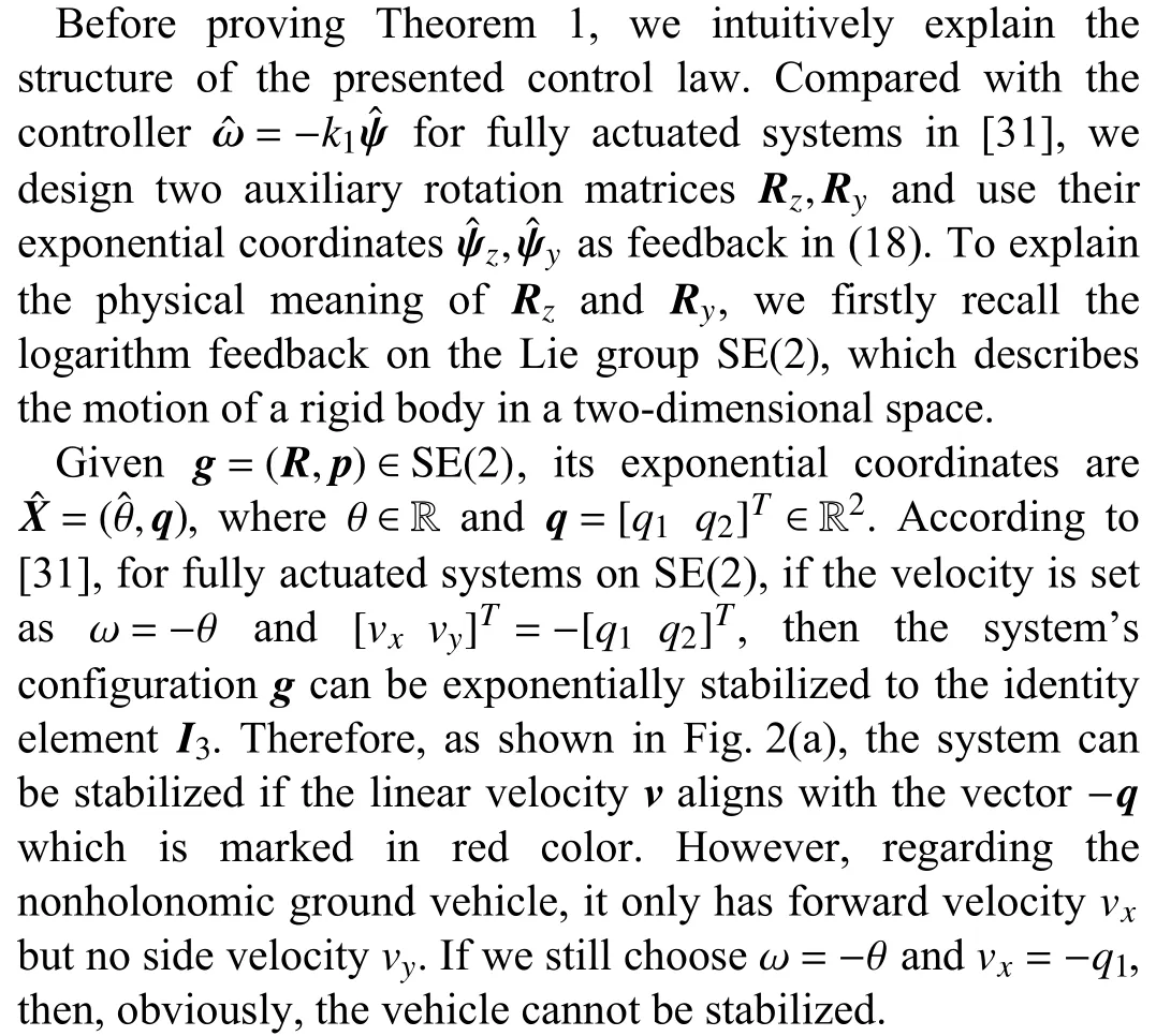
Now that the red vector in Fig.2(a) is the direction of the velocityvwhich can achieve stabilization,we can rotate the orientation of the nonholonomic vehicle such thatvxhas the same direction as the red vector,as shown in Fig.2(b).To this end,we construct an additional angular velocity proportional toϑ,which is the angle given by ϑ=arctan(q2/q1).Thus,we can design the following stabilization controller for the nonholonomic vehicle

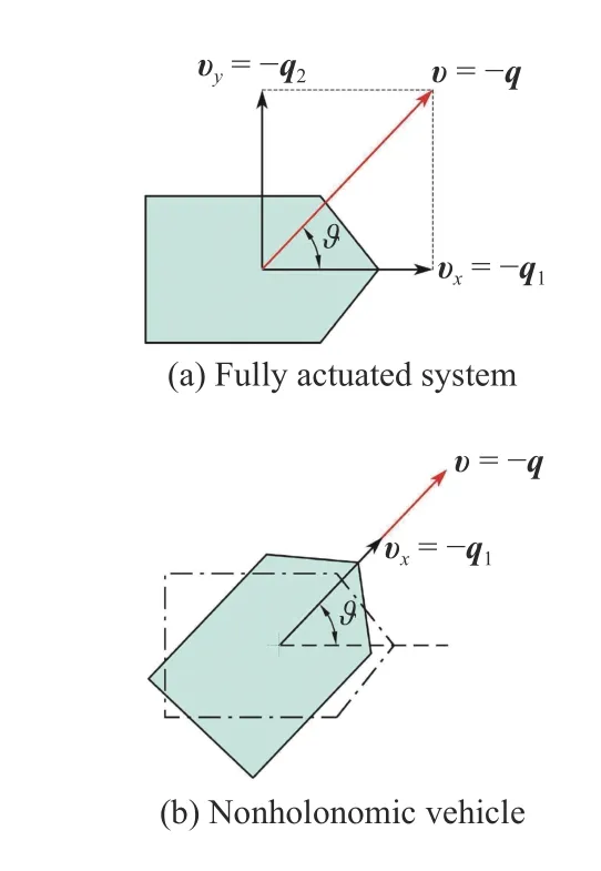
Fig.2.Logarithmic feedback on S E(2).
wherekis a positive scalar.This control law is motivated by the factwhere [·,·] is the Lie bracket andis the control vector field along the direction of ⋆.This shows that additional rotation can possibly compensate for the lack of side velocity.In the control law,intuitively,the additional angular velocitykϑ rotates the nonholonomic vehicle to make its velocity aligned with the velocity of a fully actuated system,so that the nonholonomic vehicle can converge to the origin by “following” the trajectory of fully actuated system.In this sense,kϑ is interpreted as an additional rotation to compensate for the nonexistence ofvy.Of course,it can be proved that the controllers (20) and (21) asymptotically stabilize the nonholonomic vehicle’s configuration to the identity element [33].
Actually,ϑis the exponential coordinate of a rotation matrix on S O(2),i.e.,ϑ=(logSO(2)())∨,where

andrepresents the rotation ofqrelative toq1shown in Fig.2(a).Thus,the additional angular velocitykϑ in (20) can be regarded as a proportional feedback to the exponential coordinates of the constructed rotation matrix.
Now,we turn to the stabilization of the underactuated vehicle on SE(3).According to (4),the underactuated vehicle does not have velocity along they-axis andz-axis of the bodyfixed frame Fb,but only has one linear velocityvx.Motivated by the controller designed for the nonholonomic vehicle,we utilize the exponential coordinates=(,q) for feedback,and meanwhile add extra angular velocityandwhich are the exponential coordinates of the constructed rotation matricesRzandRy,respectively.
The construction ofRzandRyis similar toin (22),but their dimension is lifted so as to be compatible with SO(3).From the definition in (16),Rzis to rotatevxinx−yplane to compensate forvy.Similarly,Rydesigned in (17) is to rotatevxinz−xplane to compensate forvz.Note that such rotation ofvxactually rotates the body-fixed frame Fb,in other words,it changes the attitude of the underactuated vehicle,sincevxis always aligned with thex-axis of Fb.Therefore,after rotation,the only linear velocityvxcan point to an appropriate direction (in fact the direction of −q),so as to make the underactuated vehicle converge to the origin.
Although the ideas of designing controllers to compensate for underactuation on SE(2) and SE(3) are similar to some extent,the stability analysis and theoretical proofs in these two cases are totally different.For the case of SE(2),the closed-loop system is transformed from the Lie group SE(2)to the Lie algebra se(2) by the logarithmic map l ogSE(2).More importantly,the system can then be transformed to the vector space R3,which is isomorphic to the Lie algebra se(2).In this way,the stability can be proved based on the explicit formulation in R3with the techniques of inequalities.However,when it comes to SE(3),although the closed-loop system can be similarly transformed to the Lie algebra se(3)by the logarithmic map logSE(3),it is difficult to further obtain an explicit formulation in the vector space R6,which is isomorphic to se(3).Thus,as provided in the following subsection,in order to analyze the stability,we firstly define a positive invariant set,and then derive the boundness of eigenvalues of the system matrix.Finally,by utilizing some inequalities,we prove the exponential stability of the closedloop system.Therefore,the stability analysis in the cases of SE(2) and SE(3) are completely different,and the proof on SE(3)is much more involved.
B.Stability Analysis
In this subsection we present the proof of the main result in Theorem 1.Although the structure of the proposed controller is not complicated,analyzing the stability of the closed-loop system is rather involved.The difficulties arise from two aspects.On the one hand,in the exponential coordinates,the system’s dynamics contains a state-dependent term,which brings strong nonlinearity to the stability analysis.On the other hand,the constructed additional angular velocityis related to the translation components,which makes the rotation and translation coupled with each other,so that the technical tools for cascade systems cannot be applied herein.
To overcome these difficulties,we discuss the stability from two cases based on the formulation of Lyapunov function.Later,by estimating a series of inequalities,we obtain a condition which guarantees the exponential stability of the closed-loop system.The whole proof of Theorem 1 is provided as follows.
Proof:Our mission is to proveg(t)→I4ast→∞.By transforming the state from S E(3) to s e(3) with the logarithmic map logSE(3),and using the fact that se(3) is isomorphic to R3⊕R3,the objective can be transformed to the proof ofX(t)=
The situation ofq=0 is fairly simple to deal with.Under such a situation,we merely have to considerψ,whose time derivative is=ω.According to (18),the closed-loop system becomes=−k1ψ,which is obviously a first-order system with exponential stability.Thus,in the following,we pay much attention to the situation ofq≠0.
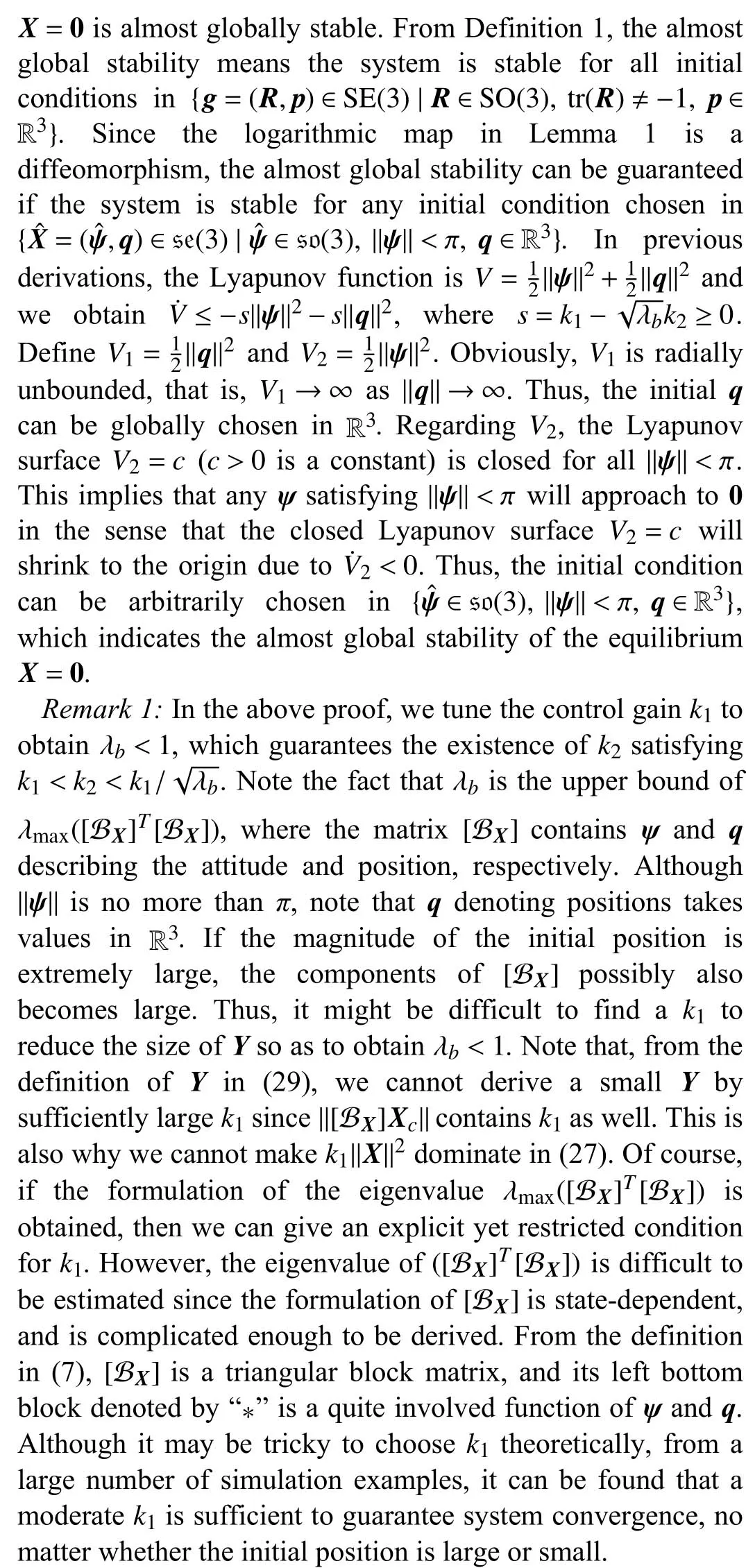
From the control law in (18) and (19),the underactuated vehicle’s velocityξcan be written as

whereq c=[0q2q3]T.Define a new vector
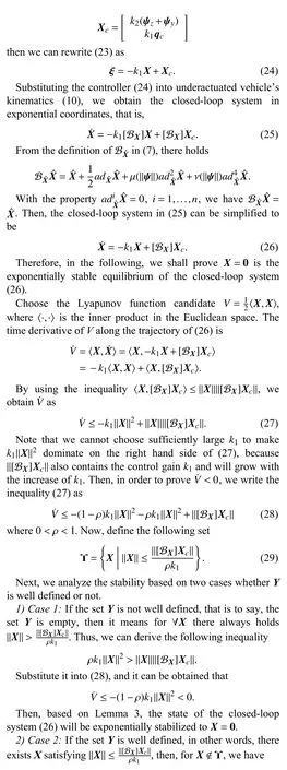
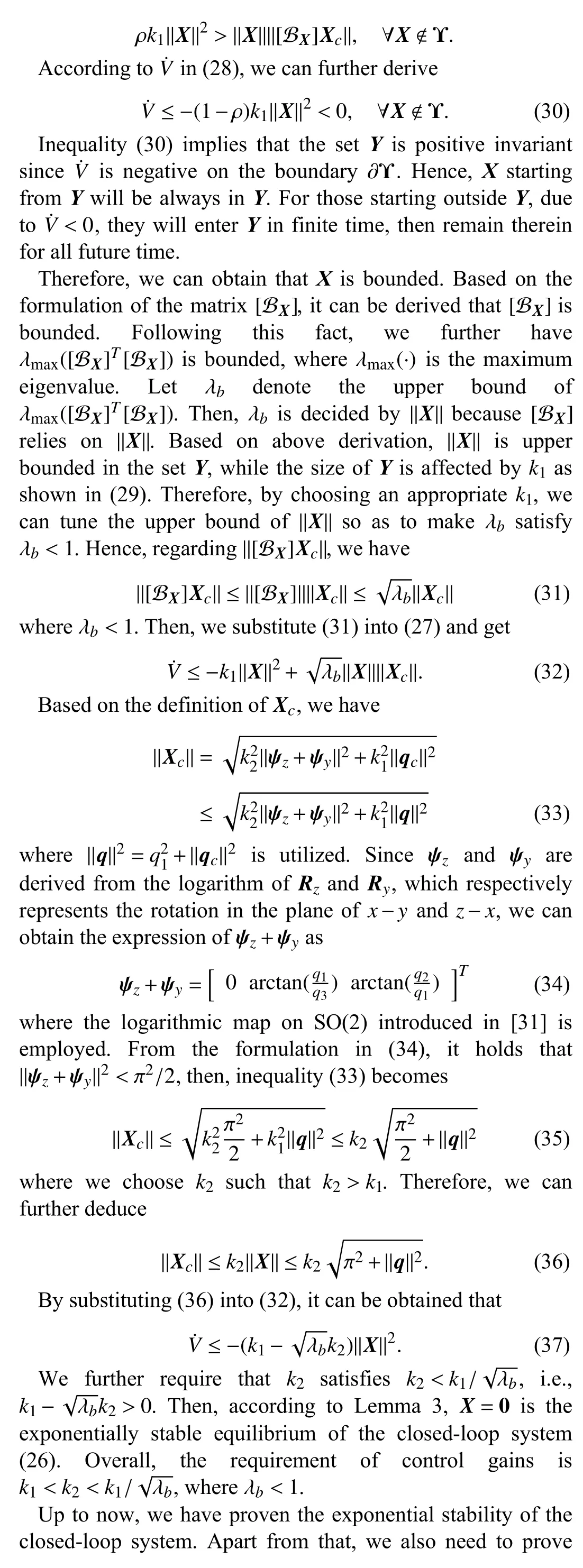
Remark 2:Since the velocityvy,vzof the underactuated vehicle is set to be 0,the vehicle can be regarded as a nonholonomic system in three-dimensional space.According to the Brockett’s theorem,nonholonomic systems cannot be stabilized to a constant equilibrium via continuous timeinvariant feedback.From (18),the angular velocityωhas a discontinuous form,which corresponds to the Brockett’s theorem.The discontinuity ofωresults from the fact that the constructed matricesRz,Ryare not well defined atq=0 according to the definition in (16) and (17).Then,we set the additional angular velocity ψz,ψyto be 0 atq=0.In fact,such an operation is reasonable and can be intuitively explained as follows.Based on the definition in Lemma 1,q=0 means the underactuated vehicle is at the origin of the earth-fixed frame Fe,i.e.,p=0.Note that the additional angular velocities ψz,ψyare to compensate for the nonexistencevy,vz.In other words,the variables ψz,ψyare designed to make the position converge to the origin.Thus,onceqconverges to 0,the additional angular velocity is no longer necessary,so that we can let ψz=ψy=0atq=0.
C.Stabilization to an Arbitrary Configuration
We have presented the control strategy in Theorem 1 that stabilizes the underactuated vehicle’s configuration to the identity element.This result can be extended to the problem of stabilizing the underactuated vehicle to an arbitrary point specified in advance,that is,achieving set-point stabilization.Note that,herein,the point refers to a configuration on S E(3),which means the desired position and attitude can be both predefined.In the following,we will derive the set-point stabilization controller based on Theorem 1.
Letgd=(Rd,pd) denote the desired constant configuration.Referring to the definition of error on Lie groups,we define a new element

which is defined in the body frame ofgdand also belongs to SE(3).Generally,his called the relative configuration ofgwith respect togd,and it can be intuitively regarded as the error betweengandgd.If we can makehconverge to the identity elementI4,that is,

thengreaches the desired configurationgd.To this end,we firstly derive the dynamics ofhas follows.Taking the time derivative ofh,we have

Substitute (3) into (39),then there holds

where the definition ofhin (38) is utilized.Compared with the underactuated vehicle’s kinematics in (3),the differential equation (40) describes an underactuated-vehicle-like system evolving on SE(3),whose state ishand input is.Therefore,the configurationhcan be stabilized to the identity elementI4under the controller proposed in Theorem 1,which implies a modified controller to stabilizegto the desired configurationgd.The result is summarized in the theorem below.
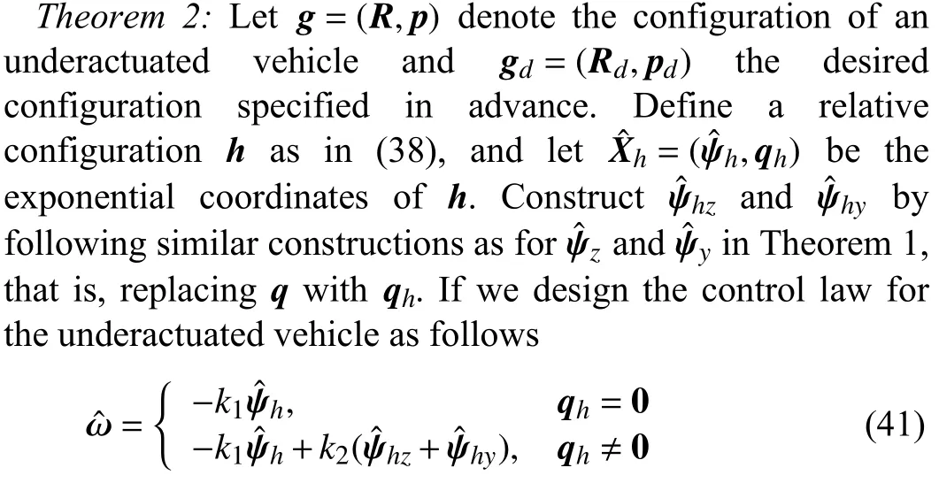

wheree1=[1 0 0]T,k1andk2are positive scalars,then,the desired configurationgdis the equilibrium of the closed-loop system which is almost globally exponentially stable.
IV.NUMERICAL SIMULATION
In this section,we provide five simulation examples to verify the effectiveness of the proposed controller.In addition,we apply the system model of the underactuated vehicle given in (3) to the autonomous underwater vehicle (AUV),similar to the models in [1]–[3].
The first example is to stabilize the AUV to the identity configuration by using Theorem 1.The initial attitude matrixR0and initial position vectorp0are chosen as

The control gains are set to bek1=2,k2=7 and the simulation time is 10 s.Note that in order to avoid a velocity step at the initial time,an exponential decay factoris multiplied in front of the controller.The simulation results are shown in Figs.3–5.The configuration of the AUV is depicted in Fig.3.For the sake of graphical illustration,we use Euler angles (roll,pitch,yaw) to describe the attitude.As is shown in the figure,both of the Euler angles and positionsx,y,zconverge to zero,which indicates that the AUV’s configuration is stabilized to the identity element.Fig.4 shows the AUV’s velocity which serves as the control input.It can be observed that there are only four inputs and the linear velocityvyandvzare always zero,which verifies the underactuation of the AUV.The AUV’s trajectory is provided in Fig.5,where the evolution of the attitude is also depicted by exhibiting the body frame attached to the center of mass of the AUV.In order to illustrate the AUV’s attitude clearly,we mark thex-,y-,z-axis of the body-fixed frame Fbin red,green and blue color,respectively.It is shown that the AUV finally converges to the origin of the earth-fixed frame Fe,and has the same direction as Fe.
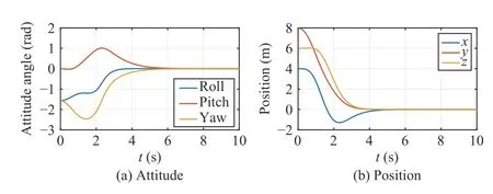
Fig.3.Evolutions of AUV’s configuration with time.
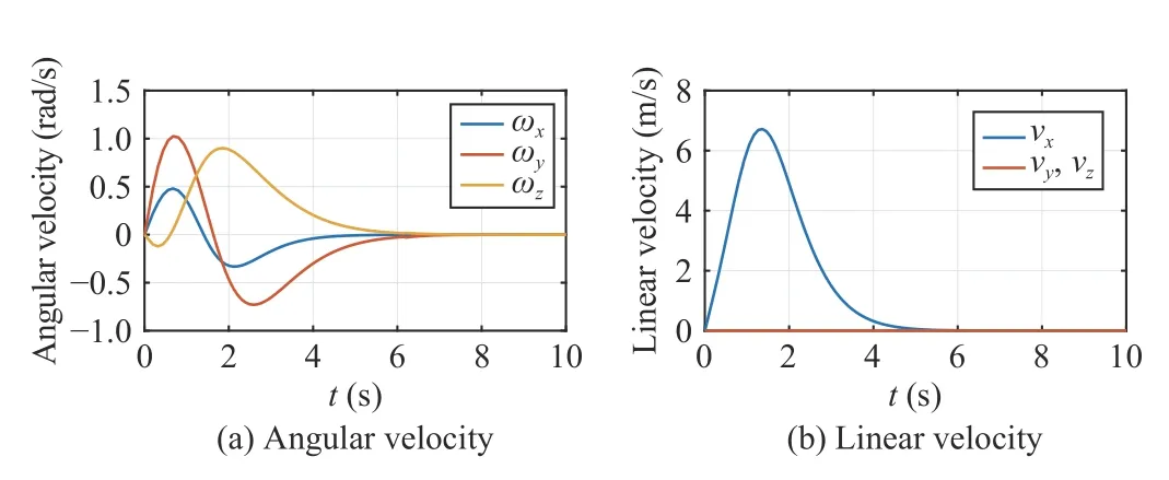
Fig.4.Evolutions of AUV’s angular velocity and linear velocity with time.
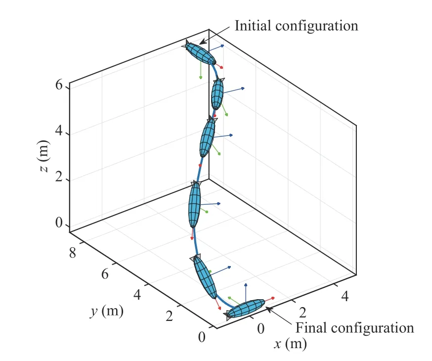
Fig.5.Trajectory of AUV stabilized to the identity element.
The second example is to intuitively show the meaning of the control gains,where the simulation are performed in two cases of different control gains.In Case 1 (C1) and Case 2(C2),the gains are set to bek1=2,k2=6 andk1=2,k2=20,respectively.The AUV’s initial attitude matrixR0and initial position vectorp0are chosen as

The AUV’s trajectories under the gains ofk1=2,k2=6 andk1=2,k2=20are given in Fig.6.The configuration and velocity evolution of the AUV are given in Figs.7 and 8,respectively.As shown in Fig.6,with a larger value ofk2/k1,the AUV would adjust its orientation to the desired orientation more quickly.In Fig.6(a),when the AUV’s position is near the origin,its orientation is still quite different from the desired orientation,so that it should adjust its attitude in a short time to make the attitude convergent.In contrast,the AUV in Fig.6(b) adjusts the attitude earlier;thus,when approaching the origin,it can converge to the desired orientation more steadily and smoothly,avoiding a large maneuver in a short time.It can also be observed from Fig.7(a) that the convergence of the AUV’s attitude in Case 1 is slower than that in Case 2.Such a phenomenon results from the fact thatk2is the coefficient before the term,which is the additional angular velocity to compensate for the underactuation.Thus,a larger control gaink2will result in a more obvious compensation to the rotation dynamics,indicating that the AUV will adjust its orientation more quickly so as to converge to the origin more “smoothly”.
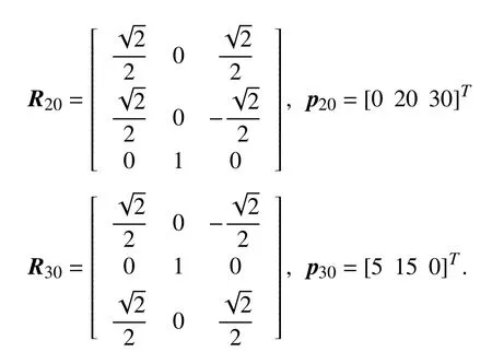
In the third example,with the aid of Theorem 2,the AUV is stabilized to a desired configuration specified in advance.In the numerical simulation,we consider three AUVs which are to be controlled to their respective desired configurations.The initial attitude matrixRi0and initial position vectorpi0for the AUVi(i=1,2,3) are set as
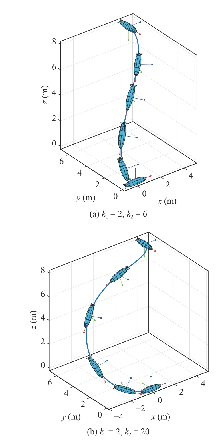
Fig.6.Trajectories of AUV under different control gains.
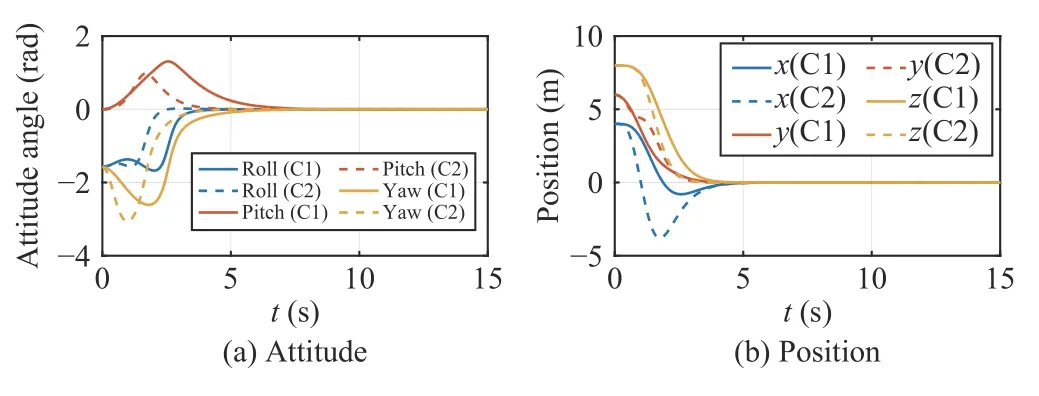
Fig.7.AUV’s configuration under different control gains (C1:k1=2,k2=6;C2:k1=2,k2=20).
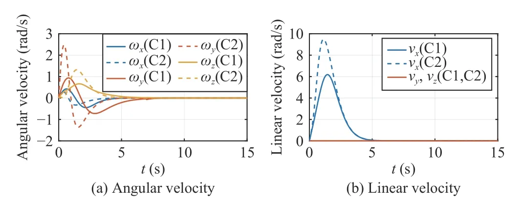
Fig.8.AUV’s velocity under different control gains (C1:k1=2,k2=6;C2:k1=2,k2=20).

Before specifying the desired configuration,we define the following three rotation matricesRx,Ry,Rz,which respectively represent the rotation around thex-,y-,z-axis of the body-fixed frame Fb,that is,
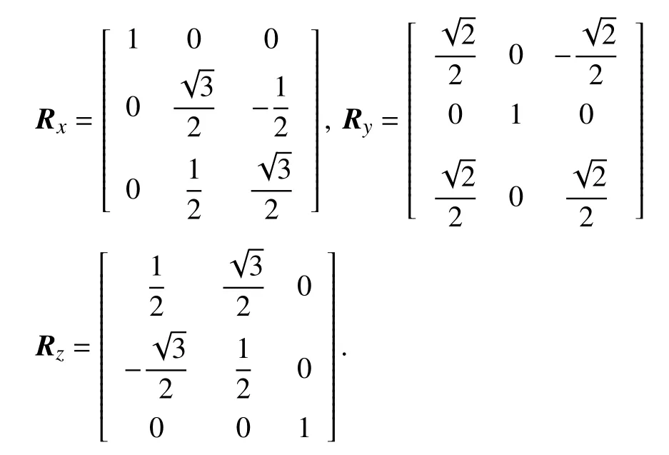
Then,we can define another rotation matrix by

which represents the attitude of the AUV after the consecutive rotation ofRx,Ry,Rz.The desired attitude of the three AUVs are all specified to beR1d=R2d=R3d=Rxyz,and the desired position vectors arep1d=[30 20 15]T,p2d=[30 15 15]Tandp3d=[30 25 15]T.The simulation result is provided in Fig.9,which shows that all of the three AUVs are stabilized to their desired configurations from their respective initial conditions.
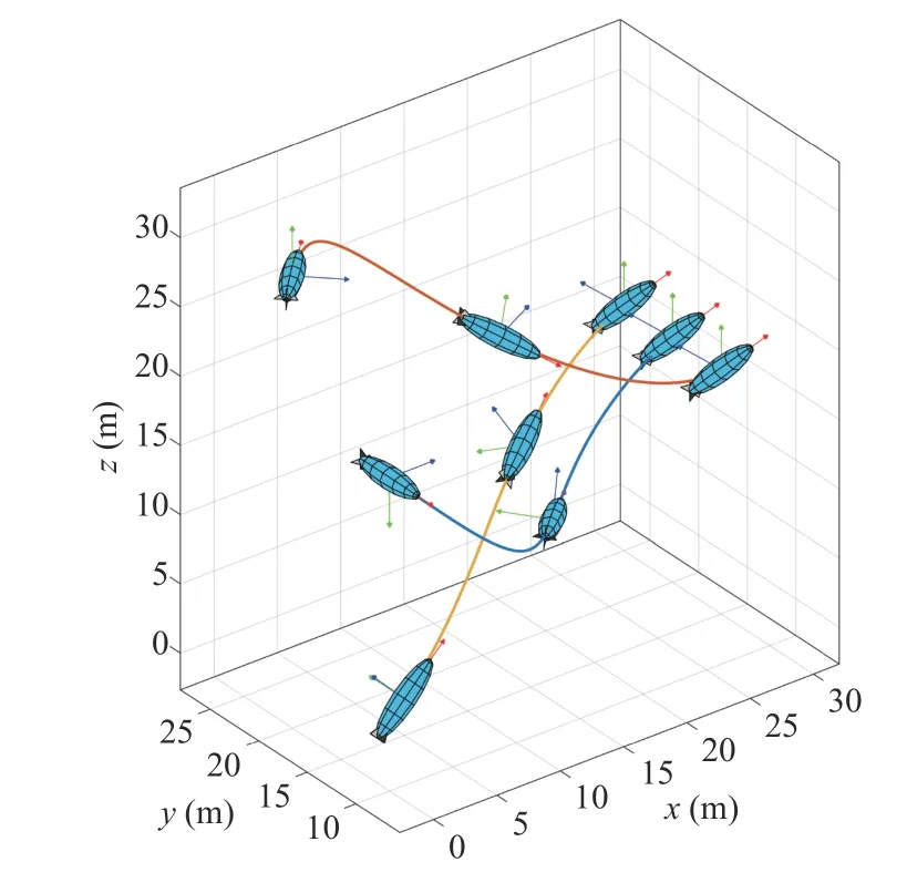
Fig.9.Trajectory of AUV stabilized to a desired configuration.
The fourth example is to show that the proposed controller is robust to nonlinear disturbances from the ambient environment.Consider a bounded time-varying environmental disturbance on the angular velocity as follows

Thus,the total angular velocity of the AUV should be


The control gains are set to bek1=3,k2=10.We substitute the angular velocityin (44) and the linear velocityvxin(19) into the AUV’s kinematics (3),so as to obtain the closedloop system for the simulation.The simulation results are provided in Figs.10 and 11,which show the evolution of the AUV’s configuration and velocity,respectively.It can be observed from Fig.10(a) that the attitude angles converge to a small neighborhood of the origin,implying that the controller is robust to bounded nonlinear disturbances.
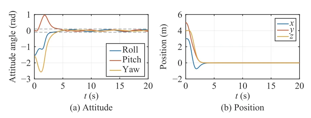
Fig.10.AUV’s configuration under bounded nonlinear disturbances.
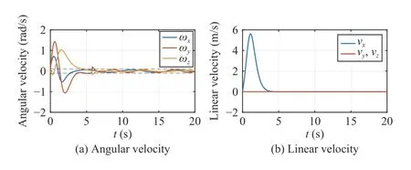
Fig.11.AUV’s velocity under bounded nonlinear disturbances.
In the fifth example,we present comparisons between the stabilization controller in this paper and that in [11].In the numerical simulation,the AUV’s initial attitude matrixR0and initial position vectorp0are chosen as

The simulation results under the two different controllers are provided in Figs.12–15.Specifically,Figs.12 and 13 show the attitude and position evolution,while Figs.14 and 15 provide the angular and linear velocity.By comparison,it can be seen that under the controller in this paper,the AUV has little or no oscillation during the transient period,while the configuration (especially the attitude) of the AUV in [11]oscillates rather seriously.This is because a sine function of timetis employed in the controller of [11],which makes the controller become time-varying and periodical.Furthermore,the controller in this paper can stabilize the AUV in about 35 s.In contrast,the convergence time of the controller proposed in [11] is longer than 150 s.Although the convergence time is directly related to the magnitude of control inputs,it can be observed from Figs.14 and 15 that magnitude of the velocities are relatively similar between these two controllers.Therefore,compared with [11],the controller proposed in this paper has a better transient performance and shorter convergence time.These advantages result from the fact that the proposed controller,especially the constructed rotation matrix,is designed based on the physical background of the AUV.In other words,the controller has an intuitive and explicit physical explanation,which is a critical point for the control design of mechanical systems.
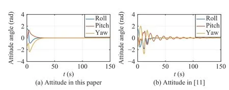
Fig.12.AUV’s attitude under controllers in this paper and in [11].
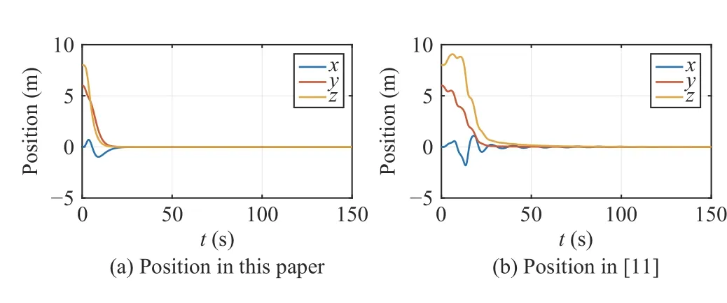
Fig.13.AUV’s position under controllers in this paper and in [11].
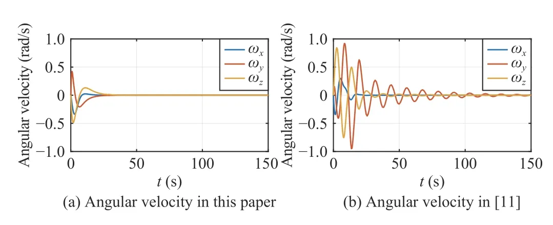
Fig.14.AUV’s angular velocity under controllers in this paper and in [11].
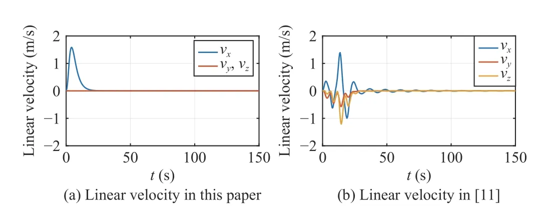
Fig.15.AUV’s linear velocity under controllers in this paper and in [11].
V.CONCLUSIONS
In this paper,we study the problem of the underactuated vehicle’s stabilization under the framework of Lie group SE(3).The kinematics of the underactuated vehicle is considered which features nonholonomic constraints.Additional rotation matrices coupled with translation components are constructed so as to compensate for the lack of sway and heave velocity.We utilize the logarithmic map to design the stabilization controller which makes the closedloop system almost globally exponentially stable.Furthermore,the control law can drive the underactuated vehicle to any specified constant configuration and achieve set-point stabilization.
Future work will focus on the dynamic model of the underactuated vehicle,since it is more common for vehicles to be actuated by force and torque.However,regarding the dynamic model,the system’s state space is notSE(3)anymore,but the tangent bundle of SE(3),where the tangent space is included.Also,the dynamic model includes a drift term caused by gyroscopic force that cannot be compensated by the control in the case of underactuation.This will make the problem more challenging.Another challenge arises from the nonholonomic constraint,which is no longer first-order but second-order,since it is lifted from velocity to force.Thus,the control of the underactuated vehicle’s dynamics by techniques on Lie groups still needs further investigation.
杂志排行
IEEE/CAA Journal of Automatica Sinica的其它文章
- Sampling Methods for Efficient Training of Graph Convolutional Networks:A Survey
- Fault Accommodation for a Class of Nonlinear Uncertain Systems With Event-Triggered Input
- Precise Agriculture:Effective Deep Learning Strategies to Detect Pest Insects
- Maximizing Convergence Speed for Second Order Consensus in Leaderless Multi-Agent Systems
- An Adaptive Rapidly-Exploring Random Tree
- Aerodynamic Effects Compensation on Multi-Rotor UAVs Based on a Neural Network Control Allocation Approach
