Numerical Solution of VLEC Hydrodynamic Response Coupled with Tank Sloshing
2021-12-31-,-
-,-
(Jiangnan Shipyard(Group)Co.,Ltd.,Shanghai 201913,China)
Abstract: The coupling effects of tank sloshing on the ship motion and wave-induced loads of a very large ethane carrier(VLEC)with a loading capacity of 98 000 m3 and four prismatic independent Type B cargo tanks are systematically investigated. The ship motion equation coupled with tank sloshing is calculated in frequency domain based on the three-dimensional linear potential flow theory. The added mass, damping coefficient and restoring stiffness correction due to tank sloshing are fully considered. The response amplitude operators (RAO) of ship motion and sectional loads with and without considering tank sloshing are obtained. Taking the equivalent design wave determined from the maximum RAO of roll as excitation input condition,the three-dimensional fluid sloshing movement behavior and sloshing-induced impact pressure are simulated by the computational fluid dynamics (CFD)method. The renormalized group (RNG) k-ε turbulence model is selected based on the Reynolds-Averaged Navier-Stokes (RANS) equation, and the volume of fluid method is adopted to predict the free surface elevation. The results can provide a valuable reference for the overall design and structural safety assessment of VLEC.
Key words:VLEC;ship motion;tank sloshing;coupling effects;frequency domain analysis;volume of fluid method
0 Introduction
US shale gas development boom prompts significant increase in ethane production,lower prices,as well as marked increase in demands for ethane in Asia and Europe,which in turn brings a lot of transport demands. Ethane carriers gradually become the hotspot of international gas ship market. Historically, ethane has been transported in small liquefied ethane/ethylene carriers designed and constructed to carry ethylene as well as ethane. Almost all the vessels adopt Type C cargo tanks which limit the cargo loading capacity. It is estimated that the maximum feasible size of a ship with Type C cargo tanks is around 40 000 m3based on the design pressure limitation and economic factor. The recent US revolution in ethane production has fuelled a growing demand for far larger, high-capacity ethane carriers. Thus, very large ethane carrier (VLEC) with prismatic independent Type B cargo tanks would play an important role for ethane transport in the near future.The key technology of VLEC is the design and construction of a cargo containment system.
Tank sloshing behavior is of important concern in the design of liquefied gas carriers.Sloshing flow in liquid cargo tanks is firstly excited by ship motion, but the sloshing flow itself affects the ship motion in return.The coexistence of free surfaces inside the tank and outside the hull provides different dynamic loads. The hydrodynamics analysis of a liquid cargo ship has commonly been investigated by ignoring the coupling effects because of its complexity. Recent numerical simulation and experiments have shown that it is only valid when the ship size is much larger than the size of the liquid cargo tank or when the tank is fully loaded.Ships with partially filled liquid tanks are sensitive to tank sloshing in rough sea[1]. Several studies have been carried out to predict the coupling effects between ship motion and tank sloshing until now.In particular,the recent studies can be categorized into two main approaches: the frequency domain approach adopting linear sloshing flow and the time domain approach assuming nonlinear sloshing flow.Molin et al(2002)[2],Malenica et al(2003)[3], Newman (2005)[4]and Huang et al (2009)[5]have studied the coupling effects based on linear potential theory in the frequency domain. The approach is used under the assumption of small amplitude ship and fluid motions.However,issues invariably arise regarding the applicability of linear sloshing flow assumption as the amplitude or intensity increases[6]. To account for the nonlinear effects, simulations in time domain based on computational fluid dynamics (CFD) were conducted by Lee et al(2007)[7],Kim et al(2007)[8],and Mitra et al(2012)[9].In the time domain simulation,the nonlinear viscous damping can be included,the fluid motion inside the liquid tank is not necessarily small. However, very violent fluid motions such as overturning and splash cannot be considered.When the internal fluid motion is mild,impact pressure on the tank wall is extremely difficult to simulate. Model test study is still the main means, Mikelis et al (1984)[10], Francescutto and Contento(1994)[11],Nasar et al (2012)[12]carried out a series of model tests about the coupling effects.In their study, they concluded that the coupling effects do not always result in the increase of sloshing-induced pressure and that the increase or decrease of pressure is dependent on resonant condition.
In general, the coupling effects analysis is still a challenging task. Most of the studies mentioned are about LNG,FPSO and barge.A VLEC with 98 000 m3loading capacity and four prismatic independent Type B tanks is systematically analyzed in the investigation. The main focus is the influence of tank sloshing on the global hydrodynamic response of VLEC, breaking or splash loads on the containment system caused by ship motion with strong nonlinearity are not taken into account. For this purpose, the linear potential theory in the frequency domain is adopted and acceptable with reasonable accuracy. As is well known, the large sloshing fluid movement is prone to create highly-localized impact pressures on the tank wall, particularly when resonant excitation occurs, which in turn causes structural damage. A CFD method is adopted to simulate the three-dimensional fluid sloshing movement behavior and sloshing-induced impact pressure for local strength assessment of independent Type B tank.
1 Mathematical formulation
1.1 Modeling of linear hydrodynamics
Since the entire analysis is linearized,nonlinear sloshing effects are not included.With the assumption of incompressible and inviscid fluid, the perturbation potentialφPis expressed as a sum of the diffraction potentialφDand the radiation potentialφR:

For the internal fluid, the diffraction problem is not solved because no incident wave exists.Only the boundary-value problem and solution of the radiation problem are stated here.
The radiation potentialφRcan be described by the superposition of six basic motion modes with time and space separation:

whereηj(j=1,2,…,6)denotes the complex amplitudes of the body oscillatory motion in its six rigid-body degrees of freedom,φjis the corresponding unit-amplitude radiation potentials, eiωtdenotes the oscillation factor, i is the imaginary unit andωis the encounter frequency, andtdenotes the time.
The boundary value problem for theφjcan be written as:

wheregis gravitational acceleration, the unit vectornis normal to the body boundary and points out of the fluid domain,andris the position vector.
For the internal fluid, the mean free surface has the vertical velocityZ˙0. The velocity potentialφPis added to solve the boundary value problem on the body surface[13].

whereρsis the density of internal fluid.
By introduction of the zero-speed free-surface Green function that satisfies the free surface condition and the radiation condition, the previous boundary value problem can be solved by the well-known boundary integral equation.
1.2 Hydrostatic restoring stiffness correction
The hydrostatic effect of internal fluid is considered as the reduction of restoring force, in particular roll motion[14].
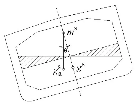
Fig.1 Correction in restoring force due to internal fluid

whereWis weight of the ship,wSis weight of the internal fluid,ISis 2nd rotational inertia moment of the internal free surface,VSis volume of the internal fluid.
Eq.(7)represents the restoring stiffness correctionKSdue to sloshing fluid as follows:

Therefore,KSis only related toISandρS,and not affected by filling level or location of tanks.
1.3 Ship motion equation coupled with tank sloshing

The hydrodynamic coefficients such as added massMaand potential dampingCcan be obtained through the following equations:

whereSBindicates the mean wet surface of the body,jandkmean the motion modes.

Only the inertia force of sloshing fluid is considered, since there is no radiation damping for the internal problem within the potential theory.Sloshing forceFS(ω)is given by:

whereMas(ω)is added mass of sloshing fluid.

whereγis a ratio to the critical roll damping and depends on the ship characteristic. For VLEC,γis 0.04 compared with conventional ship in a range of 0.02-0.05.
Eq.(14)and Eq.(15)are merged into the following equation:

Based on the theories mentioned above, the analysis of coupling effects between ship motion and tank sloshing can be carried out.
2 Hydrodynamic model
The global hydrodynamic response analysis is performed for a system consisting of a panel model and a mass model. To calculate the inner tank hydrodynamics, tank definition shall be included in the panel model.The panel model representing VLEC outer hull and four prismatic independent Type B tanks is shown in Fig.2.It is of importance that the mesh density reflects the hydrodynamic pressure variation around the structure. In tanks where the pressure variation is large, the tanks are modeled with a considerably fine mesh.
The mass model for the sectional load calculation is shown in Fig.3. The mass is simply modeled as transverse beams and point masses representing mass distribution,thereby ensuring that the roll radius of gyration and metacentric heights are correct. Moreover, tank fluid shall be excluded from the mass model,since it is represented by the added mass from the internal radiation problem.

Fig.2 Panel model

Fig.3 Mass model
3 Simulation results
3.1 Roll added mass and radiation damping
The added mass and radiation damping of sloshing fluid in tanks at three different filling levels(30%,50%and 70%)are calculated as shown in Figs.4-5.Roll added massA44 is non-dimensionalized byρVL2and roll radiation dampingD44 is non-dimensionalized byρVL gL,Vis displaced volume of panel model,Lis ship length.

Fig.4 Roll added mass of sloshing fluid

Fig.5 Roll radiation damping of sloshing fluid
To get a better understanding of the characteristics of sloshing resonance, the natural sloshing frequencies are determined. The natural transverse sloshing frequenciesωr,nin different surface modes for a rectangular tank are calculated through the linear approximation equation[15]:

whereBTdenotes the transverse sloshing breadth,hindicates the filling depth of tank,nrepresents the surface mode number.
For a prismatic tank with chamfered bottom, Faltinsen and Timokha (2009)[16]proposed a correction factor:

For a typical tank, the main parameters are: length 39.6 m, width 34.4 m, and height 18.8 m, and the first mode sloshing frequency at different filling levels are shown in Tab.1.
The results show that the peak frequency of roll hydrodynamic coefficients is well consistent with the transverse sloshing resonance frequency. Roll hydrodynamic coefficients vary with the filling level changing especially,and reach its maximum exactly at the first sloshing resonance frequency.Away from sloshing resonance frequency,roll hydrodynamic coefficients decrease significantly.
3.2 Ship motion and sectional load
For simplicity of analysis, 30% and 70% filling levels are considered and all partially-filled tanks are filled at the same filling level. Both numerical simulations considering and ignoring tanksloshing are conducted by the radiation-diffraction panel code WADAM.

Tab.1 The first mode natural transverse sloshing frequencies
Figs.6-8 show the effects of tank sloshing on three main ship motion at 30%and 70%filling levels. An insignificant effect of tank sloshing on pitch and heave motion was observed in heading sea condition as shown in Figs.6-7.Roll motion amplitude tends to decrease as filling level increases and the single peak of roll RAO is split into two separated smaller peaks as shown in Fig.8. The phenomenon of great interest is that the two peaks do not exactly appear at the roll natural frequency and the first mode tank sloshing frequency. The first peak is the roll natural frequency which is shifted towards a lower frequency due to the reduction of roll restoring stiffness caused by external fluid dynamic. The second peak induced by sloshing dynamics is shifted toward higher frequency than the first mode tank sloshing frequency.
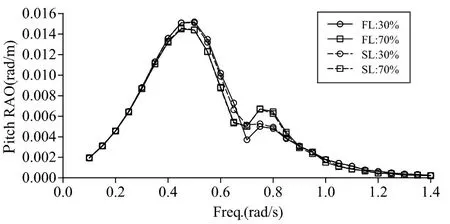
Fig.6 Pitch RAO in heading sea
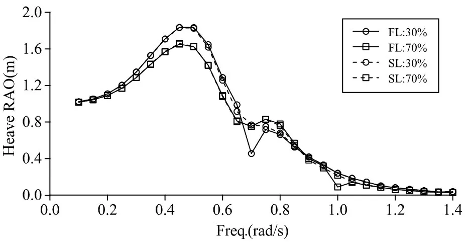
Fig.7 Heave RAO in heading sea

Fig.8 Roll RAO in beam sea
Taking 70% filling level for example, the sloshing-induced peak can be observed at the frequency of 0.95 rad/s,which is 11.8%larger than the first mode tank sloshing frequency of 0.85 rad/s.Meanwhile, the sloshing-induced peak in roll motion shifts towards higher frequency as the filling levels increase. It can be explained through that the first mode sloshing frequency becomes bigger as the filling levels increase. Similar observation has also been reported by Bunnik et al (2010)[17]and Zhao et al (2014)[18].Roll motion coupled with tank sloshing appreciably changes with the excitation frequency. Taking 30% filling level for example, roll motion is relatively small in a certain frequency range of 0.40-0.75 rad/s, and reaches the minimum at 0.56 rad/s, then the partiallyfilled tank acts as an anti-rolling tank.
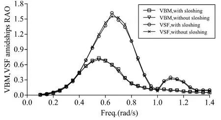
Fig.9 VBM and VSF amidships RAO in heading sea

Fig.10 TM amidships RAO in beam sea
Additionally, hydrodynamic loads of VLEC at 30% tank filling level under regular wave are calculated.Figs.9-10 represent that the comparison of three different sectional loads RAO at amidships with and without considering tank sloshing, such as vertical bending moment(VBM),torsional moment (TM) and vertical shear force (VSF). The wave-induced moment and force are non-dimensionalized byρVgWaandρVgWa/L,respectively.Wais wave amplitude of the incident wave.
For heading sea condition,VBM and VSF show no significant deviations whether tank sloshing is considered or not,from which it can be inferred that the effects of tank sloshing on the global longitudinal loads will be less significant since the dynamic effect of sloshing liquid motion is much smaller than the longitudinal inertia effect of hull. It is concluded that the effects of tank sloshing on the VLEC hull girder strength assessment can usually be neglected. However, for TM in beam sea condition, the single peak RAO curve of TM transforms to the multiple peak form due to tank sloshing and several significant increased peaks can be observed.
3.3 Sloshing-induced impact pressure
Sloshing-induced impact pressure is critical for the design of cargo containment system.Based on the previous ship motion calculation, tank sloshing undergoing large amplitude roll motion in beam regular waves at 30%filling level is simulated and discussed in the present study.
LR (2004)[19]gave the formulae to determine the approximate maximum‘lifetime’ship motions.The ship’s natural roll periodSnrand the maximum‘lifetime’roll angleφmaxare given by:

whererdenotes the radius of gyration of roll,GMpresents transverse metacentric height with free surface correction,Bdenotes ship breadth. For VLEC, eitherrorGMvaries significantly between loading conditions.
As for the long-term prediction, the wave statistics model is given through the North Atlantic wave scatter diagram. The Pierson-Moskowitz spectrum is assigned to simulate the sea state conditions and the‘cosine squared’spreading is applied to model the short-crested waves.The long-term prediction of roll motion with heading 90° and all wave directions included at each exceedance probability levels are shown in Fig.11.
The results show that the maximum‘20 years’roll motion calculated by LR rule is equivalent to the long-term response extreme value in beam wave condition at the exceedance probability level of 10-8.However,considering all the wave directions,the long-term probability level of roll increases to 10-9.

Fig.11 Long-term prediction of roll motion

Tab.2 Roll motion calculated value
The maximum‘lifetime’roll angle formula given by LR rule is only related to ship breadth and length,which does not consider the sloshing effect.It can be concluded that the maximum‘lifetime’roll angle of VLEC calculated by LR rule is in general over-predicted without including the coupling effects, and the natrual roll period calculated by LR rule is lower compared with that obtained by the numerical calculation method.
The wave frequency, heading and phase of the equivalent design wave are determined from the maximum RAO for roll.The long-term prediction extreme value is taken as the excitation input and the roll oscillation center is located in the center of gravity.A general-purpose CFD code FLOW-3D is adopted to simulate the three-dimensional fluid sloshing movement behavior and sloshing-induced impact pressure.The tank CFD model is shown in Fig.12.A proper definition of the boundary conditions at the free surface is important for an accurate capture of the free-surface dynamics. The volume of fluid method (VOF) is adopted to predict the free surface elevation. Incompressible viscosity flow is considered and renormalized group(RNG)k-εturbulence model is selected based on the Reynolds-Averaged Navier-Stokes (RANS)equation.Implicit solver method is used to do the numerical calculation.
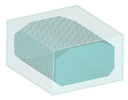
Fig.12 Tank CFD model
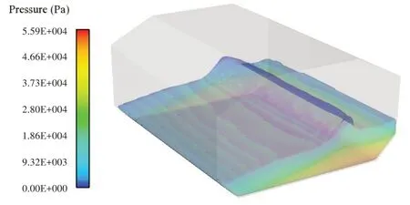
Fig.13 Free surface and pressure distribution at t=13.5 s

Fig.14 Free surface and pressure distribution at t=14.3 s
As the tank oscillates at 30% filling level,three categories of sloshing phenomena and obvious free surface can be observed in Figs.13-14.A standing wave is formed when the excitation frequency is far below the sloshing natural frequency. As the frequency increases, a series of progressive travelling waves with a very short wavelength appear.A hydraulic jump is formed due to a small disturbance at a range of frequency around the sloshing resonance frequency.Since the hydraulic jump has high kinetic energy, it produces a higher impact pressure on the tank wall, which increases the risk of structure damage.
4 Conclusions
The coupling effects of tank sloshing on VLEC motion and sectional loads are numerically simulated by the linear frequency domain approach. The application of this approach is practical and efficient in evaluating the simplified coupling problem. A CFD method is adopted to simulate the three-dimensional fluid sloshing movement behavior and sloshing induced impact pressure. Based on the present investigation,the following conclusions can be drawn:
(1)The effects of tank sloshing on heave and pitch motion in heading sea condition are insignificant compared with those on roll motion. Both heave and pitch motion show no dependency on the tank filling level.
(2)Tank sloshing would either increase or reduce roll motion,which depends on the first mode transverse frequency of tank sloshing and the roll natural frequency of VLEC. Roll motion can be significantly reduced by tank sloshing when the excitation frequency is close to the first mode sloshing frequency.
(3) Instead of one single high resonance peak, roll RAO coupled with tank sloshing presents two smaller peaks,whose position and magnitude are sensitive to the tank filling level.
(4)For hull girder loads,torsional moment is more sensitive to tank sloshing than vertical bending moment and shear force. It indicates that tank sloshing can usually be neglected in the global longitudinal strength assessment of VLEC except in the torsional strength assessment.
(5) High impact pressures on the tank wall could be induced by hydraulic jump sloshing waves,especially at low filling levels.
The conclusions can provide valuable reference for the development of VLEC. The validity of the results discussed here clearly requires more detailed investigations.Future study is also needed to focus on the nonlinearity coupling effects and model test.
杂志排行
船舶力学的其它文章
- Responses of Large-ship Mooring Forces Based on Actual Measurement
- Experimental Study on Fatigue Crack Growth of Compact Tensile Specimens Under Two-Step Variable Amplitude Loads with Different Cyclic Ratios
- Study on Influence Law of System Parameters on the Dynamic Response of High-static-low-dynamic Stiffness Vibration Isolator Working Under Off-design Condition
- Bivariate Kernel Density Estimation for Meta-ocean Contour Lines of Extreme Sea States
- Study on the Tip Vortex Control Effect and Rule of Pump Jet Thruster by Groove Structure
- On Scale Effect of Open Water Performance of Puller Podded Propulsors Based on RANS
