Effect of Connection System on Side-by-side System of FLNG and LNGC
2021-12-31-,-,,-,-,
-,-,,-,-,
(1.School of Naval Architecture,Dalian University of Technology,Dalian 116024,China;2.Offshore Oil Engineering Co.,Ltd.,Tianjin 300461,China)
Abstract: For the new technical concept of floating liquefied natural gas production, storage and offloading system (FLNG), in order to solve the interactive hydrodynamic problem and study the dynamic responses of connection system in side-by-side offloading operation of FLNG and LNGC, this paper presents the time-domain numerical method considering the coupling effect of FLNG-LNGC vessels and vessel-mooring systems. By comparison of the experimental motion responses of two vessels,the accuracy of the numerical method in the paper can be verified.Finally,the various test cases with different layout schemes, pretension and stiffness of connection hawsers are investigated, and their sensitive effects and contributions on the relative motions of offloading arms and mooring force on connection systems are also studied in detail. Through the researches, the no-cross layout scheme can make the relative motion between FLNG and LNGC more stable and should be applied in the practical engineering. Furthermore, in spite that the increase of hawser pretension and stiffness can restrain the relative motion, it can also reduce the safety factor of connected hawsers, which decides the optimal and reasonable design of the hawser pretension and stiffness.
Key words:side-by-side offloading problem;time-domain numerical method;interactive hydrodynamic performance;connection system;relative motion;mooring force
0 Introduction
With the development of natural gas gradually extending to remote and marginal gas fields[1],the traditional method of gas exploitation through the subsea pipeline has become difficult and uneconomical for deep sea exploitation. Therefore, FLNG[2], which includes LNG storage tanks in vessel and functional modules (liquefaction, purification, etc.) on deck, has been presented and should become an important concept for deep-water gas development[3]due to its large capacity, strong adaptability and convenience,etc..
In the side-by-side offloading operation of an FLNG and an LNG,the distance between two vessels is small, thus the offloading system should present complicated hydrodynamic performance due to the coupling interactions,which may cause damage of the offloading arm or breaking of the connection system. Thus, the accurate numerical simulation on the relative motion of FLNG-LNGC and mooring force to ensure the security during offloading operations is important and challenging.In frequency domain, Kodan (1984)[4]studied the hydrodynamic interactions of parallel floating bodies based on the 2D wave potential theory.Buchner et al(2001)[5]analyzed the motion responses of FLNG and LNGC by considering the cross-coupling effects between two bodies.Choi and Hong(2002)[6]predicted the interactions of multi-body systems by 3D boundary element method.Hong et al(2005)and Kashiwagi et al(2005)[7-8]investigated the motion responses and wave drift forces of a multi-body system by introducing the viscous rolling damping.On the other hand,it is acknowledged that the timedomain analysis can consider the more complex nonlinear coupling effects of multi-body and mooring system. Therefore, some recent researches are concerning the time-domain simulation. Therein, Inoue and Kamruzzaman(2005)[9]studied the wave forces by 3D sink-source technique in time domain.Koo and Kim (2006)[10]took the time-domain simulation of a multi-body system with dynamic coupling effects of vessels and mooring systems.Naciri(2007)[11]evaluated a time-domain analysis of the side-by-side moored vessels and compared with model tests. Zhao (2012, 2013, and 2014)[12-14]executed a time-domain analysis to numerically simulate the motion responses through model tests. Li(2020)[15],Tang(2021)[16]and Bai(2021)[17]studied the hydrodynamic resonance and shielding effect of side-by-side multi-bodies. Although the motion responses of FLNG and LNGC have been studied,the coupling interaction and the existing data in time domain (such as the relative motions of the LNG offloading arm,the mooring tensions,fender forces and so on)are still far away from adequacy to accurately predict the characteristics of FLNG-LNGC and ensure the safety of offloading operation in the complex and actual sea states.
In this study,the hydrodynamic models of the FLNG vessel and LNG carrier based on wave potential theory in time domain is presented by considering the comprehensive coupling interaction of two vessels, hulls-turret system, and hulls-connection system. The numerical method is validated by a series of model tests. Sensitivity studies about layout scheme, pretension and stiffness of hawsers are investigated,and the relative motions of offloading arms and mooring forces of connection systems are analyzed,providing an efficient guidance for the offloading scheme.
1 Numerical model and time-domain method
Here a multi-body system of FLNG and LNGC described by Zhao (2014)[14]was chosen as test case of this paper.
1.1 Parameters of the side-by-side FLNG-LNGC system
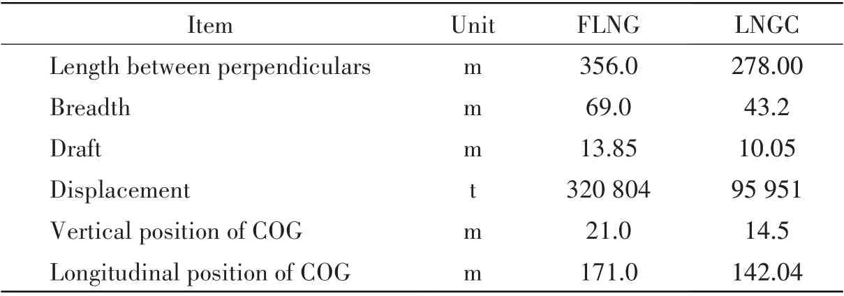
FLNG and LNGC are arranged side by side and positioned by an external turret in the 1 500 m water depth.The hydrodynamic models and main parameters of FLNG and LNGC can be described in Fig.1 and Tab.1 respectively.

Fig.1 Hydrodynamic models of FLNG-LNGC
Tab.1 Main parameters of FLNG vessel and LNG carrier
The external turret connects with 12 mooring lines divided into 3 groups.Therein,one group consists of 4 mooring lines with 5°interval angle as shown in Fig.2.Each mooring line has an overall length of 6 100 m,three segments as chain-wire-chain,and a horizontal span of 5 850 m.Furthermore,the connected system between FLNG and LNGC in the offloading operation includes eight hawsers(1#-8#)and four fenders(1#-4#)as shown in Fig.2.
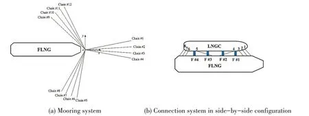
Fig.2 Sketch of mooring and connection systems
1.2 Wave loads on two vessels
Wave potential theory is used to solve the hydrodynamic parameters of two vessels. Firstly, the total velocity potential can be divided into three parts and satisfy the Laplace equation in the fluid domain and boundary conditions.

whereφ0is the velocity potential of incident wave,φ7is the diffraction potential,φj(j=1,2,…,6) is the radiation potentials, andωis wave frequency. For the radiation problem of two interactive vessels,the velocity potentialsΦ(a)andΦ(b)near FLNG vessel(a)and LNG carrier(b)can be expressed as,

Furthermore, in order to solve the problem of numerical oscillation during the side-by-side offloading operation, the artificial viscous damping should be introduced on the free surface between two vessels[18],

whereμis artificial damping coefficient.By calculating the boundary integral equation,the total velocity potential can be obtained. Then, first-order hydrodynamic pressure can be obtained from the Bernoulli’s equation.Sequentially the first-order wave force can be integrated along the wetted surface.

where wave excitation force in regular wave includes incident forcef0kand diffraction forcef7k.Tkjis radiation force inkdirection corresponding tojfreedom motion with unit speed. Furthermore, the wave force,retardation function and added mass in time domain can be described as follows.

1.3 Time-domain coupled analysis equation
In order to handle the nonlinear coupling effects of two vessels and mooring systems, the motion equations of the multi-body system in side-by-side configuration in time domain are written as[19-20],

where superscript (a) and (b) denote FLNG vessel and LNG carrier respectively,x¨,x˙andxare the acceleration, velocity and displacement vectors,Mis the generalized mass matrix,m(∞) is the added mass of infinite frequency, andRis the retardation function matrix. It should be noted that the interaction on frequency-dependent added mass and damping forces are included in coupled added mass and retardation functions at infinite frequency.Bis the damping matrix,Kis the hydrostatic stiffness coefficient,FEis the first-order wave excitation force (moment), andFSVis the second-order slowly-varying force (moment).FWandFCdenote the wind force and current force.FMandFconare the mooring forces of turret and connected system restricting the motion response of floating body in the horizontal plane,which are calculated by the dynamic models of composite catenary cables,linear and nonlinear elastic cables[21-22]due to the elongation of mooring systems.
1.4 Validation of time-domain method of this paper
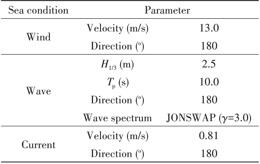
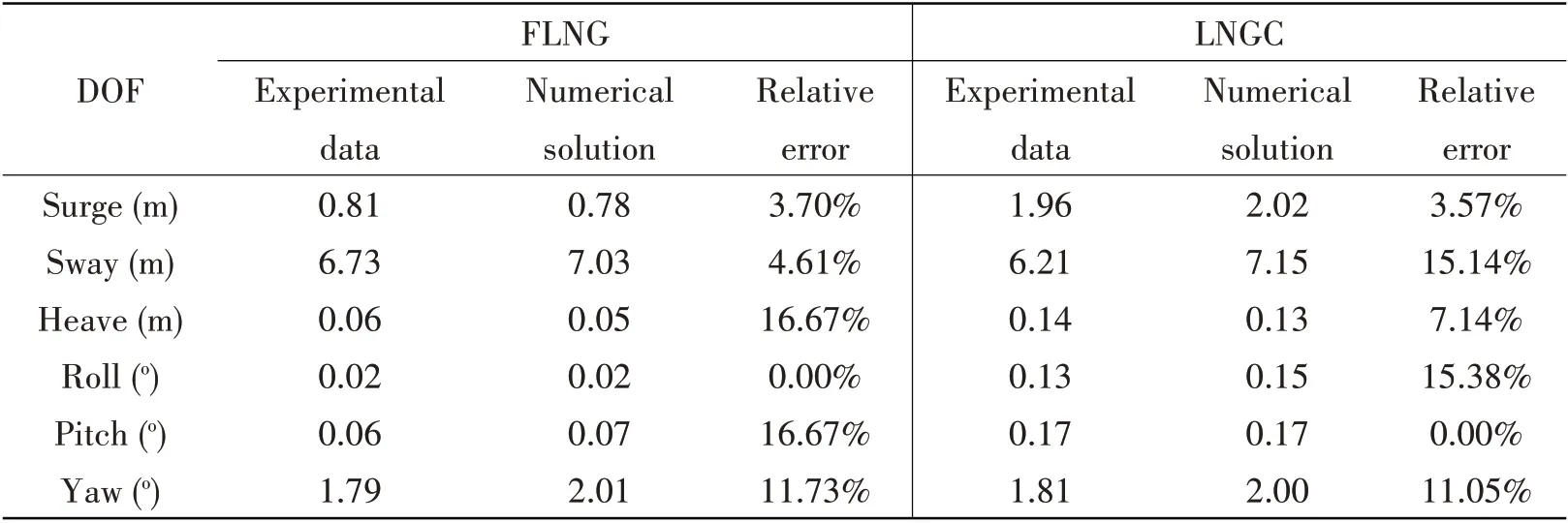
The sea state with the same direction of wind,current and wave is taken for test case as shown in Fig.3 and Tab.2. By means of numerical method of this paper, the spectra of motion responses can be analyzed and plotted in Fig.4 along with experimental data[14]. Then the standard deviations of 6 DOF motions of the FLNG and LNGC versus numerical and experimental methods can be further calculated and listed in Tab.3.
Tab.2 Environmental conditions for sea condition
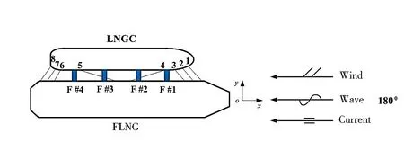
Fig.3 Sketch of the sea condition
Tab.3 Standard deviations by experimental data and numerical method
From Fig.4 and Tab.3, it can be found that motion responses of FLNG and LNGC by the numerical method are in good agreement with experiments[14],which validates the reliability and practicability of the numerical method.
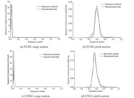
Fig.4 Spectra of motion responses of FLNG and LNGC
2 Effect of connection system on the side-by-side system
Based on the numerical method of this paper, the various cases with different layout schemes,pretension and stiffness of connected hawsers are investigated,and their sensitive effects on the relative motions of offloading arms and the force on connection system are also studied.Firstly,the positions of offloading arms 1#~3# are shown in Fig.5. Coordinates of connected points on FLNG and LNGC of three offloading arms are listed in Tab.4.

Fig.5 Arrangement sketch of three offloading arms

Tab.4 Coordinates of connecting points for offloading arms
2.1 Layout schemes of connected system
Here four hydrodynamic models of FLNG and LNGC in the side by side configuration under sea condition in Tab.2 with different layout schemes of hawsers and same pretension 450 kN, EA 3 375 kN are plotted in Fig.6.
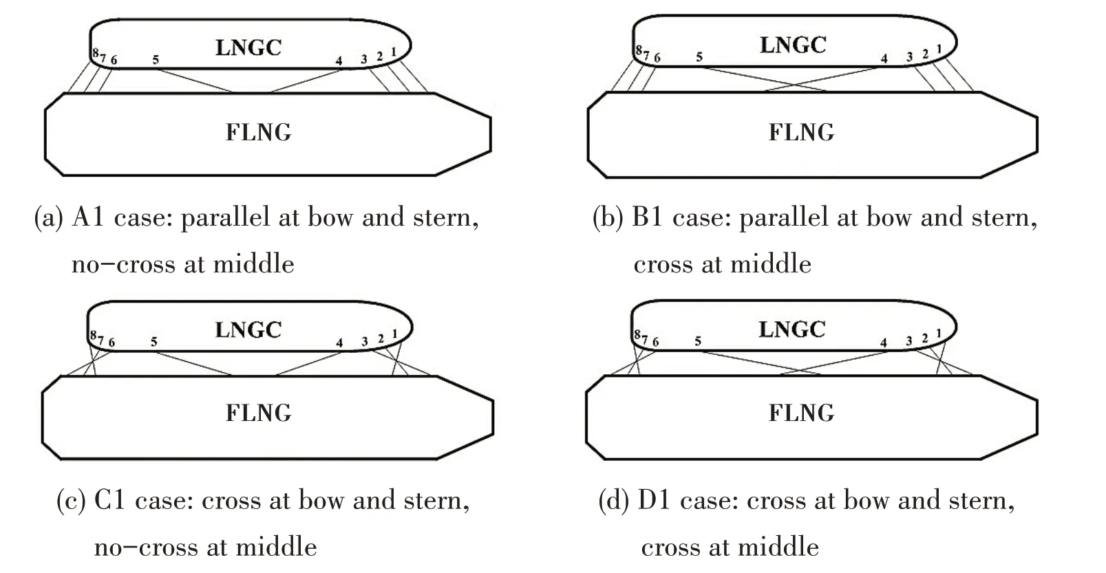
Fig.6 Four layout schemes of connected system
2.1.1 Influence of layout scheme on the relative motion
Based on the four layout schemes of A1, B1, C1 and D1, the effects of layout schemes of hawsers on the relative motion between FLNG and LNGC are considered.Here the offloading arm 2#is taken for example,time histories of the relative motion responses of two connection points on FLNG and LNGC versus different layout scheme are described in Fig.7. From the figure, it is shown that the relative motion response of the offloading arm inxdirection can mainly present low frequency and ultra-low frequency components which may result from the surge and yaw motions of FLNG and LNGC, and then the curves ofy-directional relative motion have three characteristics of wave frequency, low frequency and ultra-low frequency which depend on the roll, sway and yaw motions of FLNG and LNGC respectively. Furthermore, time histories ofz-directional relative motion can only display the periodic vibration with wave frequency caused by the heave,roll and pitch motions.

Fig.7 Relative motion responses of offloading arm#2 in different cases of layout schemes
On this basis, the statistics of the relative motion responses of 1#~3# offloading arms are analyzed and listed in Tab.5.By comparing with theyandzdirections,under the sea condition various layout schemes have a large influence on thex-directional relative motion responses. Among the four layout schemes,the mean and standard deviation ofx-directional relative motion for A1 case is minimum and those for the C1 and D1 cases are relatively larger,which shows the layout scheme of A1 case can make the relative motion between FLNG and LNGC more stable under the same sea condition. Therefore, the layout scheme A1 is more feasible in the practical engineering. Furthermore, by comparing the statistical data of the 1#~3# offloading arms, it can be found that the distinction ofx-directional relative motions versus different offloading arms is very small. However,there are apparent differences on theyandzdirectional motions.Therein,the standard deviation of relative motion response versus the 2#is the least and that versus the 1#is the most.Therefore,the practical offloading arm should be arranged near the middle of FLNG and as far away from the bow and stern as possible.

Tab.5 Statistics of relative motion of offloading arms in different cases of layout schemes
2.1.2 Influence of layout scheme on the connected system
Based on the four cases, the maximum tensions of hawsers versus different arrangements are numerically simulated and demonstrated in Tab.6. From the aspect of safety, the calculated hawser tensions of four schemes in Tab.6 are all less than the safe working load of 796.95 kN and thus can satisfy the security requirement. Furthermore, it can be found that the wave loads on the connected system of case A1 can be more evenly distributed on each hawser from 1# to 8# hawser. Thus, the standard deviation and maximum tension for case A1 are the smallest,which shows that the scheme A1 is most reasonable. Finally, the relative deviation between A1 and C1 cases can be up to 11.78%, which shows that the layout scheme of hawser has a certain influence on the hawser tension.
The maximum force on the fenders versus four different layout schemes can be obtained in Tab.7. In the table, the forces on the four fenders are far less than the safe working load of 3 000 kN, and thus the fender forces can meet the safety requirement. Furthermore, there is little difference of maximum fender forces for four different schemes.

Tab.6 Maximum hawser tensions in different cases of layout schemes

Tab.7 Maximum fender forces in different cases of layout schemes
2.2 Pretension of connected hawsers
In order to discuss the effect of hawser pretension on the hydrodynamic performance of FLNG and LNGC systems,four different initial pretensions can be selected in Tab.8.

Tab.8 Cases with different hawser pretension
2.2.1 Influence of hawser pretension on the relative motion
Time histories of relative motion responses between two end points of 2#offloading arm versus four cases of different pretensions can be obtained and shown in Fig.8.Furthermore,the statistics of the relative motion between the connected points of FLNG and LNGC of 1#~3#offloading arms versus four cases of different pretensions are analyzed and obtained. From the figures, it can be found that the smaller the hawser pretensions, the weaker the constraint effects of connected system on the relative horizontal motion of FLNG and LNGC, which will cause the relative motion response of offloading arms to present more distinct low-frequency characteristics.


Fig.8 Relative motion responses of offloading arms#2 in four cases of different pretension
For the convenience of quantitative analysis, the statistical data of relative motion responses can be achieved and listed in Tab.9.As shown in table,when the pretension is less than 450 kN,especially from 300 kN to 150 kN, the mean and standard deviation ofx-directional relative motion can increase nonlinearly with the linear decrease of pretension.On the other hand,if the pretension is larger than 450 kN,the averagex-directional relative motion response becomes gradually greater but the standard deviations are more or less the same.Thus,the larger the hawser pretension in the initial stage is, the weaker the relative motion is. But after the pretension increases to a certain extent, the effect of pretension on the relative motion becomes very small, which shows that there should be a most suitable pretension to make the relative motion of FLNG and LNGC minimum.Furthermore,they-directional relative motion demonstrates the similar performance as thex-direction,yet the hawser pretension has little effect on the heave relative motion.The reason may be that thexdirectional relative motion responses mainly result from the surge and yaw motions,they-directional results are mainly caused by the yaw,sway and roll motions,and thez-directional results depend on the heave,pitch and roll motions.The connected system is basically applied to the positioning in the horizontal plane,and thus has marked influence only on the restriction of horizontal motions.
By comparing the relative motion responses of#1~#3 offloading arms versus four pretensions,it can be found that there is a more sharp distinction onz-directional relative motion responses.Therein,the relative motion of the offloading arm is the least in the middle and is the most near the bow.

Tab.9 Statistics of relative motion of offloading arms in different pretension cases
2.2.2 Influence of hawser pretension on connected system
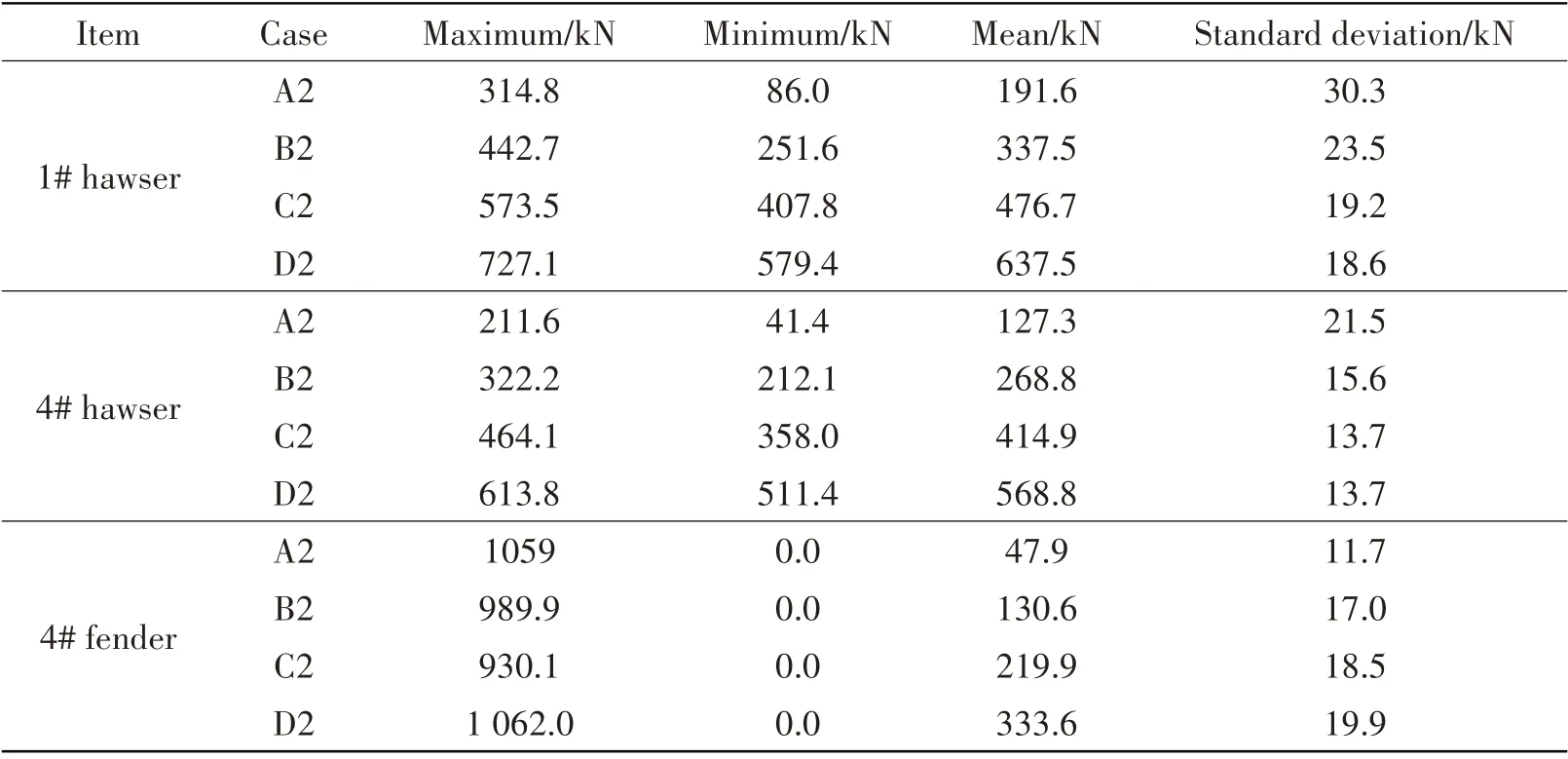
Based on the numerical method, time histories of the forces on the 1#, 4# connected hawsers and 4# fender are shown in Figs.9-10. Furthermore, the corresponding statistics on the connected system are listed in Tab.10.

Fig.9 Time histories of the hawsers tension between FLNG and LNGC

Fig.10 Time histories of the forces on fender#4 in four cases of different pretensions
Fig.9 shows the tensions of the 1# and 4# hawsers under different pretensions. In the figure,the hawser tensions periodically vibrate around the average value which gradually enlarges with the increase of pretension.By further combining with Tab.10,it can be seen that the larger the linearity of the hawser pretension, the smaller the nonlinearity of the standard deviation of hawser tension.Then the standard deviation of D2 case can be further found to be close to that of the C2 case,which shows the variation of hawser pretension tends to be basically stable.Moreover,with the hawser pretension increasing, the maximum hawser tension becomes larger. Therein, the max tension correspondsing to the 1# hawser is 727.1 kN, which is close to the safe working load of 796.95 kN for this kind of wire rope. Therefore, despite that the increase of hawser pretension can restrain the relative motion of FLNG and LNGC,it can also reduce safety factor of connected hawsers,which decides the reasonable design of the hawser pretension according to the minimum breaking load of connected hawsers.
Finally, Fig.10 shows the time histories of 4# fender versus various pretensions. From the figure,the smaller the hawser pretension,the shorter the contact time between the fender and the hull,the more obvious the pulse characteristics of fender force. Furthermore, based on Tab.10, it can be found that the max fender forces under four cases have no big difference versus four cases of different pretensions. But the mean fender force gradually enlarges with the increase of the hawser pretension.
Tab.10 Statistics of hawses and fenders in different cases of pretension
2.3 Stiffness of connected hawsers
In order to discuss the effect of hawser stiffness on the hydrodynamic performance of FLNG and LNGC,four cases with different hawser stiffness are shown in Tab.11.

Tab.11 Cases with different hawser stiffness
2.3.1 Influence of hawser stiffness on the relative motion
Time histories of the relative motion of two connection points of 2# offloading arms on FLNG and LNGC versus four cases of different stiffness are calculated and shown in Fig.11. Furthermore,the relative motion responses of 1#~3#offloading arms between FLNG and LNGC versus four cases are statistically analyzed and listed in Tab.12. By combining Fig.11 with Tab.12, it can be found that under the sea condition thex-directional relative motion responses of offloading arms are quite sensitive to hawser stiffness. Especially if the hawser stiffness is small, thex-directional relative motion of offloading arm becomes violent. When the hawser stiffness decrease from 3 375 kN to 945 kN, the mean and standard deviation ofx-directional relative motion responses has a more marked change. Under the condition of heading sea, hawser stiffness has a slight influence on theyandzdirectional relative motion.
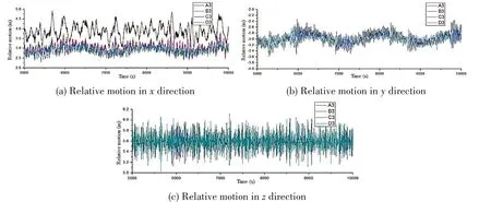
Fig.11 Relative motion response of offloading arms#2 in different cases of stiffness

Tab.12 Relative motion statistics of offloading arms in different stiffness cases
2.3.2 Influence of hawser stiffness on connected system

Fig.12 Time history of the hawser tensions between FLNG and LNGC

Fig.13 Time histories of the forces on fender#1 in different cases of stiffness
Time histories of the forces on the 1#, 4# connected hawsers and the 1# fender are shown in Figs.12-13. Furthermore, the statistical data of the force of hawser and fender are described in Tab.13. In the figures, it can be seen that with the hawser stiffness gradually decreasing, the lowfrequency component of hawser tension appears more obvious. Moreover, the fender forces are less affected by the variation of hawser stiffness.From the table,the average tensions of connected hawser are close to the pretension and are hardly affected by the stiffness.But the standard deviation of hawser tensions becomes larger with the increase of stiffness.

Tab.13 Statistical data of the force on hawses and fenders in different cases of stiffness
3 Conclusions
Based on the time-domain analysis theory, the coupling interactions of FLNG-LNGC, vesselturret mooring system and vessel-connection system are considered in this paper. Furthermore, the effects of the layout scheme, pretension and stiffness of connected system are mainly discussed in order to seek the effective measure to improve the safety of FLNG-LNGC offloading operation.Some useful conclusions can be made as follows:
(1) By comparing with experimental data, the coupling hydrodynamic model and time-domain numerical method in this paper to simulate the performance of FLNG and LNGC in side-by-side offloading operation are validated to be accurate and feasible.
(2) The connected system is basically applied in the positioning in the horizontal plane, and thus thez-directional relative motions are hardly affected. On the other hand, the layout scheme,pretension and stiffness of connected system can affect thexandydirectional relative motion of the LNG offloading arm, hawser tension and fender force to a certain extent, to which enough attention should be paid in practical engineering of offloading operation.
(3) The no-cross layout scheme of A1 case can make the relative motion between FLNG and LNGC more stable and should be applied in the practical engineering. With the hawser pretension reducing, the contact time between fender and hull should be fewer and the impulse characteristics of fender force should be more obvious. Furthermore, while the increase of hawser pretension and stiffness can restrain the relative motion of FLNG and LNGC, it can also reduce the safety factor of connected hawsers, which decides that the hawser pretension and stiffness have the optimum value and should be reasonably designed.
(4)Under the same working condition,the relative motion of an offloading arm in the middle is the least and at the bow or stern is the most. Thus, the arrangement of an offloading arm should be close to the middle and away from ship bow and stern in the practical engineering of FLNG-LNGC offloading operation.
Acknowledgement
The authors are grateful to all the organizations that have funded the research in this paper,which was financially supported by the Research Project of Marine Engineering Equipment in the Ministry of Industry and Information Technology ([2014]500); Dalian Science and Technology Major Project (2019ZD12GX002);Collaborative Innovation Center of Major Machine Manufacturing in Liaoning.
杂志排行
船舶力学的其它文章
- Responses of Large-ship Mooring Forces Based on Actual Measurement
- Experimental Study on Fatigue Crack Growth of Compact Tensile Specimens Under Two-Step Variable Amplitude Loads with Different Cyclic Ratios
- Study on Influence Law of System Parameters on the Dynamic Response of High-static-low-dynamic Stiffness Vibration Isolator Working Under Off-design Condition
- Bivariate Kernel Density Estimation for Meta-ocean Contour Lines of Extreme Sea States
- Study on the Tip Vortex Control Effect and Rule of Pump Jet Thruster by Groove Structure
- On Scale Effect of Open Water Performance of Puller Podded Propulsors Based on RANS
