Microstructure evolution and mechanical anisotropy of M50 steel ball bearing rings during multi-stage hot forging
2021-10-25HongweiJIANGYnrnSONGYuchengWUDeinSHANYingyingZONG
Hongwei JIANG ,Ynrn SONG ,Yucheng WU ,Dein SHAN ,Yingying ZONG,*
a National Key Laboratory for Precision Hot Processing of Metals,Harbin Institute of Technology,Harbin 150001,China
b AECC Harbin Bearing Co.,Ltd,Harbin 150070,China
KEYWORDS Bearing ring;Flow lines;Forging;Mechanical anisotropy;Microstructure evolution
Abstract This study aimed to explore the evolution of flow lines and microstructures of M50-steel bearing ring and the anisotropy of its tensile mechanical properties after Multi-Stage Hot Forging(MSHF)and subsequent spheroidizing annealing(MSHFA).To this end,the present study mainly employed stereo microscopy,Optical Metallurgical Microscopy(OMM),Scanning Electron Microscopy (SEM),and Electron Backscatter Diffraction (EBSD) to characterize and analyze the workpiece at each processing stage of MSHF while performing microhardness measurement and uniaxial tensile experiment to test and analyze the mechanical properties of the workpiece.Macro-structure observation showed that the simulation results of flow lines at each stage were consistent with the experimental results.Microscopic observation showed that,after MSHF,deformation gradually became less significant along the outward radial direction of the bearing ring.After MSHFA,the microstructures of the bearing ring became uniform,whereas primary carbides did not dissolve.The mechanical properties were better in the axial direction (AD) than in the radial (RD) and circumferential directions (CD) after MSHF due to the smaller grain width.After MSHFA,the mechanical properties in the ADs and CDs were better than those in the RDs,which was due to the large cross-sectional area of carbides along the flow-line direction.
1.Introduction
Aeroengine bearings are required to operate at 300–350°C.M50 high-temperature bearing steel has been widely used to satisfy this requirement.1,2M50 is a fully hardened martensitic steel commonly used in aeroengine bearings,as it has excellent wear resistance,dimensional stability,and high Vickers hardness of 800 even at 300°C.3The excellent properties of M50 are related to its alloying elements and carbides,4,5but M50 has poor hot-working plasticity with high susceptibility to forging defects due to the high content of alloying elements.Hence,the plastic deformation of M50 can only be achieved in a narrow hot-working range.In addition,high-content alloying elements can result in a large amount of primary carbides during solidification.Although primary carbides can increase the hardness and wear resistance of M50,they are usually large in size and irregular in shape,which degrades the continuity of the steel;consequently,the surrounding matrix is prone to cracks under stressed conditions,reducing the processability and applicability.In the forging process,primary carbides will be distributed along the deformation direction in a fibrous pattern and manifest as macroscopic flow lines,with the formation of flow lines causing directional dependence of material properties.For bearings,the main damage that affects their service life is fatigue spalling,which is significantly related to flow lines.6Fatigue spalling usually occurs at positions where flow lines outcrops.Therefore,it is necessary to understand the evolution of flow lines.Bearing forging is usually a multi-stage local loading process that often involves complicated metal flow;thus,it is impossible to observe the evolution of flow lines directly.However,a finite-element simulation method (FEM) can be used to analyze and predict the evolution pattern of metal flow in forged workpieces to reveal the deformation process of the blank and the final distribution of strain and flow lines.7
Bearing rings are an important part of aeroengine bearings,as fracture of bearing rings will have a significant impact on the integrity of the engine.Therefore,the service life of bearing rings is the determining factor of the service life of bearings.Bearing rings are usually manufactured through ring rolling.8,9Ring rolling is an advanced technology for the continuous local plastic forming of seamless ring parts,which usually involves the use of forging blanks or casting blanks as raw materials.It is often classified as cold ring rolling and hot ring rolling.Due to the increased formability and ductility of metal at high temperatures,it is feasible to use hot ring rolling to obtain ring parts with larger deformation and wider crosssectional areas compared to cold ring rolling.10A typical hot ring-rolling process of ring workpiece includes a pre-forging stage and a ring rolling stage,which is a complex multi-stage forging process.A multi-stage forging process will cause the bearing ring to form flow lines,whose formation is closely related to the stages of upsetting,punching,and ring rolling in the forging process.That is,flow lines are gradually formed in each stage with microstructural inheritance.Therefore,it is crucial to control the flow-line distribution of bearing rings accurately by investigating the gradual formation of flow lines in each processing stage.Despite the ostensible simplicity at first glance,a multi-stage forging process of bearing rings is quite complicated,with a need to consider the overall force state of the material for analysis rather than just focusing on the deformation regions.Throughout the forming process,each stage will have a significant impact on the next stage and in turn affect the final product performance.Moreover,frictional heating occurs in molds and blanks in a multistage forging process while heat is dissipated from the blanks in contact with the air and molds;hence,the blank surface undergoes cooling and heating.This makes the blanks in a multi-stage forging process undergo non-uniform plastic deformation throughout multiple processing stages and rolling passes under thermal-mechanical coupling conditions,which has a significant impact on the deformation,microstructures,and mechanical properties of the final bearing ring.
Although extensive studies have been conducted on ring rolling,these are mainly focused on evaluating the impact of different process parameters such as rolling force,the speed of the driver roll,and feed speed,11–14and are mostly dedicated to modeling and simulation.15–18The studies on the evolution of microstructures during a rolling process and the properties of final products are mostly focused on magnesium alloys,19–21and the studies on bearing steels are mainly focused on the cold ring-rolling of GCr158,22and the direct hot ring-rolling of as-cast steel.23,24However,the microstructural evolution and mechanical properties of high-alloy bearing steels during a multi-stage hot forging process are rarely reported.Given this context,the present study mainly investigated the flowline evolution and deformation non-uniformity of M50 bearing ring after MSHF and subsequent MSHFA.In addition,to clarify the relationship between flow lines,microstructures,and mechanical properties,a detailed analysis was performed on the hardness and tensile properties of M50 bearing ring after MSHFA,mainly focusing on the effects of flow lines,grain shape,and grain orientation on the anisotropy of the tensile properties.
2.Materials and methodology
The as-received bars(AB)used in the experiment were a spheroidized annealed M50 steel with a diameter of 60 mm,and the hardness was 194±2.5 HV2.It was smelted by vacuum induction and vacuum arc remelting.The typical composition of M50 steel bar is given in Table 1.

Table 1 The nominal composition of M50 steel (wt%).
Fig.1 presents a flowchart for the forging of the outer ring of a symmetrical deep-groove ball bearing.The bar stock was heated at 1120°C for 60 min,followed by upsetting and punching.Closed punching was adopted to prepare blanks.In this process,the upper die was under the action of the pressure exerted by a V-shaped punch while punching slugs were placed at the bottom.After the ring blanks were ejected from the dies,they were flipped and subjected to slug punching followed by a piercing stage.Finally,after the blanks were reheated for a period of time,ring rolling was performed on a D51 rolling machine,and a raceway was directly formed by a convex mandrel.
Fig.1 Illustration of symmetrical deep groove ball bearing forging process.
Fig.2 presents the pictures of the workpiece after each forging stage,indicating that the bearing ring is free of cracks,pits,and fish tail defects.In order to prevent cracks on forgings caused by too fast cooling rate,forgings of different processes were buried in ash for cooling.To study the effect of MSHFA process on the microstructure and mechanical properties of the bearing ring,the bearing ring was subjected to isothermal spheroidizing annealing at 850°C.

Fig.2 Forgings after different forging processes.
Fig.3 presents the sampling positions in each forging stage.The sampling positions in the upsetting and reaming stages are shown in Fig.3(a) and (b),respectively,with the shaded part denoting the sampling position of flow lines and the rectangular frame denoting the area observed using OMM.The sampling position of the bearing ring is shown in Fig.3(c),and the sample is taken along the longitudinal section of the bearing ring.The flow lines observation is the shaded part indicated by the arrow in Fig.3(c),and the etchant is 50% HCland 50% H20.Metallographic samples were also selected on this section,and a total of 9 representative positions were selected for observation,as shown in Fig.3(d).The etchant used for metallography was 10% nitric acid alcohol and 60°C supersaturated picric acid aqueous solution.The average grain size was measured by linear intercept method.ZEISS Supra 55 SAPPHIRE SEM equipped with an EBSD detector was used to analyze the microstructure and texture evolution of bearing rings.The EBSD sample was prepared by electrolytic polishing.The electrolyte was a 10% perchloric acid alcohol solution.The specific parameters were a voltage of 30 V,a current of 0.25 A,and a time of 30 s.HVS-1000Z Vickers hardness tester was used to measure the microhardness.The load was 2 kg,and the distance between each point was 1 mm.Instron-5569R electronic tensile machine was used for RD,axial AD and CD room temperature tensile tests with a strain rate of 1×10⁻³s-1.The sampling position of the tensile sample is shown in Fig.3(c) and (d).The tensile sample had a gauge length of 3 mm×1.2 mm×1 mm.To ensure the reliability of the results,the tensile strength was the average of at least 5 repeated tensile tests.

Fig.3 Sampling positions in each forging stage.
DEFORM 3D-11.0 FEM software was used to simulate the flow lines evolution and strain distribution of the entire forging process.Define the mold as rigid and set the workpiece as plastic.The simulation parameters were as follows:the die speed was 5 mm/s,the shear friction coefficient was 0.4,the workpiece temperature was 1120°C,and the mold temperature was 300°C.The raw material used in the simulation was M50 steel,and the material of the mold was AISI H13 (tool steel).The driving roller speed and feed speed were 7.85 mm/s and 6 mm/s,respectively.
3.Results
3.1.Flow-line evolution throughout the forging process
Fig.4 presents the comparison between the simulated and experimental flow lines after different forging stages.It can be observed that the simulated and experimental flow lines were the same irrespective of whether the stage was upsetting,punching,or rolling,thereby making it feasible to use finiteelement simulation to track the flow-line evolution during the entire process of bearing ring forging.The initial flow line before upsetting was distributed in the AD,which was consistent with the carbide distribution of the original M50 steel.After the upsetting of the blank,the flow lines underwent changes in distribution due to the influence of temperature and friction,with curves appearing at the middle and both sides of the flow lines as shown in Fig.4(a).After upsetting,the blank was punched,and the flow-line distribution after punching is shown in Fig.4(b).Due to large deformation at the positions where the blank was in contact with the upper and lower dies,the flow lines exhibited a denser distribution at these positions after punching and were no longer distributed along the AD.Although the overall flow-line distribution after punching did not change significantly compared to that in the upsetting stage,the flow lines at the outer position became straight under the restriction of the dies,and thereby,the overall flow-line distribution was reasonable.After the rolling stage,the distribution of flow lines at the raceway positions became dense and uniform,and the bearing ring workpiece,in general,exhibited uniform deformation.The flow lines,in general,were distributed along the outer contour of the bearing ring and were evenly spread along the outward RD.However,they manifested as closed loops inside the ring,showing reasonable distribution as shown in Fig.4(c).Fig.4(d) presents the distribution of the primary carbides at the raceway,where bright white primary carbides were uniformly distributed in a fibrous pattern in the matrix,suggesting that the distribution pattern of primary carbides will directly determine the flowline direction of the bearing ring.
Fig.4 Comparison between simulated and experimental flow lines.
3.2.Microstructural evolution during entire process of bearing ring forging
Fig.5 presents the microstructural characteristics of the original M50 steel.The original M50 steel was in a spheroidizedannealed condition.It can be observed that a large amount of granular carbides was distributed on the ferrite matrix,as shown in back scattered-electron (BSE) image (Fig.5(e)).The inverse pole figure (IPF) map of center position of AB was shown in Fig.5(a).The grain size of this material was not uniform,and the recrystallization was incomplete,with many sub-structured grains and deformed grains,as shown in Fig.5(b).The blue region represents recrystallized grains,the yellow region represents sub-structured grains,and the red region represents deformed grains.The recrystallization percentage was 29 %,and the average grain size was 9.5 μm,as shown in Fig.5(a) and (b),respectively.The material did not have evident textures,and its maximum strength was 2.16,as shown in Fig.5(c).The original M50 steel exhibited carbide aggregation,which was distributed along the AD,indicating that the original M50 steel had flow lines,as shown in Fig.5(d).

Fig.5 Microstructural characteristics of original M50 steel.
Fig.6 presents the OMM images of different regions after upsetting and reaming.During the upsetting stage,dynamic recovery and dynamic recrystallization(DRX)occurred within the metal,with the grain size subject to temperature and deformation.That is,the grain size increased as the temperature increased,whereas new equiaxed grains were generated due to recrystallization during deformation.Fig.6(a) presents the microstructures of the difficult deformation zone.Compared to other zones,the difficult deformation zone had a significantly larger grain size,averaging 27.83 μm in diameter,which was attributed to the fact that this zone was in contact with the dies during the upsetting stage and subsequently had low temperature,causing difficulty in material flow and,in turn,difficulty in DRX.Fig.6(b) presents the microstructures of the large deformation area,where numerous evident equiaxed grains with an average grain size of 18.1 μm can be observed.This was attributed to a combination of strong deformation and relatively high temperature during the upsetting stage,which,in turn,allowed adequate DRX and a predominant formation of new grains accompanied by grain size growth due to the high temperature of the mandrel.Fig.6(c) presents the microstructures of the small deformation area,where the workpiece was subjected to not only two-directional compressive stress but also tensile stress,which resulted in DRX and grain growth while the grains were elongated;that is,multiple factors caused grain size non-uniformity,with an average grain size of 19.1 μm.Fig.6(d)–(f) show the OMM microstructures of the inside (ID),middle (MD),and outside (OD) positions after reaming.It can be seen that the grain size gradually increased from the inner diameter to the outer diameter,which were 17.5 μm,37.9 μm,and 49.9 μm,respectively.This was attributed to the billet needs to be returned to the furnace once after reaming,and the billet undergoes static recrystallization(SRX) and grain growth.

Fig.6 Representative OMM images collected from upsetting and reaming cross-sections.
Fig.7 presents the OMM images of different positions in the bearing ring workpiece when ash-cooled,revealing significant differences in grain morphology or grain size at different positions.The sampling positions 1,2,and 3 were in contact with the upper die during the upsetting process,the sampling positions 4,5,and 6 were arranged along the wall thickness direction at the bottom of the raceway,and the sampling positions 7,8,and 9 were in contact with the lower die during the upsetting process.As shown in Fig.7,the grain size and morphology in the outer ring of the bearing after forging exhibited a certain pattern.That is,the grain size was significantly smaller at the inner positions of the bearing ring compared to that at the outer positions.This was attributed to the fact that raceway deformation became increasingly severe along the outward,wall thickness direction,and the grains were significantly elongated along the metal flow direction.At position 5,equiaxed recrystallized grains were observed in addition to elongated grains.The grains at other positions did not exhibit large deformation and mainly underwent SRX;hence,they were mainly equiaxed.Meanwhile,some long or irregularshaped carbides were precipitated at the grain boundaries or inside the grains,as shown by the arrows in the Fig.7(e).

Fig.7 OMM images of different positions in MSHF bearing ring workpiece.
During the MSHF process of the bearing ring,when the plastic deformation is large,the grains will be elongated to form a fibrous structure in the CD and AD.Some studies have shown that,during bearing ring rolling,the development of a fibrous structure is closely related to the evolution of textures,8whereas the texture will affect the mechanical properties of the material.The aspect ratio of grains in ring blanks is typically lower than 2,but it was as high as 5 at position 4 in the raceway,where the most severe deformation occurred during the rolling process.Based on the deformed grain morphology,it could be inferred that the grains inside the ring were gradually flattened along the direction of plastic deformation.Therefore,it was necessary to determine whether textures were formed inside the ring workpiece.The above results indicated that the ring workpiece,in general,underwent non-uniform deformation during MSHF,resulting in different microstructures and,in turn,different mechanical properties,as addressed later in detail.
Fig.8 presents the EBSD results and carbide distribution after different forging stages.As shown in Fig.8(a)–(c),the matrix structure of the workpiece was mainly a mixture of lath-shaped martensite and needle-shaped martensite.This was because a large amount of alloying elements was added to the M50 steel,resulting in an improved quenching behavior and an extremely high tendency to form martensitic structures.As shown in Fig.8(c),the ring rolling stage resulted in significant elongation (EL) of grains but failed to form evident textures,with a maximum texture strength of 2.38.Fig.8(d)presents the carbide distribution (BSE) at positions 4,5,and 6 after MSHF.It can be observed that,after MSHF,primary carbides at the raceway positions were still distributed along the AD,namely the flow-line direction.A zoom-in view of Fig.8(d) reveals that the primary carbides were elongated and irregular in shape—even in a polished plane—which was attributed to the different spatial orientations of primary carbides in the M50 steel.In addition,the aggregation of primary carbides after MSHF was alleviated compared to that in the original material.

Fig.8 EBSD results after different forging stages and carbide distribution after MSHF.
To observe the grain morphology of the bearing ring after MSHFA,the raceway position 4,central wall position 5,and outer surface position 6 were selected for EBSD observation,as shown in Fig.9.Fig.9(a) present the IPF map at the three positions,which indicates that grains underwent significant changes in shape and size after MSHFA,changing from an elongated shape to an equiaxed shape with evident recrystallization.The grains also became finer,with the average grain size (davg) decreasing to 6.38 μm,6.41 μm,and 6.89 μm at the three positions,respectively.The black lines represent highangle grain boundaries,whereas the white lines represent low-angle grain boundaries.As shown in Fig.9(b),highangle grain boundaries were predominant after MSHFA.Furthermore,the recrystallization percentages at the three positions were 72%,66%,and 52%,respectively,which were all significantly improved compared to that of the original material,and the microstructures became more uniform.The smaller grain size at raceway position 4 may be due to the relatively slender grains with a larger aspect ratio and the higher dislocation density25.Fig.9(c)–(h) present the carbide distribution(BSE) at positions 4,5,and 6 after MSHFA.It can be observed that,after MSHFA,the primary carbides in the raceway position were still distributed along the AD direction,namely the flow-line direction,indicating that they could not be eliminated by spheroidizing annealing but only their distribution could be changed through the forging process.In addition,the granular carbides precipitated after MSHFA were much larger and more uniformly distributed than those in the original M50 steel.Small globular microstructures were uniformly distributed on the ferrite matrix.Such structures have good machinability and overheating sensitivity.Subsequent quenching+tempering will result in uniformly distributed,small residual carbides on the martensitic matrix and,in turn,high values of wear resistance,bending fatigue strength,and impact toughness of bearing steels.
Fig.9 EBSD and carbide distribution map of position 4,5 and 6 after MSHFA.
3.3.Hardness distribution and tensile mechanical properties during the forging process
To evaluate the strain distribution of the bearing ring workpiece,its hardness after the forging process was presented in a hardness map (Fig.10).After ring rolling,the workpiece was allowed to cool in ash.The maximum hardness of the cooled workpiece was located near the raceway,which was attributed to the fact that deformation was mainly concentrated at the raceway and gradually decreased with increasing distance to the raceway,that is,there was a hardness gradient.After ash-cooling,the workpiece hardness increased significantly,up to 650–700 HV2.
In the same manner he was respectfully given to understand that he must wait, and after several hours the sixty hooded55 and shrouded56 figures re-appeared, and conducted him with great ceremony, and also very very slowly, to a banqueting hall, where they all placed themselves at a long table

Fig.10 Hardness distribution in MSHF sample.
Room-temperature tensile properties in different directions were compared between the M50 raw material,the bearing ring workpiece after MSHF,and the bearing ring workpiece after MSHFA in terms of ultimate tensile strength (UTS)and EL as shown in Fig.11,where there is an apparent pattern of the tensile properties.UTS were higher in the AD than in the RD and CD after MSHF and elongations were higher in the AD and CD than in the RD,that is,the bearing ring had mechanical anisotropy.This was because the AD and CD were parallel to the flow-line direction whereas the RD was perpendicular to the flow-line direction,indicating that the longitudinal tensile properties along the flow-line direction were better than the transverse tensile properties.The radial UTS and EL of the M50 raw material were 834 MPa and 20.1%,respectively,whereas the axial counterparts were 855 MPa and 25.8%,respectively.Martensitic structures were formed inside the bearing ring workpiece after MSHF;hence,the tensile strength was significantly increased,reaching above 2 GPa,but the EL was significantly reduced.Compared to MSHF,MSHFA led to sharp changes in the mechanical properties due to recrystallization,that is,UTS dropped sharply to 915 MPa,930 MPa,and 930 MPa in the RD,AD,and CD,respectively,whereas EL significantly increased to 27.3%,28%,and 29.1% in the three directions,respectively.
Fig.11 Comparison of tensile mechanical properties of MSHF and MSHFA in different directions.
4.Discussion
4.1.Analysis of microstructural heterogeneity
During the MSHF process of the bearing ring,the blank underwent deformation to varying degrees at different positions where the blank was under different stress conditions.Deformation preferentially occurred in those regions where the yield criterion was satisfied,thereby leading to a nonuniform distribution of deformation throughout the workpiece,and in turn,different macroscopic characteristics at different positions or directions in the workpiece.As shown in Fig.12(a),the distribution of effective strain in the workpiece after upsetting reveals that the deformation was mainly concentrated in the region II.Following the upsetting stage was the punching stage,which involved local loading,overall stressing,and overall deformation.During the punching stage,only the metal zone within a distance below the punch satisfied the plasticity criterion to undergo plastic deformation.As the punch was lowered,the deformation zone gradually moved down,as shown in Fig.12(b),with greater deformation at position 7 (Fig.3) compared to that at position 1.In the subsequent reaming stage,as shown in Fig.12(c)–(d),deformation was mainly concentrated in a small range of the inner diameter surface of the workpiece.Therefore,deformation at position 7 was still greater than that at position 1.
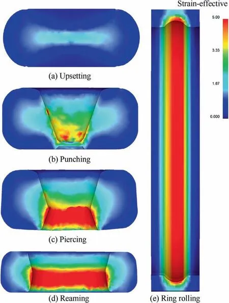
Fig.12 Effective strain distribution for different processes.
In the ring rolling stage,the deformation was also nonuniform(Fi.12(e)).The mandrel was in contact with the ring and underwent a feed motion toward the outer diameter of the ring blank,whereas the driver roll exerted a rolling force on the ring,gradually forming the raceway.Therefore,plastic deformation occurred first at the contact position between the inner diameter surface of the ring blank and the mandrel,followed by deformation at the contact position between the outer diameter surface of the ring blank and the driver roll,and then by deformation gradually extending toward the center of the ring wall from the two sides,all of which ultimately resulted in deformation non-uniformity.Meanwhile,the outer diameter surface of the ring blank was in contact with the driver roll,but the driver roll was not preheated and its size was relatively large,which resulted in fast heat dissipation and the lowest temperature.However,the inner diameter surface of the ring blank was in contact with a preheated mandrel,and the frictional resistance between the raceway and the mandrel was large,thereby resulting in a temperature higher than that of the outer diameter surface.The middle region inside the ring wall was not in contact with the rolls and had the highest temperature,thereby resulting in a temperature gradient along the RD.Due to the low temperature and large deformation resistance at the outer diameter surface,plastic deformation was less likely to occur in this region.Moreover,the plastic zone had a weak penetration ability,and thus,plastic penetration occurred within a limited range.However,the inner diameter surface was prone to plastic deformation.As the deformation continued at a fixed feed rate,the plastic zone near the inner diameter surface would ultimately penetrate into the ring wall along the RD.Therefore,raceway positions underwent the largest plastic deformation and the outer diameter surface exhibited the smallest strain,whereas the central part of the ring wall had moderate strain.This pattern was also reflected by the hardness gradient.Hardness was significantly higher at the raceway positions than at other positions,which indicated that the local deformation near the inner diameter surface was larger.The minimum hardness was on the outer diameter surface of the bearing ring,which was attributed to the fact that the metal workpiece did not undergo large plastic deformation at this surface in any stage of upsetting,punching,piercing,and ring rolling.In general,as the gap between the mandrel and the driver roll gradually decreased,plastic deformation gradually extended from the inner diameter surface to the outer diameter surface.That is,deformation continuously occurred with increasing diameter and decreasing thickness.Such a deformation pattern was consistent with the finding of Hua et al.,26who observed that deformation started near the inner diameter surface of a bearing ring and was least significant near the outer diameter surface.
As deformation was not uniformly generated and distributed during ring rolling,deformed microstructures manifested with different characteristics at different depths of the ring wall.During ring rolling,when the strain reached a critical value,DRX would occur;otherwise,SRX would occur.Raceway position 4 had greater strain than other positions and thereby would undergo DRX;however,due to excessive deformation at this position,recrystallized grains would continue to be elongated.Deformation at middle position 5 was moderate where the temperature was relatively high;hence,recrystallization would occur and recrystallized grains would be elongated.However,the deformation was still less significant compared to that at raceway position 4;hence,there were still some equiaxed recrystallized grains.At the outer surface position 6,deformation was the least significant and the temperature was relatively low,which failed to provide sufficient driving force for recrystallization;thus,DRX was less likely to occur.At this position,grains,in general,were large and elongated to a certain extent,but the grain aspect ratio was significantly smaller than that at position 4.
Fig.13 presents the evolution of microstructure at the raceway positions in different processing stages(e.g.,MSHF versus MSHFA),with analysis performed on the representative regions in the black rectangular frames.First,the M50 steel underwent complete austenitization when heated at 1120°C for a period of time,but primary carbides did not dissolve at the high temperature.Second,the workpiece was subjected to MSHF,in which grains were elongated and bulky primary carbides were uniformly distributed along the AD,forming flow lines of a regular pattern.Due to its high hardenability and a carbon content of 0.8%,the M50 steel formed a microstructural mixture of lath-shaped martensite and needle-shaped martensite after cooling.Finally,the bearing ring formed through the hot ring rolling stage was subjected to MSHFA,which allowed a relatively simple and fast spheroidization of high-carbon martensite:the two-phase region underwent partial austenitization whereas the residual carbide particles grew coarse and large.27After isothermal MSHFA,a granular pearlite structure with uniformly distributed carbides was obtained,and primary carbides remained,still in an orderly distribution along the AD.

Fig.13 Evolution of microstructure at raceway positions in different processing stages.
4.2.Effect of flow lines and aspect ratio of grains on mechanical anisotropy
Mechanical property anisotropy is mainly related to the fibrous second-phase structures,grain aspect ratios,28,29and textures30,31in steels.In this study,the bearing ring did not exhibit evident textures after MSHF and MSHFA,thereby ruling out the impact of textures on mechanical property anisotropy and narrowing the consideration to the effects of flow line and grain aspect ratio.A comparison of the mechanical properties after MSHF versus MSHFA revealed that EL along different directions decreased in the order of AD>CD>RD,with the EL along the AD being higher by 10.1% and 6.5% than that along the CD and RD,respectively.However,the tensile strength showed a different pattern.After MSHF,the tensile strength along the AD was higher by 8.3% than that along the CD and RD;after MSHFA,the tensile strength along the AD and CD was slightly greater than that along the RD,by only 1.6%.The significantly greater tensile strength along the AD compared to that along the other two directions after MSHF was attributed to the grains that were significantly elongated along the AD.In body-centered cubic(BCC)metals,brittle failure can be caused by dislocation glide within the grains.32The glide occurs at the yield stress σy,whose variation with the grain size can be expressed by the Hall–Petch relation,

where σ0is the lattice frictional stress required to move individual dislocations,andkis a constant.
Dislocations usually accumulate at the grain boundaries instead of propagating beyond them.When dislocations accumulate at the boundaries of deformed grains,they behave like cracks with a length proportional to the grain sized,strengthening the stress of the surrounding grains.In forging materials that contain elongated grains,drefers to the grain size perpendicular to the AD,namely the grain width.33As indicated by the above formula,the d of grains parallel to the tensile direction will be significantly smaller than that perpendicular to the tensile direction.That is,the crack length will be significantly smaller than the width of grains perpendicular to the tensile direction,making the corresponding σyincrease significantly.Therefore,the grain morphology parallel to the tensile direction will have higher tensile strength.In addition,the small crack length is favorable for hindering the movement of dislocations and the extension of cracks,which increases the EL of the alloy.
5.Conclusions
In this study,multi-stage forging and subsequent annealing processes were performed on M50 steel,the corresponding mechanical properties were measured,and the evolutions of flow lines and microstructures were analyzed,leading to the following main conclusions:
(1) By placing the punching slugs at the bottom of the blank and punching the blank with a V-shaped punch,a bearing ring with flow lines distributed along the outer contour could be obtained.
(2) The MSHF of the bearing ring was a process in which deformation gradually occurred from the inner diameter surface to the outer diameter surface of the bearing ring,with deformation showing cross-sectional nonuniformity.Deformation became less significant in the order of inner bearing ring raceway>middle of the ring wall>outer diameter surface,with evident grain EL at the inner bearing ring raceway.The bearing ring exhibited anisotropy in tensile mechanical properties,with its UTS and EL in the AD being superior to those in the RD and CD.
(3) After MSHFA,a granular pearlite structure with uniform carbide distribution was obtained,and evident recrystallization occurred at the inner bearing ring raceway,the middle of the ring wall,and the outer diameter surface,converting elongated grains into equiaxed grains.This made the microstructure more uniform,with the average grain size at the above-mentioned three regions dropping to 6.38,6.41 μm,and 6.89 μm,respectively.However,the anisotropy of mechanical properties still existed,that is,the mechanical properties were better in the AD and CD along the flow lines than those in the RD perpendicular to the flow lines.The UTS in the three directions was 915 MPa,930 MPa,and 930 MPa,respectively,and the EL was 27.3%,28%,and 29.1%,respectively.
(4) Grain shape had a significant effect on the UTS and EL of the bearing ring.After MSHF,the axial UTS was higher by up to 8.3% than the UTS in the other directions,and the axial EL was higher by 10.1% than the EL in the other directions.Flow lines did not have a significant impact on UTS,with the axial and circumferential UTS being higher by only 1.6% than the radial UTS.However,flow lines had a significant impact on EL,with the axial EL being higher by 6.5% than the radial EL.
(5) Primary carbides could not be eliminated by MSHF and MSHFA but only their distribution could be changed through the forging process.
Declaration of Competing Interest
The authors declare that they have no known competing financial interests or personal relationships that could have appeared to influence the work reported in this paper.
Acknowledgement
The authors gratefully acknowledge the financial support from the National Natural Science Foundation of China (No.51974099).
杂志排行

CHINESE JOURNAL OF AERONAUTICS的其它文章
- Parameter effects on high-speed UAV ground directional stability using bifurcation analysis
- Supersonic flutter control and optimization of metamaterial plate
- Review of in-space assembly technologies
- Utilisation of turboelectric distribution propulsion in commercial aviation:A review on NASA’s TeDP concept
- The influence of inlet swirl intensity and hot-streak on aerodynamics and thermal characteristics of a high pressure turbine vane
- Full blended blade and endwall design of a compressor cascade