The influence of inlet swirl intensity and hot-streak on aerodynamics and thermal characteristics of a high pressure turbine vane
2021-10-25ZakariaMANSOURIRiyadhBELAMADI
Zakaria MANSOURI ,Riyadh BELAMADI
a ABYLSEN Science &Technology Rhoˆne Alpes,Grenoble 38000,France
b E´cole Supe´rieure de Technologies Industrielles (ESTI),Annaba 23000,Algeria
KEYWORDS Aerodynamics;Heat transfer;Hot-Streak;HP turbine;NGV;Swirl intensity
Abstract In modern gas turbines,the High Pressure Turbine(HPT)is exposed to an extreme thermal environment due to the burned gases leaving the combustor.The burned gases are characterized by flow and temperature distortions that effect the aerodynamics and heat transfer of the turbine.The purpose of this paper is to investigate numerically the effect of the intensity of the swirling flow combined with the temperature non-uniformity ‘‘Hot-Streak”(H-S) on the aerothermal performances of a HPT Nozzle Guide Vane (NGV).The investigations are conducted on the solid untwisted NGV annular cascade developed in NASA Lewis Research Center.Four swirl intensities(|Sn|=0,0.1,0.25 and 0.5),two swirl orientations (positive and negative) and two hot-streaks(rounded and radial)at the NGV inlet are considered.The simulations are done by solving the Reynolds Averaged Navier-Stokes (RANS) equations using ANSYS-CFX software.The results show that the H-S with swirl undergoes twisting following the orientation of the swirl.The H-S twist is aggressive under positive swirl compared to the negative swirl case.The inlet swirl generates a new secondary flow structure,so called Swirl Vortex(SV),which induces more aerodynamic losses.The aerodynamic efficiency under negative swirl found to be higher than that under positive swirl.The maximum temperature on the vane surface is controlled by the radial transport of the SV towards the endwalls.
1.Introduction
The temperature of the hot burned gases leaving the combustion chambers of the modern gas turbines is well above the melting point of the blades alloy.Continuous exposure to such extreme thermal environment would result in blades thermal fatigue and turbine failure.Due to the combined effects of the swirling flame from fuel injectors,dilution and film cooling from the combustor liners,the combustion chamber outlet generally experiences velocity and temperature distortions,which present both strong gradients in circumferential and radial directions.The turbine Nozzle Guide Vanes (NGV)are severely influenced by these strong gradients since they are in front of the combustor exit.The velocity distortion caused by the swirling flow would affect the NGV secondary flow structures,the pressure distribution and the stage efficiency.The temperature distortion caused by the flame heat release and coolant flow is well known as Hot-Streak (H-S)and it would affect particularly the thermal load of the NGV.The turbine aerothermal behavior under such nonuniform inlet conditions are of very important interest during the design phase of the high pressure stage components(NGV,rotor blades,shrouds,tips,etc.) to enhance blades cooling schemes and stage efficiency.For example,Fig.1 shows a HPT segment of a turbofan engine,which constitutes of two similar NGV.The segment is internally cooled and film cooled also.It is clearly seen that the right-hand NGV is in good condition,however,the left-hand NGV is in poor condition.This later is damaged on the Leading Edge (LE) with several small cracks and even partially crumbled,after few years of service.It can be easily guessed that the left-hand NGV is the one in front of the flame nozzle (fuel injectors) of the combustor.Thus and without doubt,the blade failure on the LE owing to thermal stress fatigue caused by the H-S.Furthermore,the damaged NGV should have a different arrangements of cooling holes than the intact NGV,since they don’t experience the same thermal load.Or,the non-uniform inlet conditions(H-S and swirl) should be attenuated to increase the lifetime of the HPT segment.
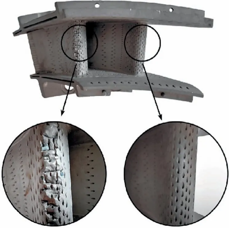
Fig.1 Segment with two NGV from a high pressure turbine of a turbofan engine.
H-S is investigated individually (without swirl) during several years in the literature to reveal its effect on the blades(NGV and rotor) heat transfer and its migration mechanisms through the turbine annular passage.1–8For instance,Salvadori et al.4studied numerically a High Pressure Turbine(HPT) stage and they showed that the presence of a H-S increases the heat transfer rate by 20% on the NGV Pressure Side (PS) and 50% on its Suction Side (SS).This compared with a uniform inlet temperature distribution.He et al.5investigated computationally the effect of the H-S counts,corresponding to different numbers of burners,on the heat transfer of a turbine stage.Their analysis showed that the variation of the circumferential H-S numbers alters considerably the migration of temperature distortion and the heat load on the blades.Povey et al.6performed a joined experimental and numerical study on a HPT with the presence of two clocking positions of the H-S with respect to the NGV.They reported that the heat transfer rate on the NGV SS at the midspan was increased,compared to uniform inlet temperature condition,when the H-S is aligned with the NGV leading edge.The heat transfer rate was slightly decreased when the H-S is aligned with the NGV passage.Feng et al.7simulated the first 1.5 stage turbine of GE-E3 engine.They found that the influence of the H-S on the thermal load of the second stage NGV could be attenuated by matching the clocking positions of the second stage NGV and H-S.Consequently,the turbine efficiency could be also enhanced.Wang et al.8carried out an unsteady computational study on a HPT stage under the effect of H-S and various inlet turbulence intensity.Their results indicated that the elevated turbulence intensity led to favorable turbine rotor temperature gradients and turbulence induced HS reduction mainly occurred in the NGV passage.In addition,the H-S dispersion was directly related to the temperature distributions.
In the above studies,the residual swirling flow at the HPT inlet generated by the combustor swirlers was neglected.So,the findings may not correspond to real engines conditions.Few studies have been done to explore the effect of individual inlet swirl without H-S.Shih and Lin9investigated numerically a NGV features a modified LE fillet with and without swirl.Their obtained results show that both LE fillet and inlet swirl can reduce the aerodynamic losses and surface heat transfer.The difference in total pressure from the NGV inlet to its exit was reduced by more than 40% under swirl condition.Heat transfer rate was also reduced by more than 10% on the NGV and by more than 30%on the endwalls.Qureshi et al.10conducted a detailed experimental and computational investigations of the effect of aggressive inlet swirl on the aerodynamic and heat transfer characteristics of a HP NGV.A combustor swirl simulator has been designed and coupled with the MT1 research turbine,to this purpose,in the Oxford Turbine Research Facility.It was reported that the swirl significantly altered the secondary flow structures and NGV loading distributions near the endwalls.The boundary layer at the NGV was redistributed,causing it to collect in certain regions and dissipate in others.This conducted to significant changes in Nusselt number explained by streamline divergence and convergence on the blade surface.Schmid and Schiffer11simulated the effect of inlet swirl on aerodynamic losses,secondary flow pattern and heat transfer in a combustion chamber with a downstream turbine NGV cascade.The combustor was not equipped with swirlers but the effect of swirling motion was modeled by inlet boundary conditions.They analyzed three different aspects,which are:the swirl intensity,the alignment of the swirl core and the swirl orientation (positive or negative).They noted the following:increasing the swirl intensity results in reduced heat transfer rate within the NGV passage and higher pressure loss.Heat transfer through vanes and endwalls is maximal if the swirl core is aligned with the NGV LE and counter rotating (negative) swirl.
Some recent researches tend to consider both the influence of H-S and swirling flow simultaneously.Studying them at the same time is expected to yield more detailed understanding about the interaction between the combustion chamber and HPT.Khanal et al.12presented a numerical investigation of the MT1 HPT behavior under the combined influence of the swirl and H-S.They revealed distinctive radial migrations of the H-S in the NGV and rotor passages with considerable impact on the aerothermal performance.They illustrated that the blade heat transfer characteristics and their dependence on the clocking position can be strongly affected by the swirl direction.Liu et al.13investigated the H-S migration across tip clearance and heat transfer on rotor tip in a HPT with different inlet swirl orientations and clocking positions.Their results indicated that the influence of swirl on pressure distribution focuses on the SS.Positive swirl blew hotter fluid to the shroud when it is aligned with the LE.In all cases with swirl,the thermal load on the second half of the blade tip is effectively reduced,which is good for cooling rotor blade tip,according to the authors.They reported also that the positive swirl aligning with the NGV LE will be the best choice for protecting rotor blade tip.Wang et al.14conducted conjugate heat transfer analyses on the first stage NGV of the GE-E3 engine to reveal the effects of inlet H-S and swirl on vane Film Cooling (FC).They considered different cases with H-S only and with combined H-S and positive/negative swirls.They indicated that the variations of incidence angle combined with influences of radial transportation of the swirl vortex worsen the FC attachment,decrease the FC efficiency and increase the thermal load on the NGV.A negative swirl aligned to the NGV leads to decreasing the temperature at the LE and the PS.Li et al.15investigated the effects of inlet nonuniformity (swirl with H-S) alignments and orientations on the 1.5 stage HPT of LISA facility at ETH Zurich using unsteady simulations.They found that the H-S clocking position dominates the averaged temperature,while the swirl orientation dominates the radial distribution.The clocking effect strongly impacts both time-averaged and instantaneous turbine performances.They concluded that the aligned LE positive swirl configuration has the best performance,where the swirl carries the H-S radially in the rotor passages and redistributes the temperature on the rotor surface.
To be more consistent with the real engines conditions,the residual swirl at the combustion chamber outlet should be represented and evaluated properly.Usually,the swirl intensity is not aggressive at the HPT inlet and it is attenuated under the effects of several parameters (initial swirl of the injector,16,17combustor geometry,18-20coolants leaving the liner holes...etc.).For example,short combustors of aero-engines feature relatively high residual swirl at their exit compared to land gas turbines with long combustors that feature weak residual swirl at HPT inlet.In addition,combustor injectors are generally equipped with two to three swirlers and they are fully or partially turned-on according to the engine operating regime.Thus,the HPT inlet swirl intensity could be variable depending on the combustor operating conditions.Investigating the influence of the swirl intensity is expected to yield more comprehensive understanding about the interaction between the swirling flow and aerothermal characteristics of the HPT.There appear to be hardly any published works on the effects of swirl intensity combined with the H-S.The study by Schmid and Schiffer11appears to be the only known in open literature that investigates the effect of swirl intensity on turbine NGV aerothermal behavior,but without H-S.
The present work focuses on filling this knowledge gap and studying the effects of both the H-S and swirl intensity to be more consistent with real engine condition.By varying the swirl intensity,this indicates that swirlers of combustor injector are in partial or full running mode according to the need of the engine regime.Moreover,the following aspects are analyzed:(A) the H-S migration,(B) the thermal and force loads on the vane,(C)the secondary flow structures and(D)the row aerodynamic efficiency.The solid NGV annular cascade21,22developed in NASA Lewis Research Center is adopted to reach the purpose of the present numerical study.This cascade operates under an inlet to outlet pressure ratio,which is representative to real aero-engine.Two types of H-S are investigated,radial and rounded.The radial H-S is similar to those investigated in early academic studies,whereas the rounded H-S is similar to the temperature distribution at the outlet of a real engine combustion chamber.Four swirl intensities(|Sn|=0,0.1,0.25 and 0.5)at each positive or negative orientations are evaluated.One clocking position is chosen with respect to the NGV LE,where the H-S and swirl are fitted together.
The rest of the paper is organized as the following:Section 2 contains the geometrical details of the used NGV annular cascade with its mesh,the numerical method used and the CFD code validation.Section 3 shows the adopted H-S distributions with the inlet swirl intensities and orientations.Then,Section 4 treats and discusses the results of H-S migration through the NGV.Next,Section 5 reveals the aerodynamic performances of the NGV under the various swirl intensities,while Section 6 discusses the thermal characteristics of the NGV including surface temperature and heat transfer coefficient.Finally,Section 7 concludes the discussed results and suggests guidance for cooling schemes designs.
2.Cascade geometry and simulation validation
2.1.Cascade geometry
The present investigation is performed on the solid untwisted NGV annular cascade developed in NASA Lewis Research Center.21,22Fig.2 depicts the investigated stator annular cascade geometry with the numerical domain.The cascade annulus features 36 NGV with a hub to tip ratio of 0.85 and a tip radius of 0.254 m.It is designed for a fully axial inflow conditions and an exit hub-static to inlet-total pressure ratio of 0.6705.The rest of the geometric parameters and flow conditions are given in Table 1.

Fig.2 3D view of NGV geometry with mesh and numerical domain.
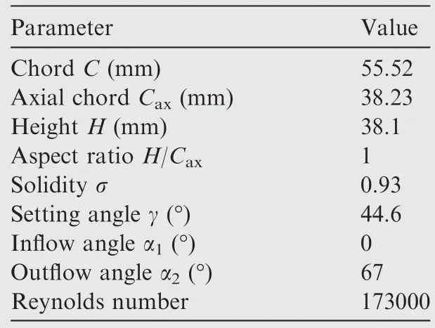
Table 1 NGV annular cascade details.
2.2.Grid and boundary conditions
An example of the grid used is shown at the upper endwall in Fig.2.It is created with ANSYS-TurboGrid,using multiblock topology.Each block supports a structured mesh,which leads to an H-O–H type grid for the NGV.The thickness of the cell adjacent to the cascade walls (upper and lower endwalls and the NGV) is fixed at values that guaranteesy+values around 1.
The numerical domain and boundary conditions are also shown in Fig.2.The mainstream inlet is located at one axial chord from the vane LE and the outlet is located at one axial chord from the vane Trailing Edge (TE).A pair of periodic boundaries is imposed at the pitchwise direction so that the numerical domain covers only one vane passage.The boundary conditions are imposed as following:at the mainstream inlet,a total pressure is imposed with medium turbulence intensity of 4% and a temperature of 288 K.At the outlet,a static pressure is used with an averaging over the whole surface option.For all the walls,a non-slip and adiabatic conditions are applied.
2.3.Numerical parameters
The simulations are performed using ANSYS-CFX CFD software,23which is a general purpose CFD code with a focus on turbomachinery.24-28The solutions are obtained by solving the 3D steady compressible RANS equations using the finite volume method.The high resolution method is adopted for both the advection scheme and turbulence numerics.The equation of the heat transfer is solved using the total energy option.For the fluid time scale control,a conservative option is selected with time scale factor of 1.The turbulence model adopted is the two equationk-ω SST(Shear Stress Transport)similar to Refs.8,9,29Various convergence criteria are used,so that the numerical results will be effectively accurate.This is done by checking the static pressure at the NGV surface,the static pressure and the mass flow rate at the outlet of the domain.In addition,the Root Mean Square (RMS) residuals of the mass conservation,the momentum,the energy,the tur-bulent kinetic energy and the specific rate of dissipation equations are less than 10-6.
2.4.Grid sensitivity and numerical validation
To ensure a sufficient modeling of the compressible flow around the NGV annular cascade,a grid sensitivity analysis is conducted.Three different grids are used in this study:coarse with 0.59 million nodes,medium with 1.234 million nodes and fine with 2.7 million nodes.The influence of the grid refinement on the numerical solution is shown in Figs.3 and 4.Figs.3(a)–(c) present comparisons of the measured and computed surface-static to total-inlet pressure ratio distributions at different spans of the vane.It can be seen that there are no substantial differences between the medium and the fine grids at all spans.The coarse grid shows a very slight shift,which can be neglected,over the vane SS near the 50% of the chord region.At 50% of span,the computed solutions have a good agreement with the experimental data at each point.At 13.3% of span,the predictions are very well except near the 45%of the chord region,where the SS Pressure Ratio(PR) is slightly underestimated.At 86.6% of span,the predictions are good at the vane SS and they are above the experimental data at the NGV SS.It is believed that the slight discrepancies close to the endwalls near the SS is due to the presence of the corner vortex(secondary flow).The flow in this region is complex due to the interaction of the endwall and NGV boundary layers,which affects slightly the numerical predictions.Fig.3(d)shows the predicted mixed-out total pressure loss coefficient downstream the NGV compared with the experimental results from Ref.22The computed loss coefficient agrees very well with the experimental one across the whole span except near the hub region,which overestimates slightly the values.However,the coarse grid show loss values slightly above the values of the other grids.

Fig.3 Computed and measured surface pressure ratio at different spans and mixed-out total pressure loss coefficient profiles.
Figs.4(a)–(c)present comparisons of the three grids results of the Heat Transfer Coefficient (HTC) at different spans of the vane.Note that there are no experimental data available for the HTC to perform the validation.However,the HTC should also be selected for grid sensitivity analysis.It can be seen that there are no substantial differences between the medium and the fine grids at all spans.The coarse grid shows a small difference,which is very remarkable over the vane SS at 13.3%of span.Moreover,the overall validation of the present numerical results is very well and consequently the medium grid is used for the rest of this study to save the computational time.
3.Inlet hot-streak and swirl
In the present paper,the two H-S shown in Fig.5 with a temperature ratio of 1.28 are evaluated.The first H-S (Fig.5(a))has a radial distribution with quasi-uniform maximum temperature from 15% to 85% span and a low temperature gradient from 0% to 15% span and from 85% to 100% span.The low temperature gradient is used to present the effect of dilution and film cooling from the combustor liners.The second H-S(Fig.5(b))is rounded and has circumferential and radial distributions similar to Refs.3,5,8,13–15The H-S center is located at the mid span and aligned with the vane LE.

Fig.5 Inlet hot-streak.
Two swirl orientations defined in Fig.6 are introduced in the inlet boundary conditions along with the H-S to study the influence of inlet swirl.The positive swirl(Fig.6(a))rotates in the clockwise direction,whereas the negative swirl (Fig.6(b)) rotates in the anti-clockwise direction.Four swirl intensities,are evaluated at each swirl orientation and they are equal to 0,0.1,0.25 and 0.5.The expression of swirl number depends on the injector geometry and flow profiles:16,17
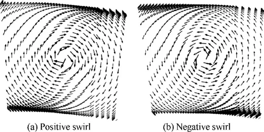
Fig.6 Inlet swirl vectors.
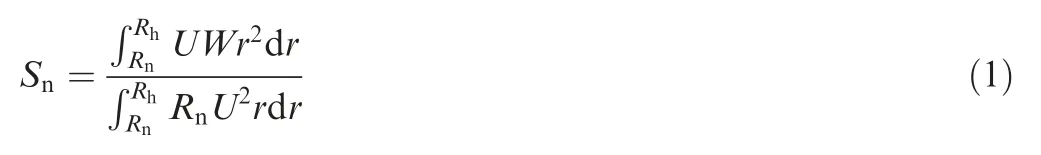
whereris the swirler radius,RnandRhare the internal and external radii of the swirling injector,respectively.Uis the averaged axial velocity andWis the averaged tangential velocity.Note that the swirl expression could be simplified to represent only the ratio between the velocities (Sn≈W/U),as found in Refs.19,20.
The investigated combinations of H-S,swirl orientation and intensity are summarized in Table 2.In order to highlight the effects of the swirl intensity on the H-S migration,the cases with only H-S and without swirl(Cases 1 and 8)have been set as the baseline.

Table 2 Summary of investigated cases.
4.Hot-streak migration across NGV
4.1.Effect of swirl intensity on H-S migration
The rounded H-S migrations under various negative swirl intensities in the NGV passage at four chordwise planes are shown in Fig.7 using temperature contours.Two planes upstream and downstream the vane are designated as‘‘Front-plane”and‘‘Aft-plane”and two other planes intersect the NGV near the LE and TE regions are designated as ‘‘LEplane”and‘‘TE-plane”.At each swirl numberSn(swirl intensity),after impinging the LE,the H-S divides into two parts which travel across the chordwise and join together downstream the TE.The PS part contains the largest portion of H-S compared to the SS part.The H-S exhibits distortion across the passage,due to the interaction with the vane profile and boundary layers,and downstream the TE owing the wake.As the H-S wraps around the NGV,it remains in contact with it surface.Regarding the swirl effect,it is clear that the H-S with swirl (Sn≠0) undergoes twisting following the orientation of the swirl,anti-clockwise for this case.The twisting strength increases as the swirl number increases.At low swirl number (Sn=-0.1),the H-S has a quite similar migration as the baseline case(Sn=0).This is due to the very weak tangential momentum brought by the inflow.At medium swirl number (Sn=-0.25),the rotational momentum of the flow become remarkable and contributes to the deformation of the H-S at each cross plane.For high swirl number(Sn=-0.5),the H-S becomes highly distorted with stronger gradients in both the radial and circumferential directions compared with those of the inlet.The strong temperature gradients are caused by the high flow mixing under such high swirl.For more detailed analysis,it can be suggested to compare the H-S shape for each swirl intensity at the Aft-plane downstream the NGV TE.Without swirl,the H-S is twisted following the clockwise direction under the effect of the NGV profile.As the swirl intensity increases,the swirling flow straightens the positive twisted H-S to turn it to the negative direction.For example,the H-S ofSn=-0.25 becomes straight and forSn=-0.5,it becomes twisted in the negative direction and more spread out.
4.2.Effect of swirl direction on H-S migration
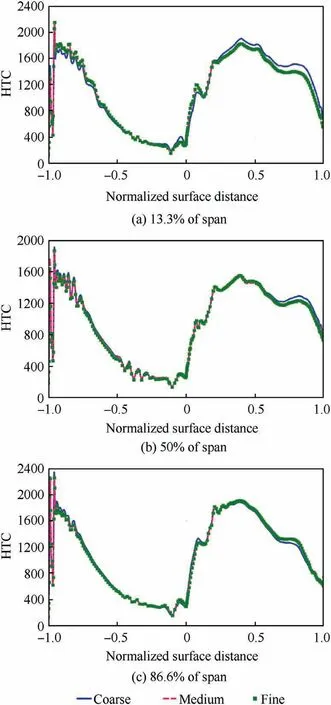
Fig.4 Profiles of heat transfer coefficient at different spans for three grids.
The rounded H-S migrations under two swirl orientations at the same absolute intensity of |Sn|=0.25 are shown in Fig.8 using temperature contours.The same previous four chordwise planes are kept.A positive swirl is seen to twist the H-S clockwise as expected.The H-S is twisted aggressively under positive swirl compared to the negative swirl case.It was found that the baseline case (Sn=0 at Aft-plane in Fig.7)promotes the H-S turning in the positive direction due to the blade profile.Thus,the introduction of positive swirl provides additional twist to the H-S and it results higher twist than the negative swirl case.This is clearly shown at the Aft-plane.In addition,the positive swirl is found to transport the hot fluid core to the lower endwall (hub) region on the vane PS and towards the upper endwall (shroud) on the blade SS.The opposite is evident in the negative swirl case.The mechanism of hub/shroud hot fluid transport on the NGV surfaces is managed by a new formed secondary flow structure as it will be revealed in Section 5.2.Thus,the swirl loads up the NGV surfaces with hot fluid in a different distribution than it was in the baseline H-S case.This will alter directly the cooling schemes requirements of both surfaces of the NGV under swirl conditions.

Fig.7 Migration of rounded H-S across NGV passage at different negative swirl intensities.
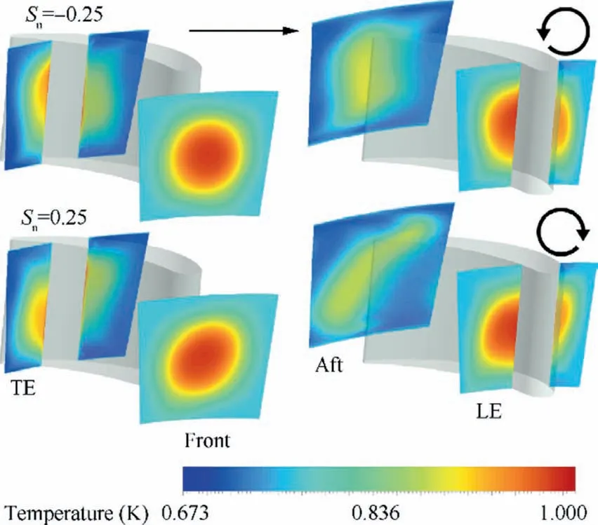
Fig.8 Migration of rounded H-S through NGV passage at two swirl directions.
4.3.Effect hot-streak type
The migrations of the radial H-S under no swirl (Sn=0) and high positive swirl ofSn=0.5 are presented in Fig.9 using temperature contours.The migration of the rounded H-S atSn=0.5 is also shown in Fig.9 for comparisons.The same previous four chordwise planes are kept.At each of the three shown cases,it can be seen that the H-S undergoes decreasing of temperature as it travels across the cascade,as expected.This is due to the compressibility effects which promotes velocity increasing that reduces the fluid temperature under constant total temperature through the cascade.This can be simply verified using the famous equation of isentropic Mach number as a function of temperatures.Note that this decrease of temperature is also valid for the previous shown cases in Figs.7 and 8.For the radial H-S without swirl,the temperature gradient is not highly affected through the passage and the coolant film (low temperature) is kept near the endwalls except near the vane PS.At the junction between the PS and endwalls,the coolant film is replaced by hot fluid from the passage due to the interaction of the boundary layers under high pressure effect.For the radial H-S with swirl,the temperature distribution is aggressively distorted at each cross-section of the cascade.For example,at the Front-plane,the H-S is twisted in the positive direction and the coolant film exhibits variable thickness through the pitchwise direction.At the LE-plane,the film is replaced by hot fluid near the blade surfaces (PS and SS) and it is driven radially from the endwall towards the passage in the mid passage region.Downstream at the Aft-plane,the radial H-S is dissipated and mixed with the coolant film under both effects of swirl and wake.Note that the near endwalls regions contain the highest temperatures(opposite to the inlet gradient) and the passage is filled with both high and low temperatures.This will affect the film cooling requirements at the NGV endwalls at this combined radial H-S and swirl condition.For the rounded H-S with swirl,it exhibits also an aggressive twist at each cross-section.The temperature distributions at each plane is not similar to that of the radial H-S due to the difference of the initial inlet distribution.Downstream the NGV TE,the rounded H-S is no longer centered at the Aft-plane as it was the case for all the other swirl numbers.The H-S is divided in two hot zones,which are close to the hub and shroud.As a conclusion,the distortion of the H-S at this high positive swirl (Sn=0.5) seems to be higher than the distortion caused by the high negative swirl(Sn=-0.5).This indicates that the secondary flows of the positive swirl are stronger that those of the negative swirl,as it will be shown in Section 5.2.

Fig.9 Migration of rounded and radial H-S through NGV passage at high positive swirl.
5.Aerodynamic parameters across NGV
5.1.Effect of swirl intensity on vane loading
The vane surface pressure ratio of all swirled cases agree with that of the baseline case at the midspan 50%,as shown in Fig.10.There is only a little difference at the forward region of the NGV PS at the highest swirl numbers.However,compared with the baseline case without swirl (Sn=0),the inlet swirling flow has considerable effect on NGV surface pressure distributions near the hub (H=13.3%) and shroud(H=86.6%).The major differences locate at the the first half of the vane following the chordwise distance.For negative swirl,as the intensity increases,the pressure distribution at the LE changes from the midspan towards both upper and lower endwalls,as follows.Near the hub (H=13.3%),the PR increases at the PS and decreases at the SS,since the high pressure location is shifted to the vane PS.Near the shroud(H=86.6%),there is a reverse effect of the PR,where the the high pressure location is shifted to the vane SS.This leads to a decraease of the PR at the vane PS.These reversed pressure distributions are due to the change in the inflow angle brought by the swirl effect.Thus,the near hub ragion faces negative inflow angles,whereas the near shroud ragion faces positive inflow angles.Negative angle leads the inflow to impact the PS,while positive angle leads the inflow to impact the SS.The opposite of these distributions is evident in the positive swirl intensities.So,the positive swirl brings fluid with positive incidence angle onto the PS and with negative incidence angle onto the SS.

Fig.10 Effect of swirl intensity on surface pressure ratio at different spans.
The variations of the vane loading under different swirl intensities at the same previous spans are plotted in Fig.11.The NGV loading is calculated using the length integral of the pressure force at each of the three spans (13.3%,50%and 86.6%).At a constant swirl intensity,the blade loading exhibits a variation from the hub to the shroud,as expected.This is due to the difference of the exerted pressure on the vane surface from the hub to the shroud.At a fixed span,the swirl flow variation has a considerable effect on the vane loading.The vane loading values for the negative swirl differs from the values of the positive swirl at each span.Because the three spans feature the presence of secondary flows structures (as it will be shown in the next section),these structures alter the exerted force on the vane.For example,the near hub secondary flow does not behave in the same way under the effect positive or negative swirl,which leads to a change in the vane loading.

Fig.11 Effect of swirl intensity on blade loading at different spans.
5.2.Effect of swirl intensity on secondary structures
The basic secondary flow structures in the turbine NGV without swirl are shown in Fig.12 using iso-surface ofQ-criterion.Two main structures can be distinguished near the endwalls,which are the Horse-Shoe Vortex (HSV) and the Corner Vortex(CV).The details of the formation of these secondary structures could be found in Ref.30It is clear that both the CV and HCV structures at the shroud are larger than those at the hub and this is due to the annular form of the cascade.

Fig.12 3D secondary flow structures of baseline case.
The secondary flow structures under the effect of swirl are given in Fig.13.It is important to note that the cases with low swirl(Sn=-0.1 and 0.1)are similar to the baseline case regarding the flow structures.This is why they are not shown along with the other swirl cases in Fig.13.As the swirl intensity become important,a new secondary structure appears around the midspan of the vane.The structure is so called Swirl Vortex (SV).At |Sn|=0.25,the SV is formed only at the SS near the midchord and midspan.The mechanism of SV formation can be decrypted as follows.The swirl impinges on the vane LE and divides into two parts transported through the chordwise.At the vane SS,the flow accelerates under the compressibility effect and NGV shape,which provides the SS swirl part with additional momentum.Meanwhile,the SS boundary layer exhibits an increasing thickness due to the transition.Then it interacts with the swirl and twists to form the SV.This later migrates radially towards the hub if the swirl is negative or radially towards the shroud if the swirl is positive.At high intensity (|Sn|=0.5),the inlet swirl comes with high momentum and a pair of rotating vortices(two SV structure legs) is generated immediately at the midspan of the LE.Similar vortices are also found by Li et al.15The SV structures rotate in the same direction as the inlet swirl and they both migrate in opposite radial direction through the passage.The swirling strength of the SS leg is higher than that of the PS leg due to the acceleration of the flow at the SS.At negative swirl,the SS leg moves downward and intensifies the hub CV to be formed earlier on the LE/hub junction with taller structure compared to the case ofSn=-0.25.At positive swirl,the SS leg travels upward and intensifies the shroud CV to be larger compared to the case ofSn=0.25.Furthermore,the appearance of this new SV and the intensification of the corner vortices must have an effect on the aerodynamic losses of the NGV cascade,which will be evaluated later.

Fig.13 3D secondary flow structures under different swirl intensities.
5.3.Effect of swirl intensity on vane surface streamlines
The basic flow topology on the NGV surface without swirl is illustrated in Fig.14 using two-dimensional streamlines.Since the inlet flow angle is zero,the flow/NGV interaction generates a straight Stagnation Line (SL) indicated by blue dashed line on the LE,as expected for untwisted blades.The surface flow leaves the LE to form almost parallel lines through the vane surfaces.At the SS,the streamlines are not parallel near the endwalls and they converge to one single line,the so called Reattachment Line(RL)indicated by red dashed line.This line is generated under the effect of the corner vortex,where the boundary layer of the endwall near the SS is sucked by the CV and joins the vane boundary layer.Note that the RL near the shroud extends more through the NGV span compared to the RL near the hub.This confirms that the CV at the shroud is larger than the one at the hub.

Fig.14 Surface streamlines at NGV for baseline case.
The surface streamlines on the NGV under different swirl intensities are given in Figs.15 and 16.The same colors of the topology lines are kept,which are blue and red for the SL and RL,respectively.A new purple dashed line is used and designated as the Median Line(ML).It shows an arbitrary median streamline to follow its trajectory under swirl through the chordwise direction.The introduced swirl motion alters considerably the flow topology on the vane surface and reveals the impact of the secondary flows on the NGV boundary layer.For negative swirl numbers (Fig.15),as the swirl intensity increases,the SL becomes inclined and twisted,its lower side shifts towards the PS and its upper side shifts towards the SS.This indicates that the swirl affects the inflow angle by negative incidence on the PS and positive incidence on the SS.This explains the pressure distribution on the NGV reported in Section 5.1,where a pressure increase is found at the PS near the hub and SS near the shroud.At the vane PS,the high swirl causes the boundary layer to accumulate close to the shroud(i.e.see ML atSn=-0.5).This is due to the presence of the SV,which drags the boundary layer fluid from the midspan region towards the shroud.At the vane SS,the SV leg has a reverse effect on streamline pattern redistribution,where the ML approaches more and more to the hub region,as the swirl intensity increases.It seems that the negative swirl has not an influence of the shroud CV,as the shroud RL remains consistent at each intensity.However,the hub RL is affected and especially at high intensity to be larger.This indicates that the hub CV becomes stronger under the intensification of the SV.
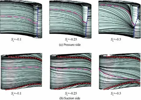
Fig.15 Flow topology on NGV surface under negative swirl intensities.
For positive swirl (Fig.16),the increase in intensity affects the SL in similar manner as the negative swirl (inclination,twist...etc.),but with a reversed orientation.The SL lower side is pushed towards the SS and the upper side is dragged towards the PS.Thus,the SS features positive inflow angles and the PS features negative inflow angles.On the PS,the high swirl causes the boundary layer to collect near the hub and dissipate near the midspan.On the SS,a reverse observation is true.This causes the SV to interact with the shroud CV (i.e.the ML is versy close to the shroud RL atSn=0.5).As conclusion,the inlet swirl results in vane surface fluid redistribution to be accumulate in the endwall regions and dissipated in midspan region.
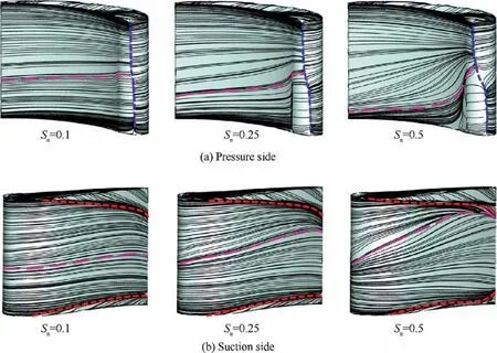
Fig.16 Flow topology on NGV surface under positive swirl intensities.
5.4.Effect of swirl intensity on losses
It is well known that the secondary flows induce aerodynamic losses downstream the blade passages.The losses are evaluated using aerodynamic row efficiency31at each studied case and shown in Fig.17.The definition of row efficiency is given by:

Fig.17 NGV efficiency under effect of swirl intensity.

whereP0,exitandPexitare the total and static pressures at the cascade exit,P0,inletis the total pressure at the inlet and γ is the specific ratio and equals to 1.4.
It can be seen that the baseline case without swirl presents the highest efficiency of 93.86%.Indeed,the NGV is designed for a fully axial inflow condition,which generates the weakest secondary flows among other flow incidence angles.Consequently,the losses are minimum and the aerodynamic efficiency is maximum.At inlet swirl conditions,it can be notices that the negative swirl cases have higher row efficiency than the positive swirl cases.For example,the efficiencies are 93.07%and 92.92%forSn=-0.5 and 0.5,respectively.This is explained by the fact that the positive swirl induces strong swirl vortices compared with negative swirl(i.e.relatively large size of SV atSn=0.25 compared to that ofSn=-0.25).Also,the positive SV intensifies the CV considerably compared the negative SV (i.e.the large shroud CV atSn=0.5 compared to the hub CV atSn=-0.5).Thus,the best design of HPT NGV should take into account fuel nozzles with negative swirl orientation and other geometric parameters providing the lowest possible swirl intensity at combustor outlet.
6.Thermal characteristics on NGV surface
6.1.Effect of swirl on surface temperature
Fig.18 shows the temperature distribution of the rounded H-S case on the vane surface for the baseline (Sn=0) and high swirl positive (Sn=0.5) and negative (Sn=-0.5) cases.For the baseline case,the H-S is printed on the NGV surface without remarkable change in its distribution.In other words,the maximum temperature is centered on the vane midspan from the LE to the TE (i.e.see the black dashed arrow atSn=0) and the minimum temperatures are located near the endwalls.Note that the near endwalls temperature at the SS is lower than the temperature at the same regions on the vane PS.This is due to the corner vortices which bring cold fluid from the endwalls boundary layer and put them in contact with the neighboring SS junction.For positive inlet swirl,the maximum temperature is dragged to the hub region on the vane PS and towards the shroud on the blade SS,as indicated by the curved dashed arrows.This confirms what was reported in Section 4.2 about the radial transport the hot fluid core under positive swirl.It is evident that the redistribution of the temperature contours (compared with the baseline case)is managed by the new formed swirl vortex.Thus,the maximum temperature follows the radial displacement of the hot SV core through the NGV surfaces.For negative inlet swirl,an opposite radial displacements of the maximum temperature are shown.Moreover,the near endwalls temperature at the SS is strongly affected by the swirl orientation.The intensified upper or the lower CV,depending on the swirl direction,promotes always the lowest temperature at these regions.Finally,and regarding the cooling design aspect,the grid of cooling holes should be adapted under swirl conditions to optimize the NGV surface cooling near the endwalls.
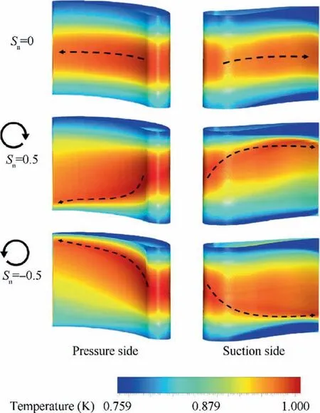
Fig.18 Surface temperature distribution under various swirl conditions.
6.2.Effect of swirl on surface heat transfer
Fig.19 depicts the heat transfer coefficient contours of the rounded H-S case on the NGV surfaces,for the baseline(Sn=0) and high swirl positive (Sn=0.5) and negative(Sn=-0.5) cases.Generally,the HTC (h) is derived from the near wall heat fluxqwformulation:
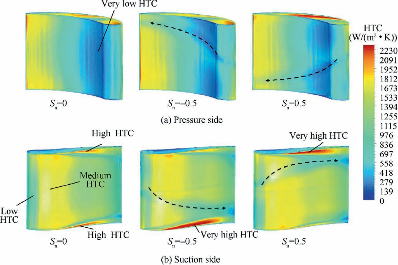
Fig.19 Contours of surface heat transfer coefficient under various swirl conditions.

where ρ andcpare the fluid density and heat capacity respectively,u*is the velocity scale in the logarithmic region of the boundary layer andT+is the non-dimensional near-wall temperature.u*andT+represents the viscous term and the thermal term,respectively.ΔTis the temperature difference between the fluid and the NGV wall.The velocity scaleu*is a function of the model constantCμ=0.09 and the Turbulence Kinetic Energy (TKE)k.The TKE is a function of the turbulent viscosity μtand the shear stress τ.The nondimensional temperatureT+is proportional to a nondimensional near wall grid distancey*and Prandtl numberPr.The full details of the formulations of these quantities could be found in Ref.23
For all cases,both vane PS and SS feature regions of high and low HTC.ForSn=0,on the SS,the HTC on the LE is low (around 492 W/(m2∙K)) due to the boundary layer transition.Then,the flow accelerates from the LE to the high camber region on the NGV,where it reaches its maximum speed inducing an increase of the HTC to reach a medium value of 1572 W/(m2∙K).During this,the production of the TKE increases under the effect of the high flow shear within the boundary layer.Hence,the increase in the TKE affects directly the viscous termu*in Eq.(3)to be much higher than the thermal termT+and consequently it induces an increase in the HTC.Downstream the high camber region,the flow decelerates and the dissipation of the TKE within the boundary layer takes place leading to low HTC.Near the endwalls,the HTC takes its maximum value of around 2160 W/(m2∙K)due to the corner vortices,which induce fluid mixing.Thus,the shear stress increases considerably and leads to a high HTC.On the PS,near the LE,the HTC takes a very low value around 138 W/(m2.K)due to the increase of the pressure accompanied by low flow velocity.Downstream this location,the flow accelerates again and promotes an increase if the HTC.For the swirl cases,the trajectory of the SV on the blade is shown using the black dashed arrows.It can be noticed that the SV induces a decrease in the HTC due to its interaction with the boundary layer.It weakened the boundary layer and feeds on its momentum and this results in a decrease of the HTC.However,high inlet swirl induces a very high HTC near the endwalls to reach 2406 W/(m2∙K),which corresponds to an increase of 10.22%compared with the baseline case.From one hand,negative swirl induces very high HTC near the hub due to the intensification of the hub corner vortex.The high intensity of the hub CV leads to suck more fluid from the endwall region to put it in contact with the boundary layer of the vane SS.This high mixing favors very high shear,TKE and heat transfer tare.From the other hand,positive swirl generates very high HTC near the shroud due to the same intensification phenomenon of the negative swirl case.
7.Conclusions
A computational investigation is conducted to investigate a HPT NGV under combined Hot-Streak and swirl inlet conditions.The aerothermal behavior of the H-S across the vane passage and on the vane surface is analyzed in details.Calculations are done for different swirl intensities and orientations to assess their effects on the H-S migration and cascade aerodynamic losses.The conclusions from the discussed results are drawn as follow:
(1)For H-S migration,after impinging the LE,the rounded H-S divides into two parts and exhibits distortion across the passage due to the vane profile,boundary layers and wake.The H-S with swirl undergoes twisting following the orientation of the swirl.The twisting strength increases as the swirl intensity increases.The H-S is twisted aggressively under positive swirl compared to the negative swirl case.The radial H-S without swirl is not highly affected through the passage.Under swirl condition,the radial H-S is aggressively distorted and the coolant film exhibits variable thickness and replaced by hot fluid at some locations.These results suggest reconsidering cooling schemes adapted to swirl conditions.
(2) Regarding the aerodynamic behavior,the swirling flow has a considerable effect on the vane pressure ratio.For negative swirl,the PR increases at the PS and SS near the hub and shroud,respectively.The positive swirl induces a reverse distribution at the same locations.These PR distributions are due to the change in the inflow angle brought by the inlet swirl.Secondary flows are also affected by swirl and new vortex is formed (swirl vortex).The strength of the SV is high under positive swirl and it induces more aerodynamic losses.Thus,for optimum vane design,the inlet swirl should be negative with the lowest possible intensity.
(3)The thermal characteristic of the vane is also influenced by the swirl.The maximum temperature on the blade follows the radial trajectory of the SV and it is transported to the endwalls.The SV feeds on the boundary layer momentum and consequently induces low heat transfer rate across its path.However,the corner vortex induces very high HTC near the hub and shroud under negative and positive swirl,respectively.Finally,for cooling design aspects,the grid of cooling holes should be focused near the endwalls,where the high surface temperature locates.
Declaration of Competing Interest
The authors declare that they have no known competing financial interests or personal relationships that could have appeared to influence the work reported in this paper.
杂志排行

CHINESE JOURNAL OF AERONAUTICS的其它文章
- Parameter effects on high-speed UAV ground directional stability using bifurcation analysis
- Supersonic flutter control and optimization of metamaterial plate
- Review of in-space assembly technologies
- Utilisation of turboelectric distribution propulsion in commercial aviation:A review on NASA’s TeDP concept
- Full blended blade and endwall design of a compressor cascade
- Evolution of wall flow structure and measurement of shear stress issuing from supersonic jet with extended shelf