Full blended blade and endwall design of a compressor cascade
2021-10-25TongtongMENGGungYANGLingZHOULuhengJI
Tongtong MENG ,Gung YANG ,Ling ZHOU,* ,Luheng JI
a School of Aerospace Engineering,Beijing Institute of Technology,Beijing 100081,China
b Poly Technologies Inc.,Beijing 100010,China
c Institute for Aero Engine,Tsinghua University,Beijing 100084,China
KEYWORDS Aerodynamics;Blended Blade and EndWall(BBEW);Corner separation;Endwall profiling;Flow control;Turbomachinery
Abstract In the current state-of-the-art,high-loss flow in the endwall significantly influences compressor performance.Therefore,the control of endwall corner separation in compressor blade rows is important to consider.Based on the previous research of the Blended Blade and EndWall(BBEW) technique,which can significantly reduce corner separation,in combination with a nonaxisymmetric endwall,the full-BBEW technique is proposed in this study to further reduce the separation in endwall region.The principle of the unchanged axial passage area is considered to derive the geometric method for this technique.Three models are further classified based on different geometric characteristics of this technique:the BBEW model,Inclining-Only EndWall(IOEW)model,and full-BBEW model.The most effective design of each model is then found by performing several optimizations at the design point and related numerical investigations over the entire operational conditions.Compared with the prototype,the total pressure loss coefficient decreases by 7%–9%in the optimized full-BBEW at the design point.Moreover,the aerodynamic blockage coefficient over the entire operational range decreases more than the other models,which shows its positive effect for diffusion.This approach has a larger decrease at negative incidence angles where the intersection of the boundary layer plays an important role in corner separation.The analysis shows that the blended blade profile enlarges the dihedral angle and creates a span-wise pressure gradient to move low momentum fluid towards the mainstream.Furthermore,the inclining hub geometry accelerates the accumulated flow in the corner downstream by increasing the pressure gradient.Overall,though losses in the mainstream grow,especially for large incidences,the full-BBEW technique effectively reduces the separation in corners.
1.Introduction
Compressors are commonly designed with better aerodynamic performances to meet the demands of thrust-to-weight ratios in modern aeroengines.Currently,these can operate effectively between spans of 20%–80%,where the main flow is better understood and controlled.However,nearly 30% of the total loss comes from the endwall region.A major source of endwall loss is the corner separation,which is caused primarily by the boundary layer intersection and secondary cross-flow with some contribution from the non-uniform incoming flow.1–4Therefore,flow control methods in the endwall region are important to consider in compressor designs to limit the corner separation and improve the aerodynamic performance.Many researchers have proposed different endwall contouring design techniques to shape the blade surface and endwall in threedimensions for the compressor.5Modern methods,such as the Blended Blade and EndWall(BBEW),6end-bends,7and fillet,8have been proven useful at reducing the boundary layer intersection.On the other hand,the non-axisymmetric endwall and Vortex Generator (VG) have been effectively applied in secondary flow control.9–11Besides,many active control methods are used,such as boundary layer removal techniques.12,13
Dihedral theory,which was first proposed by Smith and Yeh in 1963,has been used to evaluate the corner boundary layer and corresponding control methods.14In 2007,Ji et al.presented the equivalent two-dimensional corner boundary layer model,which was used to predict the behaviors of the three-dimensional boundary layer and determine the corner separation in the endwall region.15,16In 2010,Ji et al.proposed the BBEW method to blend the blade surfaces and endwall in turbomachinery.17After many numerical and experimental considerations,the BBEW technique has been proven as effective at decreasing the intersection of the boundary layer and reducing the corner separation by expanding the dihedral angle and creating a radial pressure gradient.This technique has been widely used in diffuser cascades,axial compressors,centrifugal compressors,turbines,etc.6,18
Previous designs have shown that the BBEW technique often fails to eliminate corner separation due to contributions from secondary flow,especially in high load compressors where the secondary flow is relatively strong.Furthermore,the work of Corral and Gisbert19and Duden et al.20showed a positive effect of non-axisymmetric endwalls on the secondary flow control in turbine stages.However,the adverse pressure gradient environment causes the application of nonaxisymmetric endwalls to be more complex in axial compressors.Dorfner et al.21and Harvey and Offord22,23applied non-axisymmetric endwall profiling to cascades and showed that non-axisymmetric endwalls are useful for corner stall by redistributing the static pressure on the hub and reducing the cross-flow.In recent years,many optimizations and design experiences for non-axisymmetric endwall profiling in compressors have been proposed.
Overall,the BBEW and non-axisymmetric techniques influence loss and separation in corners.However,exploring better endwall contouring techniques helps further reduce losses from corner separation by suppressing both the intersection of the boundary layer and secondary flow in the endwall.The full-BBEW technique in conjunction with the characteristics of BBEW and a new non-axisymmetric endwall is proposed.As a continuation of previous BBEW designs,the objective of this work is to propose a technique that combines the advantages of the BBEW and non-axisymmetric endwalls to effectively solve the problems of corner separation.However,the differences between this technique and others are as follows.The non-axisymmetric endwall profile in the full-BBEW technique monotonically decreases from the pressure surface to the suction surface along the circumferential direction.The intersection curves between the transverse flow section and the endwall follow a straight line with a linear cascade,which is different from traditional non-axisymmetric wave endwalls and may behave better under different operating conditions in compressors and reduce the design parameters.The full-BBEW technique modifies both the blade contour and the endwall profile while maintaining the obtuse dihedral angle of the corner and the same cross-passage area at every axial position along the blade.
Aiming to distinguish the aerodynamic effects of different geometries,this study presents three models of the full-BBEW technique with different geometry characteristics as a comparison:BBEW model only with the blade profile contours,the Inclining-Only EndWall (IOEW) model with an inclining hub profile contour,and the full-BBEW model with complete endwall contours.
2.Methodology
A cascade with an NACA65 airfoil and a 128 mm chord and 160 mm blade span is chosen as the prototype case for geometric constructions and numerical investigations.The geometric parameters are given in Table 1 with definitions shown in Fig.1.Besides,the incidence angle is defined as parameteriwhose direction is shown in Fig.1.

Fig.1 Cross-section of cascade.18

Table 1 Geometrical parameters of cascade.
2.1.Full-BBEW geometry
To define the full-BBEW geometry,this study developed a Fortran code to flexibly control the dihedral angle distribution.The geometric model is composed of two parts with restrictions between them:the BBEW part and the IOEW part whose constraint is to maintain the cross-passage area.The detailed geometric model and the parameterization are introduced as follows.Based on the previous work,24the key of the BBEW component is to construct the blended blade airfoil at the endwall region,as shown in Fig.2.The maximum blended location (M) can be determined based on the given maximum BBEW height on the suction side (Ws) and its axial location(Wsx) (non-dimensionalized using the length of the axial chord),which divides the BBEW shape of the suction surface into two Bezier curves,LMandMT.The positions and slopes of the first and fourth control points are determined for each Bezier curve (slopes of these points are the same as the slope of the blade shape at the same axial position).Therefore,only two parameters(lengths of the 1st and 2nd control points and the 3rd to 4th control points)are needed to confirm the Beziercurves,which are shown asa1,b1,c1,andd1,respectively,in Fig.2.The profile of the BBEW on the pressure surface is defined in a similar way.The maximum BBEW height (Wp)and its location (Wpx) determines the pointNand two 3rd order Bezier curves,LNandNT.After the modifications,the program stacks the BBEW contour by changing the corresponding airfoils in the other sections.

Fig.2 BBEW geometry in section S1.
The other key part of full-BBEW geometry is the endwall contouring,as shown in Fig.3.The IOEW is a monotonic straight line in the S3 view of the cascade,as shown in Fig.3(b).Thus,the key here is the inclining angle distribution along the axial direction.Like the BBEW geometry conduction method,the shape is constructed using two 3rd order Bezier polynomial curves that are divided by pointF.The control variables include the length of the Bezier control lines (a2,b2,c2,d2),the maximum angle between the inclining-only hub and the horizontal direction (β),and the corresponding axial location (btx),which is non-dimensionalized using the length of the axial chord.
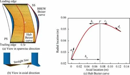
Fig.3 Geometry of IOEW.
The constraint condition for the two geometric parts in this technique is the constant axial passage area.As illustrated in the schematic diagram along the axial direction in Fig.4,the maximum BBEW height on the suction side (Ws) is used to determine PointA.And PointBis computed using the BBEW maximum height (Ws) and the blended angle (θ).Similarly,PointsCandDon the pressure suction are determined byWpand θ.The constraint of the constant axial passage area as the prototype gives the relationship for the coordinate points in Fig.4 as:

Fig.4 Schematic of full-BBEW geometry section.

This completes the full-BBEW geometry construction with an overall view as shown in Fig.5.However,the large geometric design space and optimization method limits the design parameters,which are simplified as follows:
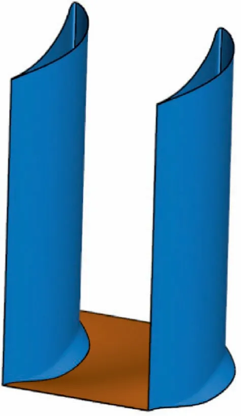
Fig.5 Final geometry of full-BBEW.
(1) The blended angle θ is set to 45°.That is,the maximum thickness in the blended profile at the hub is equal to the maximum blended height,Ws.
(2) The IOEW causes the dihedral angle between the pressure side and the endwall to be greater than 90°.In addition,the separation on the pressure side is not as large because of the relatively high pressure.Therefore,only the suction side has BBEW structure while the BBEW maximum height on the pressure side is zero.
(3) To avoid abnormal profiles for the Bezier curves and to reduce the number of control parameters,the length parameters of the Bezier curves are simplified as follows usingrs1.And control parameter of the IOEW curves is defined in a similar way:

Finally,the geometric construction and parameterization method shown above is used to develop the six key geometric design variables for further study,including the maximum BBEW height (Ws),position of the maximum BBEW height(Wsx),maximum hub inclined angle (β),position of the maximum inclined angle (btx),BBEW Bezier polynomial control parameter (rs1),and IOEW Bezier curve control parameter(rs2).
To explore the best design geometry for the full-BBEW technique and the flow mechanism,the geometric characteristics are used to determine three different models.The optimized case of each model is used as a comparison to find the design experiments for the full-BBEW technique as:
(1) BBEW model:Special treatment of the zero inclininghub angle (β).This BBEW model maintains the same axial area,which is different from the traditional BBEW technique.
(2) IOEW model:The BBEW maximum height is set to zero to explore the effect of the inclining hub.
(3) Full-BBEW model:This general model has six design parameters.This research explores these three models,which are the different geometries of the full-BBEW technique with specific parameters.In order to distinguish these names,we used the collective terms ‘‘full-BBEW technique”to refer to this technique.And the terms ‘‘full-BBEW model”,‘‘IOEW model”and‘‘BBEW model”are used to refer to the classifications.
2.2.Numerical setup
The numerical method is introduced as follows after the geometry construction of the full-BBEW technique.To ensure the boundary layer can develop naturally to a specific state,the axial distance from the inlet to the leading edge is set to 1000 mm and the axial length of the downstream fluid domain is 300 mm.The computational domain is shown in Fig.6 where the inlet is greatly extended for boundary layer development.The multi-block structured grid is automatically constructed using the AUTOGRID software by importing the section lines for the pressure and suction surface and nonaxisymmetric endwall profile.
The numerical simulations are conducted using the Ansys CFX.The full Reynolds Averaged Navier-Stokes (RANS)equation is used with the Shear Stress Transport (SST) turbulent model,25which shows a relatively good prediction for corner separation.The conditions of previous experiments define the boundary conditions at the inlet total pressure as 104,536 Pa and the inlet total temperature as 322 K as well as dictating the inlet flow direction and outlet averaged static pressure.To maintain the same boundary layer thickness condition before leading edge,the inlet velocity is controlled to exactly Mach number 0.6 by carefully adjusting the outlet static pressure.As shown in Fig.6,the hub and blade are defined as non-slip and adiabatic.Besides,the shroud is prescribed with the symmetry boundary condition to avoid interactions of the up and down corner separations.The experimental data at Mach number 0.2 validates the gird independence.The four cases with different grid numbers and different minimization sizes for the grid cells adjacent to the wall surface(D)are given in Table 2.
The spanwise distributions of the total pressure loss coefficient(ω)for the validation cases are given in Fig.7(a).Nearly all the cases show good predictions in the mainstream region while the latter two cases exhibit fewer errors over the entire span range.Considering the computational efficiency and accuracy in the corner region,the Case 3 grid set with 2 million nodes and a 0.001 mm minimum wall distance is used for the simulations,whosey+of the solid surfaces is less than 1,as shown in Fig.7(b).
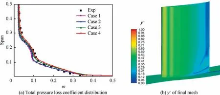
Fig.7 Grid independency verification.
3.Geometric models optimization
The large design space of the three implemented models signifies a relatively low calculation efficiency when using conventional global optimization methods.To acquire the best design cases for the full-BBEW technique with an acceptable cost,the response surface method based on the Kriging surrogate model are used,26where the six design parameters are sampled with the Latin hypercube method,as shown in Table 3.The detailed optimization process for the full-BBEW is introduced next.The key to the response surface method is the adequate and well-distributed sample points to fit the response function.The research sampled 80 points for the full-BBEW model.

Table 2 Validation cases.

Table 3 Sampling range of design parameters.
The flow fields of the sampling points are then simulated using the numerical method described above.The performance assessment of the sample points (objective function) is chosen as the mass-averaged total pressure loss coefficient in the cascade at the axial section 80 mm from the trailing edge,which is computed using Eq.(4) as

whereP01is the inlet total pressure,P1is the inlet static pressure,andP0is the total pressure on the computing plane,which are all mass-averaged.
The design parameters of the sampling points and corresponding total pressure loss are used to construct the response surface.The Kriging surrogate model is used,and its regression agent model applies a second-order polynomial,where the correlation model utilizes a cubic spline curve.After the response surface is obtained from the initial points,the genetic algorithm in the MATLAB optimization toolbox is used to perform the global search and find the optimal point of the current response surface.The numerical simulations of the optimized design point are then performed as verification.After the simulations,the parameters of this point and the corresponding loss are supplemented into the response surface to further reduce the prediction errors.This process is repeated until the optimal solution of each case is obtained.Thirteen additional points are added during the optimization process for the full-BBEW model until the minimum loss result is found.The entire process is shown in Fig.8.
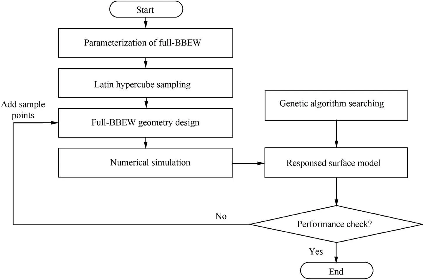
Fig.8 Optimization process.
The designs with minimized losses of the BBEW,IOEW,and full-BBEW models are shown.Different numbers of sampling points are used in the optimization process for these models.The BBEW uses 30 initial sampling points and 23 supplemented points.The IOEW uses 20 initial points and adds another 5 for the optimization process.However,the double design variables cause the sampling quantity for the full-BBEW model to be much more than the above two where total of 93 (80+13) cases are used in the optimization process.
4.Numerical results and analysis
4.1.Overall performance
The optimal results of the three models are shown in Fig.9.The optimized parameters for each model at the design point are shown in Table 4.Previous works indicate that the more influential design parameters are theWs,β,and their corresponding locations.18The best blade contouring height (Ws)is around 8 mm in the inlet boundary condition and between 20%–40% of the axial chord.On the other hand,the maximum inclining angle is located at 63% of the axial chord in both the IOEW and full-BBEW models.The overall performances of the models at 160%of the axial chord are also given in Table 4.Under the same inlet velocity,three models of this technique can decrease the high losses while maintaining the same averaged mass flow(˙m).The loss reduction of the BBEW and full-BBEW models reach 8.66% while the IOEW model reaches 7.84%,where the total pressure loss does not differ much between models.However,the full-BBEW model is more useful at reducing the aerodynamic blockage coefficientB(defined in Eq.(5)) compared with the other two models.

Fig.9 Optimal geometries of three models.

where the subscript ‘‘e”represents the variables in the main flow region out of the boundary layer,which are mass flowaveraged;ρ represents the density whileVis the velocity at the same location andAis the area of boundary layer at every axial location.
After considering the geometric parameters and overall performance of the design conditions,the total pressure coefficient over the entire operational conditions of the full-BBEW technique is shown in Fig.10.Three models significantly decrease the loss between incidences of-12°and 8°,especially for large negative incidences where the separation focus is in the corner.But because the current optimization is a singlepoint global optimization and there is no mandatory constraint at the non-design conditions,the improvement is not significant for large incidences above 8°.Meanwhile,three models of the full-BBEW technique do not differ significantly in terms of the total pressure loss.In the following,the details of the-5°and 6°incidences are used to analyze the non-design condition flows and evaluate the effects of the full-BBEW over all operational conditions.
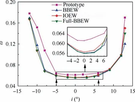
Fig.10 Total pressure loss coefficient at different incidence angles.
4.2.Loss and blockage
To determine the mechanism for performance improvements and the impact of the full-BBEW technique on the cascade,this section presents extensive and detailed flow analyses for the different models at various incidences.First,the span distribution of total pressure loss at the axial position of 160%chord location is presented in Fig.11.The comparison shows that the loss is redistributed over the entire spanwise section.At the design point,the losses for the three modes decrease below 25% span where the corner separation is stored.The loss slightly increases between 25%–40% span while it keeps the same in the mainstream.However,under the circumstances of the unchanged passage area and almost the same mass flow,full-BBEW technique can improve the separation in corner and keep positive effect on the whole.The differences in losses between the three models are not significant.The full-BBEW decreases the most in the corner but increased the most near the main flow,which was followed by the IOEW due to the different flow migrations.Overall,the loss effectively decreases based on the results of Table 4.

Fig.11 Spanwise distribution of total pressure loss coefficient at 160% axial chord location in 0° incidence.

Table 4 Geometry parameters for the optimal cases.
The loss distribution at non-design conditions is presented in Fig.12.The three models decrease the loss in the corner separation under both conditions.The loss distribution at 6°incidence maintains the same form as the design condition,but the loss at the mainstream increases more than that under the design condition due to the motion of the endwall cross-flow and vortex separation at higher span.Therefore,the total pressure loss decreases slightly with a slight improvement in the performance for large incidences and the losses for the three models maintain similar values over the entire operational range.In contrast,a large separation of the prototype accumulates in the corner below the 30% span at -5°incidence whilethe three models reduce this separation and exhibit little influence on the mainstream flow.The trend of the three models for negative incidences is similar to the design condition,but the full-BBEW model has a slightly better performance than the other two for the corner separation reduction.
To further explore the reasons for the significant loss in the redistribution from the endwall towards the midspan over different operating conditions,the contours of the total pressure loss coefficient at the 160% axial chord location for the three models and the vortex structure at the design condition are illustrated in Fig.13.The size and location of the separation vortex change due to the different geometries.At the design point,the total pressure loss is nearly the same as the prototype in the mainstream (over 40% span) while the three full-BBEW models have significantly decreased separations in the corner region.Below 10% span range,while the thickness of the separations all decrease for the three models,the BBEW and full-BBEW models have larger decreases than the IOEW model along the circumferential direction,and the corner vortex in the BBEW model is significantly weakened near the endwall.The separation bubble(Ⅰ)between 10%and 20%span is the main separation structure in the passage.The full-BBEW model decreases the separation size of the bubble Ⅰmore than the other two models under these conditions,which meets the changes for passage vortex A.However,the IOEW model has the smallest influence on the location of the low-energy bubbleⅠwhile the BBEW and full-BBEW models migrated to the 25%span.Changes in the location of the bubbles Ⅰlead to a corresponding loss increase in the mainstream,as shown in Fig.12.The bubbles,which are the low-energy flow caused by corner separation in the endwall region,roll up to the mainstream and give a reduced total pressure loss below the 30% span.Meanwhile,the strength of the counter vortex B is more significant than the prototype,especially for the BBEW model,which may be caused by secondary flow migration.
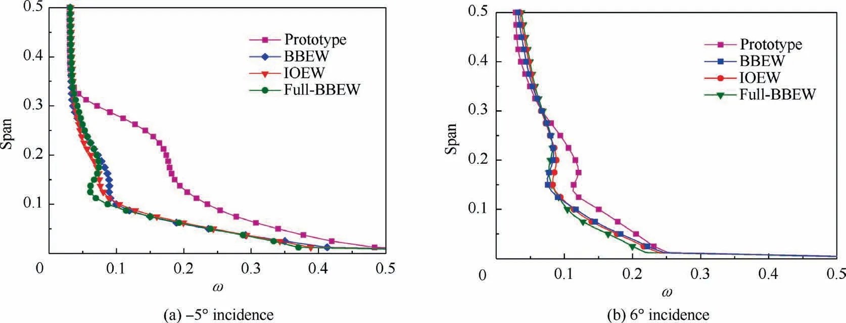
Fig.12 Spanwise distribution of total pressure loss coefficient at 160% axial chord location at non-design conditions.

Fig.13 Contours of total pressure loss coefficient at 160% axial chord location.
The flow structure for off-design conditions is similar to the design point results.However,the negative incidence condition leads to a smaller resulting suction side vortex so that the loss of the prototype in the mainstream is less than for positive incidences.The separation that accumulates below the 25% span is caused primarily by the boundary layer intersection.Under this condition,the three models decrease the total pressure loss over nearly the entire span range while the loss of the mainstream is the same.The maximum values of the total pressure loss in the bubble Ⅰreduce from 1.0 to 0.7,and the full-BBEW decreases the most by further moving up the low-energy flow.Therefore,the full-BBEW technique can significantly improve the performance in the corner under negative incidence conditions.
At 6°incidence angle,because of the increased circumferential pressure gradient in endwall,the cross-flow subsequently rolls up to form secondary flow in the corner,resulting the increase of the total pressure loss region.In the prototype,the core of the wake thickens(or the loss core simply migrates slightly farther outboard).In this context,the size and location of the low-energy fluid vortex for the three models of full-BBEW models also changed compared with the prototype,where the high-loss area decreases significantly.Meanwhile,the cross-passage migration (pressure to suction side) is encouraged by the non-axisymmetric end wall profiling to migrate off the end wall and climb onto the suction surface of the airfoil.This causes the low-energy flow to move up over the 40%span where the full-BBEW model moves most and the BBEW model moves smallest.
As is known,corner separations are caused by interactions of the endwall cross-flow and the boundary layer on the blade,which results in an accumulation of the low momentum fluid in the corner and a high-pressure gradient in the cascade.Three models for the full-BBEW technique affect the separation for all operational conditions.It effectively decreases the loss and improves the performance when the intersection of the boundary layer plays an important role in corner separation.Under negative incidences,especially less than-5°,it weakens the large separation in the corner and greatly reduced the loss over a large span range.On the other hand,the spanwise distribution of the loss for the 6° incidence is similar as it under the design condition.However,the relatively higher loss in the mainstream causes the performance to be relatively the same as the prototype.
In addition to the total pressure loss,another important evaluation parameter for the performance is the aerodynamic blockage coefficientB(defined in Eq.(5)),which shows the throughflow capability.Further studies represent the aerodynamic blockage in the axial direction along the blade at -5°,0°,and 6° incidences,as shown in Fig.14.TheBeffectively decreases over the entire chordwise and it is an important benefit of full-BBEW model.As the BBEW geometry is located primarily at the former region of the blade(shown in Table 4),the blockage on the BBEW and full-BBEW models start to decrease almost from the leading edge.The blockage on the IOEW model has a large reduction near the region of the maximum inclining angle.At the end of the blade,the aerodynamic blockage on the BBEW model has a minimum decrease,but the full-BBEW model has the greatest improvement on the throughflow capability.Moreover,the blockage for offdesign conditions decreases,and the difference between the three models follows the same trend as the design point.The differences in the losses between the three models are not significant,but the full-BBEW model has the largest reduction in the aerodynamic blockage coefficient.However,the aerodynamic blockage at negative incidence angles also has a better performance than for positive angles.At 6° incidence,the full-BBEW technique improves the performance after the middle of the blade and maintains a similar increased speed as the prototype.In contrast,the blockage decreases over the entire blade chordwise for the -5° incidence,which means the full-BBEW geometry has a better anti-blockage ability in the corner for weaker secondary flows.

Fig.14 Axial distributions of aerodynamic blockage coefficient along blade for different incidences.
The two main parameters that affect the corner separation are the intersection of the boundary layer and the secondary cross-flow near the end wall.Previous research has shown that the BBEW geometry mostly decreases the intersection of the boundary layer while the inclining hub of the IOEW is performed for high secondary flow situations.Under normal circumstances,the intersection of the boundary layer plays an important role in negative incidences.Thus,to better understand the flow mechanism of the BBEW,the results of the BBEW and full-BBEW models for -5° incidence are used for analyses and comparisons.At the same time,the large incidence may lead to more significant secondary flows.In this case,the flow phenomenon of the IOEW and full-BBEW models at 6°incidence are presented to evaluate the influence of the inclining hub on the secondary flow.
4.3.Flow details of prototype,BBEW,and full-BBEW at -5°incidence
Previous works have designed the BBEW based on the dihedral theory.To show the effects of the dihedral angle of the corner on the intersected boundary layer,Fig.15 illustrates the contours of the axial velocity at the 64%axial chord position at-5°incidence.Considering that it is too difficult to precisely determine the edge of the corner separation,the difference in the flow accumulation is used to indicate the degree of separation.The separation in the corner with an obtuse dihedral angle geometry is weakened relative to a right angle.The BBEW and full-BBEW models nearly eliminate the negative velocity at this chord location.The full-BBEW model has a larger reduction at the intersection of the boundary layer on the blade by moving up the low-velocity flow.

Fig.15 Contours of axial velocity at 64% axial chord location at -5° incidence.
To further evaluate the boundary layer in the corner,the shape factor along the chordwise direction is presented in Fig.16 to show the effect of the boundary layer.Previous work has shown that a shape factor is not existed when it is larger than 2.2,which indicates the boundary layer has separated.Therefore,the prototype has a large separation after the 60% chord while the BBEW reaches to the limit after the 80%chord.However,the full-BBEW reduces the shape factor along the entire blade and suppresses the intersection of the boundary layer.On the other hand,the value of the shape factor suggests the influence of the boundary layer flow on the mainstream.Before the 40% chord,the flow in the boundary layer of the BBEW and full-BBEW models have larger impacts on the mainstream than the prototype.This may be because the BBEW geometry moves up the low-energy flow from the boundary layer to the mainstream which corresponds to the changes in the loss in Fig.13.

Fig.16 Boundary layer shape factor along blade.
To determine the flow mechanism at the endwall region due to the obtuse dihedral angle of the BBEW geometry,Fig.17 presents the limiting streamlines on the suction surface and hub and the contour of the pressure gradient in the radial direction.Compared with the prototype,the full-BBEW models change the structure,size,and location of the corner separation.The streamlines in the prototype indicate the flow rolls up from the former part of the blade along the radial direction,which results in large separation bubbles near the trailing edge region.The streamlines of full-BBEW models become smooth along the wall surfaces before the middle of the blade and separation because the intersection of the boundary layers is not as strong as that in the prototype.As a result,the lowenergy flow does not remain in the corner region and transports downstream,which leads to a decreased blockage and lower loss.The red point on the suction surface are drawn in Fig.17 to show the starting point of the reverse flow.The start of the reverse flow on the suction surface of the BBEW and full-BBEW models are delayed,which prevents the loss accumulation and local separation near the endwalls.As shown by the pressure gradient in the square box,the flow migration is because the BBEW geometry creates a radial pressure gradient at the edge of the contour that acts towards the mid-span at the maximum height of the BBEW.The increased radial pressure gradient leads to a spanwise migration of the fluid and the increased shape factor before the 40%chord position.This suggests an upward movement of the low-energy fluid far from the corner,as shown by the analysis of loss distribution and higher passage vortex in the limiting streamlines.
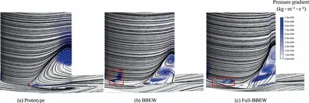
Fig.17 Contours of radial pressure gradient on suction side and limiting streamlines.
4.4.Flow details of prototype,IOEW,and full-BBEW at 6°incidence
This study introduces the flow mechanism of the BBEW geometry based on the -5° incidence.The radial pressure gradient causes the low-energy flow to migrate and reduces the boundary layer intersection.However,there are relatively stronger secondary flows at larger incidences.Thus,the flow details of the prototype,IOEW,and full-BBEW at a 6° incidence are presented and analyzed to determine the effects of the IOEW geometry on the flow,especially the secondary flow,at the hub.
The contours of the static pressure at the mid-span and near the hub are illustrated in Fig.18.The distributions of the static pressure for the three models are nearly the same as the prototype at the mid-span.The geometry of the full-BBEW models in the corner has little impact on the flow above the 50%span.However,the pressure distribution on the hub is different.The angle between the axial direction and isolines of the static pressure inside the passage decrease in the latter part of the blade for the IOEW and full-BBEW models.Compared with the prototype,the pressure component in the circumferential direction decreases,which results in flow transport downstream and avoids flow storage along the streamwise direction near the hub.However,the contours of the static pressure show that the inclining hub has little influence on the cross-flow near the hub.Thus,the effects of the IOEW on the secondary flow needs further exploration.
The spanwise static pressure did not exhibit flow transport in the corner.Thus,the distribution of the static pressure and the velocity vectors at the 78%chord location are presented in Fig.19.The velocity vectors near the hub along the circumferential direction of the IOEW and full-BBEW models are nearly the same as the prototype,which corresponds to the results in Fig.18.It is shown that the inclining hub geometry cannot effectively decrease the cross-flow.However,the vectors distribution of the IOEW and full-BBEW models change along the radial direction near the suction side.As shown by the arrows,the flow migrates from the hub and climbs onto the blade.The upward flow transport causes an increased climbing flow on the blade with a nearly unchanged cross-flow.Meanwhile,the static pressure contours help to explain the flow mechanism.Though the static pressure along the circumferential direction for the different models maintains the same distribution,the static pressures of the IOEW and full-BBEW models increase along the spanwise direction of the corner region.As shown by the red box,the IOEW and full-BBEW geometries create a radial pressure gradient near the blade that acts towards the mid-span.The increased static pressure in this region moves up the stored flow in the corner to the mainstream and results in a low-energy flow that climbs onto the blade,especially for the full-BBEW model.Therefore,though the radial pressure gradient causes a decreased loss in the corner for the spanwise distribution at large incidences,the loss of the mainstream increases significantly so that the total loss is not reduced.

Fig.19 Distribution of static pressure and velocity vector at 78% chord location.
To further show the flow details at 6° incidence,the contours of the total pressure along the blade and the streamlines in the corner is shown in Fig.20.In the prototype,the reverse flow starts from the blade before the trailing edge and spreads out to the upstream separation point at the corner.The crossflow from the hub(shown as red streamlines)brings the reverse flow to the suction surface and further transport towards the trailing edge well onto the blade,which mixes with the boundary layer intersection and leads to significant corner separation and total pressure decrease.However,the inclining hub profile encourages the secondary cross-flow to migrate off the endwall and onto the suction surface of the airfoil.Compared with the prototype,the low-energy flow accelerates and pushes up into the mainstream due to the radial pressure gradient.In the full-BBEW model,both the inclining hub and the BBEW geometry lift the streamlines from the hub and blade and push the flow downstream.Therefore,the geometry not only effectively reduces the area of the reverse flow closest to the corner but also extends it radially outward so that it reaches the midheight.

Fig.20 Contour of total pressure on hub and streamlines in corner at 6° incidence.
The results of the outlet flow angle(α)are shown in Fig.21.The reduced corner separation weakens the overturning of the flow angle and further enhances the throughflow capability,especially for the full-BBEW model.Meanwhile,the lifted low-energy flow rolls up into the passage vortex at the mainstream and results in an increased outlet flow angle.In other words,the blade contour geometry redistributes the outlet flow angle in the spanwise direction and results in a change to the blade loading.

Fig.21 Outlet flow angle.
In conclusion,to explore the flow mechanism of different geometry in full-BBEW technique,BBEW model,IOEW model and full-BBEW model are constructed and compared.The full-BBEW technique constructs a blended blade region in the corner using an enlarged dihedral angle and creates a radial pressure gradient that moves the low-energy flow up to the mainstream,which weakens the separation caused by the boundary layer intersection.Moreover,this technique pushes the flow up to the blade by the radial pressure gradient and avoids flow accumulation in the corner.As a result,the loss for the 25%–40% span increases slightly because of the upward movement of the low-energy flow,but the overall loss is reduced based on a reasonable design of the full-BBEW geometry.
5.Conclusions
Full-BBEW technique is proposed that further reduces losses and enhances the diffusion capability in the endwall region of blade rows in compressors.The main conclusions are as follows:
(1) Under Mach number 0.6 inlet conditions,three models for the full-BBEW technique decrease the total pressure loss and separation in the corner region.At the design point,the reduced loss coefficient from the BBEW and full-BBEW models reach 8.66% while the IOEW model reaches 7.84%.
(2) The three models for the full-BBEW technique decrease the aerodynamic blockage coefficient significantly and improve the diffusion capability.Though the total pressure loss does not differ significantly between the three models,the aerodynamic blockage of the full-BBEW model has a better performance than the other two over the entire operational range which is an important benefit of full-BBEW model.
(3) The full-BBEW technique changes the structure,size,and location of the corner separation.The BBEW geometry enlarges the dihedral angle and creates a radial pressure gradient to move the low-energy flow up into the mainstream.Inclining hub geometry also migrates the corner flow from the endwall to the suction surface from the increased radial static pressure gradient in the corner,while the cross-flow does not significantly decrease.As a result,the full-BBEW effectively reduces the corner separation at the endwall region but the mainstream loss increases.
(4) The full-BBEW technique can decrease the corner separation for negative incidence angles where the loss is caused primarily by the intersection of the boundary layer.For large incidences,the lifted low-energy flow climbs onto the suction surface,which not only decreases the flow storage in the corner but also increases the loss into the mainstream so that the loss is maintained at the same level as the prototype.
Declaration of Competing Interest
The authors declare that they have no known competing financial interests or personal relationships that could have appeared to influence the work reported in this paper.
Acknowledgments
This work was sponsored by the National Natural Science Foundation of China(Nos.51676015 and 51976010),National Major Science and Technology Project of China(Nos.2017-II-0006-0020 and 2017-II-0001-0013) and Beijing Institute of Technology Research Fund Program for Young Scholars,China.
杂志排行
CHINESE JOURNAL OF AERONAUTICS的其它文章
- Parameter effects on high-speed UAV ground directional stability using bifurcation analysis
- Supersonic flutter control and optimization of metamaterial plate
- Review of in-space assembly technologies
- Utilisation of turboelectric distribution propulsion in commercial aviation:A review on NASA’s TeDP concept
- The influence of inlet swirl intensity and hot-streak on aerodynamics and thermal characteristics of a high pressure turbine vane
- Evolution of wall flow structure and measurement of shear stress issuing from supersonic jet with extended shelf
